CN213860419U - Injection mold with slide delay mold opening function - Google Patents
Injection mold with slide delay mold opening function Download PDFInfo
- Publication number
- CN213860419U CN213860419U CN202021965887.5U CN202021965887U CN213860419U CN 213860419 U CN213860419 U CN 213860419U CN 202021965887 U CN202021965887 U CN 202021965887U CN 213860419 U CN213860419 U CN 213860419U
- Authority
- CN
- China
- Prior art keywords
- slide
- ejection
- limiting
- mold
- core
- Prior art date
- Legal status (The legal status is an assumption and is not a legal conclusion. Google has not performed a legal analysis and makes no representation as to the accuracy of the status listed.)
- Active
Links
Images



Landscapes
- Moulds For Moulding Plastics Or The Like (AREA)
Abstract
An injection mold for line-position delayed mold opening comprises a fixing assembly, a forming assembly, a line-position assembly and a limiting assembly, wherein the fixing assembly comprises an upper template and a lower template; the forming assembly comprises an upper die core and a lower die core, and is respectively connected with the upper template and the lower template; the slide assembly comprises an inclined guide rod, a slide block, an elastic reset piece and a slide insert, the slide block is arranged on the lower template in a sliding manner, the inclined guide rod is arranged on the upper template and used for driving the slide block to slide, the slide insert is arranged on the lower die core in a sliding manner, and the elastic reset piece is positioned between the slide insert and the lower die core; the limiting assembly comprises a limiting rod and a limiting block, a limiting hole is formed in the upper end of the slide insert, the limiting rod is fixed on the upper die core, the limiting rod penetrates through the limiting hole, and the limiting block is fixed on the lower die plate. The utility model discloses an injection mold of slide time delay die sinking can postpone when the die sinking and open the slide for the product is difficult and slide adhesion, thereby improves the product outward appearance, prevents that the product from warping.
Description
Technical Field
The utility model relates to an injection mold field especially relates to an injection mold of slide time delay die sinking.
Background
An injection mold is a molding tool provided therein for forming a plastic part, and is generally divided into a movable mold and a fixed mold, wherein when the fixed mold and the movable mold are fastened together, heated and melted plastic is injected into a mold cavity at high pressure by an injection molding machine, and is cooled and solidified to obtain the plastic part.
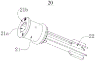
Referring to fig. 2, the electronic cigarette holder component 20 includes a head portion 21 and a tail portion 22, the head portion 21 has a hollow hole 21a, the hollow hole 21a extends from the head portion 21 to the tail portion 22, the head portion 21 further has an end surface 21b, and the end surface 21b is a plane.
For such products, the existing injection mold can use a core-pulling slider structure to form a hollow hole, but the existing mold cannot directly form a plane on the end face structure of the head of the electronic cigarette holder part. Because, in order to ensure that the product is smoothly demoulded, when the end face structure is formed, a certain demoulding angle is usually designed on the cavities of the upper mould and the lower mould, so as to ensure the smooth demoulding of the product. Some moulds can design the line position in the terminal surface structure department of the head of electron cigarette frame part to guarantee that terminal surface structure is a plane, but this kind of mode leads to product and the adhesion of line position very easily, leads to product deformation or outward appearance damage, makes the yields of product low, and production quality is poor.
SUMMERY OF THE UTILITY MODEL
The utility model aims at overcoming the weak point among the prior art, provide one kind and can delay the mould of opening the line position when the die sinking and make the product can not with the adhesion of line position to improve product appearance, prevent that the product from warping.
The purpose of the utility model is realized through the following technical scheme:
an injection mold of slide time delay die sinking, includes:
the fixing assembly comprises an upper template and a lower template, and the upper template and the lower template are arranged oppositely;
the upper die core and the lower die core are oppositely arranged, the upper die core is connected with the upper template, an upper molding groove and a glue injection hole are formed in the upper die core, the glue injection hole is communicated with the upper molding groove, the lower die core is connected with the lower template, and a lower molding groove is formed in the lower die core;
the slide assembly comprises an inclined guide rod, a slide block, a reset elastic piece and a slide insert, the slide block is arranged on the lower template in a sliding manner, the slide block is arranged at one side of the lower die core, the slide block is provided with an inclined guide hole, the inclined guide rod is arranged on the upper template and penetrates through the inclined guide hole, the inclined guide rod is used for driving the slide block to slide on the lower template, the slide insert is arranged on the lower die core in a sliding manner, the slide block is used for pushing the slide insert to move towards the direction close to the lower die core, the resetting elastic piece is positioned between the slide insert and the lower die core and used for pushing the slide insert to move in a direction away from the lower die core; and
the limiting assembly comprises a limiting rod and a limiting block, a limiting hole is formed in the upper end of the slide insert, the limiting rod is fixed on the upper die core, the limiting rod penetrates through the limiting hole, the limiting block is fixed on the lower template, and the limiting block is used for abutting against one surface, far away from the lower die core, of the slide insert;
after the upper mold core and the lower mold core are buckled, the upper molding groove and the lower molding groove are used for jointly enclosing an injection molding cavity, and the slide block and the slide insert are used for sealing the injection molding cavity.
In one embodiment, the number of the limiting rods is two, and the slide insert is provided with two limiting holes.
In one embodiment, a chamfer structure is arranged at one end, close to the slide insert, of the limiting rod, and a chamfer structure is arranged at one end, close to the limiting rod, of the limiting hole.
In one embodiment, an elastic piece accommodating groove is formed in one surface, close to the lower die core, of the slide insert, and the elastic piece accommodating groove is used for accommodating the reset elastic piece.
In one embodiment, the slide assembly further comprises a core-pulling block, the core-pulling block is fixedly arranged on one surface of the slide block close to the lower mold core, and the core-pulling block is used for extending into the injection molding cavity when the upper mold core and the lower mold core are closed.
In one embodiment, the injection mold for line-position time-delay mold opening further includes a guide pillar, the upper mold plate has an upper guide hole, the lower mold plate has a lower guide hole, and the guide pillar is inserted into the upper guide hole and the lower guide hole.
In one embodiment, the guide post is provided with a plurality of oil grooves.
In one embodiment, the injection mold for slide time-delay mold opening further includes an ejection assembly, the ejection assembly includes an ejector pin and an ejection fixing plate, the ejection fixing plate is located on one side of the lower mold plate away from the lower mold core, the lower mold core is provided with an ejection hole, the ejection hole is communicated with the lower molding groove, the lower mold plate is provided with an ejection guide hole, the ejection guide hole is communicated with the ejection hole, the ejector pin is fixed on the ejection fixing plate, and the ejector pin is inserted into the ejection hole and the ejection guide hole.
In one embodiment, the ejection assembly further comprises an ejection elastic member, and the ejection elastic member is located between the lower die plate and the ejection fixing plate.
In one embodiment, the ejection elastic member is provided in plurality.
Compared with the prior art, the utility model discloses at least, following advantage has:
1. the utility model discloses an injection mold of slide time delay die sinking is through setting up fixed subassembly, forming assembly, slide subassembly and spacing subassembly for can be in this mould one shot forming at electron cigarette support product, and can go out the planar structure of the terminal surface on the head of electron cigarette support in the mould direct forming, can also prevent the slide structure adhesion of product itself and mould when the die sinking, thereby reduce the product deflection, prevent the outward appearance damage, make the yields of product high, and production quality is good.
2. The utility model discloses an injection mold of slide time delay die sinking compact structure, durability are good, insert to the slide through setting up spacing subassembly in the mould and control for the mould can restrict the slide and insert the delay certain time when the die sinking and open again, thereby make the planar structure of terminal surface on the head of electron cigarette support can direct forming and on-stick mould. Compared with the conventional cylinder and oil cylinder control structure, the limiting assembly is simple in structure and small in size, and can simply and efficiently realize the limiting function in the limited die space.
Drawings
In order to more clearly illustrate the technical solutions of the embodiments of the present invention, the drawings that are required to be used in the embodiments will be briefly described below, it should be understood that the following drawings only illustrate some embodiments of the present invention, and therefore should not be considered as limiting the scope, and for those skilled in the art, other related drawings can be obtained according to the drawings without inventive efforts.
Fig. 1 is a schematic structural view of an injection mold with slide delay mold opening according to an embodiment of the present invention;
FIG. 2 is a schematic structural diagram of an electronic cigarette holder component;
FIG. 3 is a schematic diagram of the row bit assembly of FIG. 1;
fig. 4 is a schematic structural diagram of the ejection assembly in fig. 1.
Detailed Description
In order to facilitate understanding of the present invention, the present invention will be described more fully hereinafter with reference to the accompanying drawings. The preferred embodiments of the present invention are shown in the drawings. The invention may, however, be embodied in many different forms and should not be construed as limited to the embodiments set forth herein. Rather, these embodiments are provided so that this disclosure will be thorough and complete.
It will be understood that when an element is referred to as being "secured to" another element, it can be directly on the other element or intervening elements may also be present. When an element is referred to as being "connected" to another element, it can be directly connected to the other element or intervening elements may also be present. The terms "vertical," "horizontal," "left," "right," and the like as used herein are for illustrative purposes only and do not represent the only embodiments.
Unless defined otherwise, all technical and scientific terms used herein have the same meaning as commonly understood by one of ordinary skill in the art to which this invention belongs. The terminology used herein in the description of the invention is for the purpose of describing particular embodiments only and is not intended to be limiting of the invention. As used herein, the term "and/or" includes any and all combinations of one or more of the associated listed items.
Referring to fig. 1 and fig. 3, an injection mold 10 with a slide-delayed mold opening function includes:
the fixing assembly 100, the fixing assembly 100 includes an upper template 110 and a lower template 120, the upper template 110 and the lower template 120 are arranged oppositely;
the molding assembly 200 comprises an upper mold core 210 and a lower mold core 220, the upper mold core 210 and the lower mold core 220 are arranged oppositely, the upper mold core 210 is connected with the upper template 110, an upper molding groove 211 and a glue injection hole 212 are formed in the upper mold core 210, the glue injection hole 212 is communicated with the upper molding groove 211, the lower mold core 220 is connected with the lower template 120, and a lower molding groove 221 is formed in the lower mold core 220;
the slide assembly 300 comprises an inclined guide rod 310, a slide block 320, a reset elastic part 330 and a slide insert 340, wherein the slide block 320 is slidably arranged on the lower template 120, the slide block 320 is arranged on one side of the lower mold core 220, the slide block 320 is provided with an inclined guide hole 321, the inclined guide rod 310 is arranged on the upper template 110, the inclined guide rod 310 is arranged in the inclined guide hole 321 in a penetrating manner, the inclined guide rod 310 is used for driving the slide block 320 to slide on the lower template 120, the slide insert 340 is slidably arranged on the lower mold core 220, the slide insert 340 is abutted against the slide block 320, the slide block 320 is used for pushing the slide insert 340 to move towards the direction close to the lower mold core 220, the reset elastic part 330 is arranged between the slide insert 340 and the lower mold core 220, and the reset elastic part 330 is used for pushing the slide insert 340 to move towards the direction far away from the lower mold core 220; and
the limiting assembly 400, the limiting assembly 400 includes a limiting rod 410 and a limiting block 420, the upper end of the slide insert 340 is provided with a limiting hole 341, the limiting rod 410 is fixed on the upper mold core 210, the limiting rod 410 is inserted into the limiting hole 341, the limiting block 420 is fixed on the lower template 120, and the limiting block 420 is used for abutting against one surface of the slide insert 340 away from the lower mold core 220;
after the upper mold core 210 and the lower mold core 220 are fastened, the upper molding groove 211 and the lower molding groove 221 are used for enclosing an injection molding cavity together, and the slide block 320 and the slide insert 340 are used for sealing the injection molding cavity.
It should be noted that, the upper mold plate 110 and the lower mold plate 120 are disposed opposite to each other, the upper mold core 210 may be installed on one surface of the upper mold plate 110 close to the lower mold plate 120 by bolts, the lower mold core 220 may be installed on one surface of the lower mold plate 120 close to the upper mold plate 110 by bolts, the upper molding groove 211 on the upper mold core 210 is disposed on one surface of the upper mold core 210 close to the lower mold core 220, the lower molding groove 221 on the lower mold core 220 is disposed on one surface of the lower mold core 220 close to the upper mold core 210, and when the upper mold plate 110 and the lower mold plate 120 are close to each other and the upper mold core 210 and the lower mold core 220 are fastened together, the upper molding groove 211 and the lower molding groove 221 are configured to jointly enclose an injection molding cavity. In this embodiment, the upper platen 110 is connected to an injection system of an injection molding machine, and the lower platen 120 is connected to a clamping system of the injection molding machine. During injection molding, a rubber material channel can be formed in the upper mold plate 110 and communicated with the rubber injection hole 212, so that rubber material can enter the rubber material channel from an injection molding system of an injection molding machine, then enter the rubber injection hole 212, finally enter an injection molding cavity, and be cooled to form a product. It should be noted that the slide block 320 is slidably disposed on the lower mold plate 120, the slide insert 340 is slidably disposed on the lower mold core 220, and one side of the slide block 320 close to the lower mold core 220 and one side of the slide insert 340 close to the lower mold core 220 are used for closing an injection molding cavity together to form the end surface 21b of the electronic cigarette support 20. One end of the slide block 320 close to the lower mold core 220 may be provided with a protrusion, which extends into the injection cavity to form the hollow hole 21a of the electronic cigarette holder 20 during mold closing. In this embodiment, the slide block 320 is driven by the inclined guide rod 310 to move, the inclined guide rod 310 is disposed on the upper mold plate 110, the inclined guide rod 310 is disposed to be inclined at a certain angle with respect to the upper mold plate 110, the inclined guide rod 310 is inclined outward, i.e., inclined in a direction away from the mold center, the inclined guide hole 321 of the slide block 320 is also inclined at a certain angle with respect to the lower mold plate 120, and the inclined guide hole 321 is adapted to the inclined angle of the inclined guide rod 310. Thus, when the upper and lower molds are closed or separated, the inclined guide rods 310 are inserted into the inclined guide holes 321, and the inclined guide rods 310 slide in the inclined guide holes 321, so that the slide blocks 320 move on the lower mold plate 120 to move closer to or away from the lower mold core 220. The line insert 340 is slidably disposed on the lower mold core 220, and the line insert 340 abuts against the line slide block 320, in a mold closing state, the elastic restoring member 330 between the line insert 340 and the lower mold core 220 is in a compressed state, the elastic restoring member 330 may be a spring, the limiting rod 410 fixed to the upper mold core 210 is inserted into the limiting hole 341 to limit the line insert 340 from moving in a direction away from the lower mold core 220 under the pushing of the elastic restoring member 330, when the mold is gradually opened, the limiting rod 410 disposed on the upper mold core 210 is gradually pulled out from the limiting hole 341, when the limiting rod 410 is completely pulled out from the limiting hole 341, the elastic restoring member 330 between the line insert 340 and the lower mold core 220 extends and pushes the line insert 340 to move in a direction away from the lower mold core 220, the line insert 340 moves in a direction away from the lower mold core 220 until the line insert 340 abuts against the limiting block 420, the row insert 340 stops moving. Through the above arrangement, the slide insert 340 can be delayed for a period of time after the mold is opened, and then moves in a direction away from the lower mold core 220 under the pushing of the elastic restoring member 330.
To sum up, the utility model discloses an injection mold 10 of slide time delay die sinking's the process of moulding plastics as follows:
in an initial state, the mold is in an open state, the upper mold plate 110 can be connected with an injection molding system of an injection molding machine, the lower mold plate 120 can be connected with a mold closing system of the injection molding machine, the lower mold plate 120 is pushed by the mold closing system to approach the upper mold plate 110, at this time, the slide block 320 slidably disposed on the lower mold plate 120 is located at an extreme position far away from the lower mold core 220, the inclined guide rod 310 fixed on the upper mold plate 110 is in contact with the inclined guide hole 321 slidably disposed on the slide block 320 on the lower mold plate 120, during the gradual mold closing process, the inclined guide rod 310 is gradually inserted into the inclined guide hole 321, the slide block 320 is gradually moved towards a direction close to the lower mold core 220 under the driving of the inclined guide rod 310, during the movement process, the slide block 320 abuts against the slide block 340 and drives the slide block 340 to move together towards a direction close to the lower mold core 220, and the return elastic element 330 located between the slide block 340 and the lower mold core 220 is compressed, the limiting rod 410 arranged on the upper die core 210 is gradually inserted into the limiting hole 341 of the slide insert 340, when the slide block 320 moves to the limit position closest to the lower die core 220, the slide insert 340 is also abutted against the lower die core 220, and at this time, one end of the slide block 320 close to the lower die core 220 is abutted against one end of the slide insert 340 close to the lower die core 220. When the upper mold core 210 abuts against the lower mold core 220, the whole mold closing process is finished, then, an injection molding system of the injection molding machine is started, glue solution flows into an injection molding cavity through the glue injection hole 212, after the injection molding of a product is finished, the mold closing system drives the lower mold plate 120 to be separated from the upper mold plate 110, at the initial stage of mold separation, the inclined guide rod 310 drives the slide block 320 to move in the direction away from the lower mold core 220, the limiting rod 410 arranged on the upper mold core 210 is partially inserted into the limiting hole 341 of the slide insert 340, therefore, before the limiting rod 410 is not completely extracted from the limiting hole 341 of the slide insert 340, the slide insert 340 is still positioned at the limit position closest to the lower mold core 220, after the limiting rod 410 is completely extracted from the limiting hole 341 of the slide insert 340, the elastic reset piece 330 in a compressed state between the slide insert 340 and the lower mold core 220 pushes the slide insert 340 to move in the direction away from the lower mold core 220, until the slide insert 340 abuts against the stop block 420 fixed on the lower template 120.
Referring to fig. 1, in one embodiment, two limiting rods 410 are provided, and two limiting holes 341 are formed on the slide insert 340. It can be understood that two limiting rods 410 are arranged on the lower mold core 220, and two limiting holes 341 are correspondingly arranged on the slide insert 340, so that the stress of the slide insert 340 is balanced and cannot be inclined, and thus the smooth mold closing and opening actions of the mold are ensured.
In one embodiment, a chamfer structure is arranged at one end of the limiting rod 410 close to the slide insert 340, and a chamfer structure is arranged at one end of the limiting hole 341 close to the limiting rod 410. It can be understood that, in each mold closing process, the limiting rod 410 needs to be inserted into the limiting hole 341, one end of the limiting rod 410 close to the slide insert 340 is set to be a chamfering structure, and one end of the limiting hole 341 close to the limiting rod 410 is set to be the chamfering structure, so that the success rate of inserting the limiting rod 410 into the limiting hole 341 can be improved, and the smoothness of the mold closing process is ensured.
Referring to fig. 3, in one embodiment, an elastic member receiving groove 342 is formed on a surface of the slide insert 340 close to the lower mold core 220, and the elastic member receiving groove 342 is used for receiving the elastic member 330. It can be understood that an elastic member receiving groove 342 is formed on a surface of the row insert 340 adjacent to the lower mold core 220, so that the elastic restoring member 330 is received in the elastic member receiving groove 342 to prevent the elastic restoring member 330 from being pulled out from between the lower mold core 220 and the row insert 340.
Referring to fig. 3, in one embodiment, the slide assembly 300 further includes a core-pulling block 350, the core-pulling block 350 is fixedly disposed on a surface of the slide block 320 close to the lower mold core 220, and when the upper mold core 210 and the lower mold core 220 are closed, the core-pulling block 350 is used to extend into the injection cavity. It should be noted that, in the present embodiment, the protrusion on the slide block 320 is eliminated, and the core-pulling block 350 is installed on the slide block 320, and the core-pulling block 350 replaces the protrusion to form the hollow hole 21a of the electronic cigarette holder 20, so that the core-pulling block 350 can be replaced separately when the core-pulling block 350 is damaged, thereby saving the maintenance cost and improving the production quality of the product.
Referring to fig. 1, in one embodiment, the injection mold 10 for line-position time-delay mold opening further includes a guide pillar 500, wherein the upper mold plate 110 has an upper guide hole, the lower mold plate 120 has a lower guide hole, and the guide pillar 500 is disposed through the upper guide hole and the lower guide hole.
In one embodiment, the guide pillar 500 has a plurality of oil grooves 510.
It should be noted that, the upper mold plate 110 and the lower mold plate 120 need to make continuous relative movement in the working process, in order to improve the accuracy of the relative movement between the upper mold plate 110 and the lower mold plate 120, an upper guide hole may be formed in the upper mold plate 110, such that an axis of a hole of the upper guide hole is perpendicular to the upper mold plate 110, a lower guide hole may be formed in the lower mold plate 120, such that an axis of a hole of the lower guide hole is perpendicular to the lower mold plate 120, and the guide pillar 500 is inserted into the upper guide hole and the lower guide hole, the guide pillar 500 is in clearance fit with the upper guide hole, and the guide pillar 500 is also in clearance fit with the lower guide hole, such that the mold clamping accuracy of the upper mold plate 110 and the lower mold plate 120 is higher in the mold clamping process. In this embodiment, a plurality of oil grooves 510 are further formed in the guide pillar 500, in the actual use process, lubricating oil is often smeared on the guide pillar 500, and the plurality of oil grooves 510 formed in the guide pillar 500 can enable the lubricating oil to be stored in the oil grooves 510, so that the lubricating oil can be stored on the guide pillar 500 for a long time, and the use effect of the lubricating oil is improved.
Referring to fig. 4, in one embodiment, the injection mold 10 for line-position delayed mold opening further includes an ejection assembly 600, the ejection assembly 600 includes a thimble 610 and an ejection fixing plate 620, the ejection fixing plate 620 is located on a side of the lower mold plate 120 away from the lower mold core 220, the lower mold core 220 is provided with an ejection hole 222, the ejection hole 222 is communicated with the lower molding groove 221, the lower mold plate 120 is provided with an ejection guide hole, the ejection guide hole is communicated with the ejection hole 222, the thimble 610 is fixed on the ejection fixing plate 620, and the thimble 610 penetrates through the ejection hole 222 and the ejection guide hole. It can be understood that one end of the thimble 610 is fixed on the ejection fixing plate 620, and the other end of the thimble 610 sequentially passes through the ejection guide hole on the lower mold plate 120 and the ejection hole 222 on the lower mold core 220 to enter the lower casing groove, during injection molding, one end of the thimble 610 far away from the ejection fixing plate 620 does not extend into the lower casing groove, when injection molding is completed and the mold is opened, the ejection fixing plate 620 moves towards the direction close to the lower mold plate 120, and the thimble 610 extends into the lower casing groove and ejects a product in the lower casing groove out of the lower casing groove.
Referring to fig. 4, in one embodiment, the ejection assembly 600 further includes an ejection elastic member 630, and the ejection elastic member 630 is located between the lower mold plate 120 and the ejection fixing plate 620.
In one embodiment, the ejection elastic member 630 is provided in plurality. It is understood that the elastic ejection element 630 may be a spring, the elastic ejection element 630 is compressed when the fixed ejection plate 620 moves toward the lower mold plate 120, after the ejector pins 610 eject the product, the mold clamping system releases the fixed ejection plate 620, the elastic ejection element 630 extends and pushes the fixed ejection plate 620 to move away from the lower mold plate 120, so that the ejector pins 610 exit from the lower groove, and the elastic ejection elements 630 disposed between the fixed ejection plate 620 and the lower mold plate 120 may make the fixed ejection plate 620 more uniformly stressed, thereby preventing the fixed ejection plate 620 from being tilted relative to the lower mold plate 120.
Compared with the prior art, the utility model discloses at least, following advantage has:
1. the utility model discloses an injection mold 10 of slide time delay die sinking is through setting up fixed subassembly 100, forming assembly 200, slide subassembly 300 and spacing subassembly 400 for can be in this mould one shot forming at electron cigarette support product, and can go out the planar structure of the terminal surface on the head of electron cigarette support in the mould direct forming, can also prevent the slide structure adhesion of product itself and mould when the die sinking, thereby reduce the product deflection, prevent the appearance damage, make the yields of product high, and good production quality.
2. The utility model discloses an injection mold 10 of slide time delay die sinking compact structure, durability are good, insert 340 through setting up spacing subassembly 400 in the mould to the slide for the mould can restrict the slide and insert 340 delay certain time and open again when the die sinking, thereby make the planar structure of terminal surface on the head of electron cigarette support can direct forming and on-stick mould. Compared with the conventional cylinder and oil cylinder control structure, the limiting assembly 400 is simple in structure and small in size, and can simply and efficiently realize the limiting function in the limited die space.
The above-mentioned embodiments only represent some embodiments of the present invention, and the description thereof is specific and detailed, but not to be construed as limiting the scope of the present invention. It should be noted that, for those skilled in the art, without departing from the spirit of the present invention, several variations and modifications can be made, which are within the scope of the present invention. Therefore, the protection scope of the present invention should be subject to the appended claims.
Claims (10)
1. The utility model provides an injection mold of slide time delay die sinking which characterized in that includes:
the fixing assembly comprises an upper template and a lower template, and the upper template and the lower template are arranged oppositely;
the upper die core and the lower die core are oppositely arranged, the upper die core is connected with the upper template, an upper molding groove and a glue injection hole are formed in the upper die core, the glue injection hole is communicated with the upper molding groove, the lower die core is connected with the lower template, and a lower molding groove is formed in the lower die core;
the slide assembly comprises an inclined guide rod, a slide block, a reset elastic piece and a slide insert, the slide block is arranged on the lower template in a sliding manner, the slide block is arranged at one side of the lower die core, the slide block is provided with an inclined guide hole, the inclined guide rod is arranged on the upper template and penetrates through the inclined guide hole, the inclined guide rod is used for driving the slide block to slide on the lower template, the slide insert is arranged on the lower die core in a sliding manner, the slide block is used for pushing the slide insert to move towards the direction close to the lower die core, the resetting elastic piece is positioned between the slide insert and the lower die core and used for pushing the slide insert to move in a direction away from the lower die core; and
the limiting assembly comprises a limiting rod and a limiting block, a limiting hole is formed in the upper end of the slide insert, the limiting rod is fixed on the upper die core, the limiting rod penetrates through the limiting hole, the limiting block is fixed on the lower template, and the limiting block is used for abutting against one surface, far away from the lower die core, of the slide insert;
after the upper mold core and the lower mold core are buckled, the upper molding groove and the lower molding groove are used for jointly enclosing an injection molding cavity, and the slide block and the slide insert are used for sealing the injection molding cavity.
2. The injection mold with the line space time-delay die sinking as claimed in claim 1, wherein there are two limiting rods, and the line space insert is provided with two limiting holes.
3. The slide time-delay open-die injection die according to claim 1, wherein a chamfer structure is arranged at one end of the limiting rod close to the slide insert, and a chamfer structure is arranged at one end of the limiting hole close to the limiting rod.
4. The injection mold of claim 1, wherein a surface of the slide insert close to the lower mold core is provided with an elastic member receiving groove for receiving the elastic member for resetting.
5. The injection mold of line position time delay die sinking of claim 1, characterized in that, the line position subassembly still includes the core pulling piece, the core pulling piece is fixed to be set up on the one side that the line position slider is close to the lower mould benevolence, when the upper mould benevolence with the lower mould benevolence compound die, the core pulling piece is used for stretching into in the injection cavity.
6. The injection mold with line position time delay open mold according to claim 1, further comprising a guide pillar, wherein the upper mold plate has an upper guide hole, the lower mold plate has a lower guide hole, and the guide pillar is inserted into the upper guide hole and the lower guide hole.
7. The injection mold with line space time-lapse mold opening according to claim 6, wherein the guide post is provided with a plurality of oil grooves.
8. The injection mold of line position time delay die sinking of claim 1, characterized in that, the injection mold of line position time delay die sinking further comprises an ejection assembly, the ejection assembly comprises an ejector pin and an ejection fixing plate, the ejection fixing plate is located on one side of the lower die plate away from the lower die core, the lower die core is provided with an ejection hole, the ejection hole is communicated with the lower forming groove, the lower die plate is provided with an ejection guide hole, the ejection guide hole is communicated with the ejection hole, the ejector pin is fixed on the ejection fixing plate, and the ejector pin is arranged in the ejection hole and the ejection guide hole in a penetrating manner.
9. The slide time-lapse mold-opening injection mold according to claim 8, wherein the ejection assembly further comprises an ejection elastic member, and the ejection elastic member is located between the lower mold plate and the ejection fixing plate.
10. The slide time-lapse mold-opening injection mold according to claim 9, wherein a plurality of the ejection elastic members are provided.
Priority Applications (1)
| Application Number | Priority Date | Filing Date | Title |
|---|---|---|---|
| CN202021965887.5U CN213860419U (en) | 2020-09-08 | 2020-09-08 | Injection mold with slide delay mold opening function |
Applications Claiming Priority (1)
| Application Number | Priority Date | Filing Date | Title |
|---|---|---|---|
| CN202021965887.5U CN213860419U (en) | 2020-09-08 | 2020-09-08 | Injection mold with slide delay mold opening function |
Publications (1)
| Publication Number | Publication Date |
|---|---|
| CN213860419U true CN213860419U (en) | 2021-08-03 |
Family
ID=77048225
Family Applications (1)
| Application Number | Title | Priority Date | Filing Date |
|---|---|---|---|
| CN202021965887.5U Active CN213860419U (en) | 2020-09-08 | 2020-09-08 | Injection mold with slide delay mold opening function |
Country Status (1)
| Country | Link |
|---|---|
| CN (1) | CN213860419U (en) |
Cited By (3)
| Publication number | Priority date | Publication date | Assignee | Title |
|---|---|---|---|---|
| CN114179306A (en) * | 2021-11-19 | 2022-03-15 | 广东鑫硕精密科技有限公司 | Wind wheel mould structure with composite slide structure |
| CN115635656A (en) * | 2022-09-09 | 2023-01-24 | 昆山欧德斯电子科技有限公司 | Delayed core-pulling draft mold for preparing double-helix threaded connection seat |
| CN121798858A (en) * | 2026-03-06 | 2026-04-07 | 浙江长江汽车电子有限公司 | Injection mold and injection molding method for mounting shell of automobile central control switch |
-
2020
- 2020-09-08 CN CN202021965887.5U patent/CN213860419U/en active Active
Cited By (5)
| Publication number | Priority date | Publication date | Assignee | Title |
|---|---|---|---|---|
| CN114179306A (en) * | 2021-11-19 | 2022-03-15 | 广东鑫硕精密科技有限公司 | Wind wheel mould structure with composite slide structure |
| CN114179306B (en) * | 2021-11-19 | 2024-02-13 | 广东鑫硕精密科技有限公司 | Wind wheel mold structure with composite line structure |
| CN115635656A (en) * | 2022-09-09 | 2023-01-24 | 昆山欧德斯电子科技有限公司 | Delayed core-pulling draft mold for preparing double-helix threaded connection seat |
| CN115635656B (en) * | 2022-09-09 | 2025-05-23 | 昆山欧德斯电子科技有限公司 | Delayed core pulling die for making double threaded connection seat |
| CN121798858A (en) * | 2026-03-06 | 2026-04-07 | 浙江长江汽车电子有限公司 | Injection mold and injection molding method for mounting shell of automobile central control switch |
Similar Documents
| Publication | Publication Date | Title |
|---|---|---|
| CN111300758B (en) | Screw thread core-pulling mechanism and injection mold | |
| CN222223371U (en) | A front and rear defrosting air duct front and rear template ejection injection mold | |
| CN212171189U (en) | Inclined top early return position mechanism of injection mold | |
| CN212045728U (en) | Multi-cavity optical lens injection mold | |
| CN210046997U (en) | Parting front mold taking structure in automobile electroplating decorative strip | |
| CN112277265B (en) | Injection mold and injection molding method | |
| CN222271097U (en) | Automobile wire tube injection molding equipment | |
| CN113510899A (en) | A bucket injection mold | |
| CN112477008A (en) | Self-locking structure for front mold of injection mold | |
| CN220808346U (en) | Front mould, mould assembly and production equipment for producing battery cover | |
| CN215849426U (en) | Compound side direction injection mould of loosing core | |
| CN215396622U (en) | Display screen rubber frame injection mold | |
| CN210047016U (en) | Tertiary line position demolding structure of injection mold | |
| CN212948968U (en) | Injection mold for controlling secondary mold opening through button machine | |
| CN213947325U (en) | Navigator shell injection mold | |
| CN212498778U (en) | Novel injection mold | |
| JP2002347085A (en) | Injection-molding mold | |
| CN219947095U (en) | Die with abdication function during die sinking | |
| CN215550616U (en) | Injection mold with reversely arranged mold core | |
| CN223278407U (en) | Injection mold | |
| CN222039487U (en) | Car control panel injection molding | |
| CN221659950U (en) | Injection molds | |
| CN220995320U (en) | Forming die of button accessory | |
| CN115157577B (en) | An injection mold without ejection | |
| CN222727276U (en) | High-precision cover injection mold |
Legal Events
| Date | Code | Title | Description |
|---|---|---|---|
| GR01 | Patent grant | ||
| GR01 | Patent grant |