Quick and efficient edge trimmer with positioning structure
Technical Field
The utility model belongs to the technical field of advance manufacturing and automation, specifically, relate to a high efficiency bead cutter with location structure.
Background
A door lock is generally composed of a front panel, a rear panel, and a lock body interposed between the front panel and the rear panel and installed inside the door. The front panel of the door lock is fixed on the front surface of the door, the rear panel of the door lock is fixed on the back surface of the door, the front panel of the door lock is generally provided with a front handle, a key hole and the like, and the rear panel of the door lock is generally provided with a handle, a key hole, a back locking knob and the like. Thus, the door lock is composed of a plurality of metal pieces.
The metal part is generally manufactured through die-casting, the die-casting is a precise casting method for forcibly pressing molten metal into a metal die with a complex shape by utilizing high pressure, the die-casting has the advantages of high casting size precision and high production efficiency, and the die-casting has low production cost due to the fact that the die-casting is accurate in size, smooth in surface and small in processing amount, so that the assembly time is saved, and metal is also saved. The aluminum alloy die castings die-cast by the die casting machine are provided with casting heads and flanges at parting surfaces, and the aluminum alloy die castings die-cast by the die casting machine must be cleaned according to production requirements, namely, a pouring gate is removed, the residual quantity of the pouring gate is ground, and the flanges are filed and shot-blasted.
The hydraulic edge trimmer is often used for processing technologies such as edge trimming, water gap cutting, slag ladle cutting and the like of various aluminum alloy (aluminum magnesium alloy) die castings, and is mechanical semi-automatic processing production equipment; the edge trimmer can also be used in the industries of other hardware assembly, riveting, punch forming, non-metal product pressing, edge trimming, assembly, punching and the like, when the edge trimmer is used for trimming, the edge trimmer is generally used for guiding the workpiece manually, and a manual adjustment mode is adopted, so that great potential safety hazards exist.
SUMMERY OF THE UTILITY MODEL
Utility model purpose: the utility model aims at providing a high efficiency bead cutter with location structure when having solved among the prior art hydraulic pressure bead cutter side cut, adopts artifical location, causes the problem of personnel's damage easily.
The technical scheme is as follows: the utility model provides a quick and efficient edge trimmer with a positioning structure, which comprises a bottom plate, a frame, an edge trimming punch, an edge trimming base, a punch connecting plate, a punch lifting driving assembly, a group of edge trimming base buffering assemblies and a group of edge trimming positioning assemblies, wherein the frame and the group of edge trimming base buffering assemblies are fixedly arranged on the bottom plate; the side cut locating component comprises a stud, a limiting nut, a first spring and a locating press plate, a first group of through holes are formed in the punch connecting plate, a first group of through holes and a first group of side cut locating component are arranged in a one-to-one mode, the stud can penetrate through the first through holes, the upper end portions of the limiting nut and the stud are connected in a threaded mode, the limiting nut is located above the punch connecting plate, the locating press plate is fixedly arranged on the lower end portion of the stud, the spring is sleeved on the stud, the spring is located between the lower end face of the punch connecting plate and the upper end face of the locating press plate, and the locating press plate can be pressed on the to-be-cut edge of a workpiece.
Furthermore, according to the quick and efficient edge trimmer with the positioning structure, the upper end face of the positioning pressing plate is provided with the first spring limiting groove, the lower end face of the punch connecting plate is provided with the second spring limiting groove, the upper end of the first spring is located in the second spring limiting groove, and the lower end of the first spring is located in the first spring limiting groove.
Furthermore, foretell quick high-efficient bead cutter that has location structure, the outside of side cut drift is equipped with the side cut sword, be equipped with the clearance between side cut sword and the side cut drift.
Further, foretell high efficiency bead cutter that has location structure, be equipped with work piece standing groove and cutter groove on the up end of side cut base, the cutter groove cover is established in the outside of work piece standing groove to be equipped with the stile between cutter groove and the work piece standing groove, the sword protractile cutter inslot that cuts, the sword that cuts can protractile the work piece standing groove in, the stile just sets up with the clearance to the stile can protractile in the clearance.
Furthermore, foretell high efficiency edge trimmer that has location structure, drift lift drive assembly includes lift driving motor, screw rod one and screw rod cover one, lift driving motor is fixed to be set up on the crossbeam of frame to lift driving motor and screw rod one are connected, the inside of screw rod cover one is equipped with the cavity, screw rod one stretches into in the cavity to screw rod one and screw rod threaded connection, the lower tip fixed connection of drift connecting plate and screw rod cover one.
Furthermore, foretell quick high-efficient bead cutter that has location structure, be equipped with the guide post support frame on the crossbeam of frame, be equipped with a set of guide post one between the crossbeam of guide post support frame and frame, be connected with the direction slide on the outer wall of screw rod cover one, be equipped with a set of direction sliding sleeve on the direction slide, a set of direction sliding sleeve and a set of guide post one-to-one correspond the setting to guide post one and direction sliding sleeve sliding connection.
Furthermore, according to the quick and efficient edge trimmer with the positioning structure, the cross beam of the rack is provided with the bushing, the upper end of the first screw rod can penetrate through the bushing, the lower end of the guide column supporting frame is provided with the second through hole, and the lower end of the first screw rod sleeve can penetrate through the second through hole.
Further, foretell quick high-efficient bead cutter that has location structure, side cut base buffering subassembly includes fixing base, guide post two and spring two, the fixing base is fixed to be set up on the bottom plate, the lower tip of guide post two is fixed to be set up on the fixing base, the spring two sets are established on guide post two to the spring is two to be located between the lower terminal surface of fixing base and side cut base, be equipped with a set of guide way on the lower terminal surface of side cut base, a set of guide way and a set of side cut base buffering subassembly one-to-one set up, the upper end of guide post two can stretch into in the guide way.
Furthermore, foretell quick high-efficient bead cutter that has location structure, the below of side cut base is equipped with the buffering backup pad, be equipped with a set of through-hole three in the buffering backup pad, a set of through-hole three, a set of guide way and a set of side cut base buffering subassembly one-to-one set up, the upper end of guide post two can pass through-hole three, spring two is located between the lower terminal surface of fixing base and buffering backup pad.
Furthermore, according to the quick and efficient edge trimmer with the positioning structure, the lower end face of the buffering support plate is provided with the third spring limiting groove, the upper end face of the fixing seat is provided with the fourth spring limiting groove, and the upper end portion and the lower end portion of the second spring are respectively located in the third spring limiting groove and the fourth spring limiting groove.
Above-mentioned technical scheme can find out, the utility model discloses following beneficial effect has: quick high-efficient bead cutter with location structure, after putting into the side cut base with the work piece that takes the side cut, need not artifical the regulation, can be through drift lift drive assembly drive a set of side cut locating component will treat the side cut work piece and impress in the work piece standing groove, thereby do not need the manual work to adjust, time saving and labor saving, and the security has been improved, lower tip through at the side cut base sets up a set of side cut base buffer assembly, can make the side cut drift push down the in-process avoid with side cut base hard contact, cause the damage of bead cutter, the reliability of equipment has been improved, this device can the whole side cut at model work piece edge, thereby prevent the work piece deformation that many times side cut brought, and the side cut in-process side cut drift impresses the work piece and the side cut groove still has the function of plastic, thereby the adaptability of equipment has been improved.
Drawings
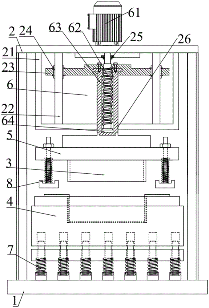
Fig. 1 is a schematic structural view of a quick and efficient edge trimmer with a positioning structure according to the present invention;
fig. 2 is a schematic structural view of the trimming punch, the punch connecting plate and a set of trimming positioning assemblies of the present invention;
fig. 3 is a top view of the trimming base of the present invention;
figure 4 is the utility model discloses a structure schematic diagram of side cut base buffering subassembly.
Detailed Description
Reference will now be made in detail to embodiments of the present invention, examples of which are illustrated in the accompanying drawings, wherein like reference numerals refer to the same or similar elements or elements having the same or similar function throughout. The embodiments described below with reference to the drawings are exemplary and intended to be used for explaining the present invention, and should not be construed as limiting the present invention.
In the description of the present invention, it is to be understood that the terms "center", "longitudinal", "lateral", "length", "width", "thickness", "upper", "lower", "front", "rear", "left", "right", "vertical", "horizontal", "top", "bottom", "inner", "clockwise", "counterclockwise" and the like indicate orientations or positional relationships based on the orientations or positional relationships shown in the drawings, and are only for convenience of description and to simplify the description, but do not indicate or imply that the device or element referred to must have a particular orientation, be constructed and operated in a particular orientation, and therefore should not be construed as limiting the present invention.
Furthermore, the terms "first", "second" and "first" are used for descriptive purposes only and are not to be construed as indicating or implying relative importance or implicitly indicating the number of technical features indicated. Thus, a feature defined as "first" or "second" may explicitly or implicitly include one or more of that feature. In the description of the present invention, unless otherwise specified, "a plurality" means two or more unless explicitly defined otherwise.
In the present invention, unless otherwise expressly specified or limited, the terms "mounted," "connected," and "fixed" are to be construed broadly and may, for example, be fixedly connected, detachably connected, or integrally connected; can be mechanically or electrically connected; they may be connected directly or indirectly through intervening media, or they may be interconnected between two elements. The specific meaning of the above terms in the present invention can be understood according to specific situations by those skilled in the art.
In the present disclosure, unless expressly stated or limited otherwise, the first feature "on" or "under" the second feature may comprise direct contact between the first and second features, or may comprise contact between the first and second features not directly. Also, the first feature being "on," "above" and "over" the second feature includes the first feature being directly on and obliquely above the second feature, or merely indicating that the first feature is at a higher level than the second feature. A first feature being "under," "below," and "beneath" a second feature includes the first feature being directly under and obliquely below the second feature, or simply meaning that the first feature is at a lesser elevation than the second feature.
Example one
As shown in fig. 1, the quick and efficient edge trimmer with the positioning structure comprises a bottom plate 1, a frame 2, an edge trimming punch 3, an edge trimming base 4, a punch connecting plate 5, a punch lifting driving assembly 6, a group of edge trimming base buffering assembly 7 and a group of edge trimming positioning assembly 8, wherein the frame 2 and the group of edge trimming base buffering assembly 7 are fixedly arranged on the bottom plate 1, the punch lifting driving assembly 6 is arranged on an upper end beam of the frame 2, the punch connecting plate 5 and the punch lifting driving assembly 6 are fixedly connected, the group of edge trimming positioning assembly 8 and the edge trimming punch 3 are arranged on the punch connecting plate 5, the edge trimming base 4 is arranged on the group of edge trimming base buffering assembly 7, the edge trimming base 4 is located under the edge trimming punch 3, and a workpiece can be arranged on the edge trimming base 4.
The trimming positioning assembly 8 shown in fig. 2 includes a stud 81, a limit nut 82, a first spring 83 and a positioning press plate 84, a set of first through holes 51 is formed in the punch connecting plate 5, the set of first through holes 51 and the set of trimming positioning assemblies 8 are arranged in a one-to-one correspondence manner, the stud 81 can pass through the first through holes 51, the limit nut 82 is in threaded connection with the upper end of the stud 81, the limit nut 82 is located above the punch connecting plate 5, the positioning press plate 84 is fixedly arranged at the lower end of the stud 81, the first spring 83 is sleeved on the stud 81, the first spring 83 is located between the lower end face of the punch connecting plate 5 and the upper end face of the positioning press plate 84, and the positioning press plate 84 can be pressed on the to-be-trimmed edge of the workpiece. The upper end face of the positioning pressing plate 84 is provided with a first spring limiting groove 85, the lower end face of the punch connecting plate 5 is provided with a second spring limiting groove 86, the upper end part of the first spring 83 is located in the second spring limiting groove 86, and the lower end part of the first spring 83 is located in the first spring limiting groove 85.
The outside of the trimming punch 3 shown in fig. 2 and 3 is provided with a trimming blade 31, and a gap 32 is provided between the trimming blade 31 and the trimming punch 3. The upper end face of the trimming base 4 is provided with a workpiece placing groove 41 and a cutter groove 42, the cutter groove 42 is sleeved outside the workpiece placing groove 41, a vertical edge 43 is arranged between the cutter groove 42 and the workpiece placing groove 41, the trimming cutter 31 can extend into the cutter groove 42, the trimming punch 3 can extend into the workpiece placing groove 41, the vertical edge 43 and the gap 32 are arranged oppositely, and the vertical edge 43 can extend into the gap 32.
The positioning pressure plate 84 can press the edge of the workpiece to be cut and push the workpiece into the workpiece placing groove 41, and as the punch lifting drive assembly 6 descends, the spring I83 is compressed, and the stud 81 moves in the through hole I51.
Example two
The punch lifting driving assembly 6 shown in fig. 1 comprises a lifting driving motor 61, a screw rod I62 and a screw rod sleeve I63, wherein the lifting driving motor 61 is fixedly arranged on a cross beam of the frame 2, the lifting driving motor 61 is connected with the screw rod I62, a cavity 64 is arranged inside the screw rod sleeve I63, the screw rod I62 extends into the cavity 64, the screw rod I62 is in threaded connection with the screw rod I62, and the punch connecting plate 5 is fixedly connected with the lower end part of the screw rod sleeve I63.
Wherein, be equipped with guide post support frame 21 on the crossbeam of frame 2, be equipped with a set of guide post 22 between the crossbeam of guide post support frame 21 and frame 2, be connected with direction slide 23 on the outer wall of screw rod cover 63, be equipped with a set of direction sliding sleeve 24 on the direction slide 23, a set of direction sliding sleeve 24 and a set of guide post 22 one-to-one set up to guide post 22 and the sliding connection of direction sliding sleeve 24. The cross beam of the frame 2 is provided with a bushing 25, the upper end of the first screw rod 62 can penetrate through the bushing 25, the lower end of the guide column support frame 21 is provided with a second through hole 26, and the lower end of the first screw rod 63 can penetrate through the second through hole 26.
EXAMPLE III
The trimming base buffer assembly 7 shown in fig. 4 comprises a fixed seat 71, a second guide column 72 and a second spring 73, wherein the fixed seat 71 is fixedly arranged on the bottom plate 1, the lower end part of the second guide column 72 is fixedly arranged on the fixed seat 71, the second spring 73 is sleeved on the second guide column 72, the second spring 73 is positioned between the fixed seat 71 and the lower end surface of the trimming base 4, a group of guide grooves 44 are arranged on the lower end surface of the trimming base 4, the group of guide grooves 44 and the group of trimming base buffer assemblies 7 are arranged in a one-to-one correspondence manner, and the upper end part of the second guide column 72 can extend into the guide grooves 44.
In the structure, the below of side cut base 4 is equipped with buffering backup pad 9, be equipped with three 91 of a set of through-hole on the buffering backup pad 9, three 91 of a set of through-hole, a set of guide way 44 and a set of side cut base buffering subassembly 7 one-to-one set up, three 91 of through-hole can be passed to the upper end of guide post two 72, spring two 73 is located between the lower terminal surface of fixing base 71 and buffering backup pad 9. A third spring limiting groove 92 is formed in the lower end face of the buffer supporting plate 9, a fourth spring limiting groove 74 is formed in the upper end face of the fixing seat 71, and the upper end portion and the lower end portion of the second spring 73 are located in the third spring limiting groove 92 and the fourth spring limiting groove 74 respectively.
When the trimming punch 3 is pressed down to treat the trimming workpiece to perform trimming, the trimming base buffer component 7 can provide certain buffer force for the trimming base 4, and hard contact between the trimming punch 3 and the trimming base 4 is avoided.
The utility model discloses the theory of operation of high efficiency bead cutter with location structure does:
the workpiece to be edge-cut is placed into the workpiece placing groove 41, due to the friction force between the workpiece with the edge-cut and the inner wall of the workpiece placing groove 41, the workpiece with the edge-cut is in an inclined state in the workpiece placing groove 41, the lifting driving motor 61 drives the screw rod I62 to rotate, the screw rod I62 rotates to drive the screw rod sleeve I63 to move along the vertical direction, the edge-cutting punch 3 and the punch connecting plate 5 are driven to descend, the punch connecting plate 5 descends, the group of edge-cutting positioning components 8 synchronously drive the punch connecting plate 5 to descend, when the positioning pressing plate 84 contacts the edge of the workpiece with the edge-cut, the punch connecting plate 5 descends continuously, the positioning pressing plate 84 applies a certain pressure on the workpiece with the edge-cut due to the descending of the punch connecting plate 5, so that the workpiece to be edge-cut is pressed into the workpiece placing groove 41, the edge-cutting punch 3 descends continuously along with the driving of the punch lifting driving component 6, and cutting the edge of the workpiece to be cut.
The foregoing is only a preferred embodiment of the present invention, and it should be noted that, for those skilled in the art, a plurality of modifications can be made without departing from the principles of the present invention, and these modifications should also be regarded as the protection scope of the present invention.