A hide and hold structure for drawer
Technical Field
The utility model relates to a hidden bearing structure for a drawer.
Background
Chinese patent document No. CN111086803A discloses a drawer-type hidden trash can in 5/1/2020, which comprises a trash can, a flat plate, a drawer guide rail and a connecting device, wherein the connecting device is either an L-shaped corner brace or a batten. The structure is characterized in that the garbage can, the flat plate and the drawer guide rail are combined into a whole, and the garbage can is hidden in an empty space below a bottom plate of the furniture and is pulled out when in use, so that two defects of stumbling and unsightly of the garbage can placed in a room to people are eliminated; however, the space in the kitchen is not of uniform size, and the size of drawer all designs according to the space in the kitchen, and the size of garbage bin is not of uniform size simultaneously, and the drawer size of above-mentioned structure is fixed, can only be used for single size's garbage bin to conceal, and its use limitation is great, and the garbage bin also can only be placed the fixed position at the drawer simultaneously, and the flexibility is relatively poor, can't satisfy user's user demand. Therefore, further improvements are necessary.
SUMMERY OF THE UTILITY MODEL
The utility model aims at providing a hide and hold structure of putting for drawer to overcome prior art well drawer size fixed, can only hide the weak point of holding to single size household utensils.
A hide and hold structure for drawer according to this purpose design, the drawer is including controlling the curb plate that sets up at least, its characterized in that: the lower parts of the left and right side plates are respectively provided with a left supporting part and a right supporting part in an integral bending or split mode, a bearing and placing device is arranged between the left supporting part and the right supporting part, and at least one bearing and placing area used for bearing and placing devices is arranged on the bearing and placing device.
The bearing device comprises a left base, a right base, at least two telescopic rod assemblies and at least one movable rod assembly; wherein, left base support is on left bearing portion, and right base support is on right bearing portion, and two at least telescopic link subassemblies are set up around being, and both ends respectively with left base, right base fixed connection, and at least one movable rod subassembly is located between two at least telescopic link subassemblies.
The movable rod assembly and/or the front and rear telescopic rod assemblies are provided with connecting rods, and the connecting rods are longitudinally arranged on the movable rod assembly and/or the front and rear telescopic rod assemblies and transversely slide on the movable rod assembly and/or the front and rear telescopic rod assemblies so as to at least realize that the transverse size of the bearing area is adjustable.
The connecting rods are respectively and longitudinally arranged on the movable rod assembly and the front and rear telescopic rod assemblies; the movable rod component slides between the front telescopic rod component and the rear telescopic rod component longitudinally through the connecting rod, so that the longitudinal size of the bearing area can be adjusted.
Sliding parts are respectively arranged on the front telescopic rod component and the rear telescopic rod component and the movable rod component; the connecting rod is positioned above the front and back telescopic rod assemblies and the movable rod assembly and is detachably arranged on the sliding piece.
The sliding piece slides with the front and back telescopic rod components and the movable rod component in a mutually transverse guiding way; the connecting rod slides on the front and back telescopic rod component and the movable rod component through the sliding component in the transverse direction, so that the transverse size of the bearing area can be adjusted.
Positioning pieces are arranged among the sliding piece, the front telescopic rod assembly, the rear telescopic rod assembly and the movable rod assembly; the sliding piece slides with the front and back telescopic rod components and the movable rod component in a mutual transverse guiding way, and the positioning of the mutual transverse sliding positions is realized through the positioning piece.
The connecting rod and the sliding piece mutually longitudinally guide and slide; the movable rod assembly slides longitudinally between the front telescopic rod assembly and the rear telescopic rod assembly through the matching of the connecting rod and the sliding piece, so that the longitudinal size of the bearing area can be adjusted.
The sliding piece is provided with a clamping part; the connecting rod is detachably clamped on the clamping part of the sliding part and longitudinally guides and slides with the sliding part.
The connecting rod, the front telescopic rod assembly and the rear telescopic rod assembly and/or the movable rod assembly at least support and act on the left base and the right base when being stressed.
The at least two telescopic rod components respectively comprise a left cross rod, a right cross rod and a middle cross rod; the outer end of the left cross rod is supported on the left base and fixedly connected with the left base, and the inner end of the left cross rod is in positioning type sliding sleeve joint with one end of the middle cross rod; the outer end of the right cross rod is supported on the right base and fixedly connected with the right base, and the inner end of the right cross rod is in positioning type sliding sleeve connection with the other end of the middle cross rod so as to realize that the transverse size of the supporting area is adjustable.
The movable rod assembly comprises a left movable rod, a right movable rod and a middle movable rod; the inner end of the left movable rod is in positioning type sliding sleeve joint with one end of the middle movable rod; the inner end of the right movable rod is in positioning type sliding sleeve connection with the other end of the middle movable rod.
Sliding parts are respectively arranged on the front and back left cross rods, the front and back right cross rods, the left movable rod and the right movable rod in a transverse guiding and sliding mode.
The connecting rod is arranged on the sliding piece and transversely slides on the front and back telescopic rod component and the movable rod component through the sliding piece so as to realize that the transverse size of the bearing area can be adjusted.
The movable rod assembly slides longitudinally between the front telescopic rod assembly and the rear telescopic rod assembly through the matching of the connecting rod and the sliding piece, so that the longitudinal size of the bearing area can be adjusted.
The utility model discloses an improvement of above-mentioned structure, compared with the prior art, has following advantage:
1. the left and right supporting parts are integrally bent or separately arranged at the lower parts of the left and right side plates respectively, the bearing device is arranged between the left and right supporting parts in a mode from top to bottom, the longitudinal bearing mode of the bearing device is quick, convenient, efficient and flexible, and a user can also detach the bearing device at will or place the bearing device between the left and right side plates according to actual use requirements, so that the use experience of the user is improved.
2. The bearing device is provided with at least one bearing area, the bearing area is composed of a left base, a right base, at least two telescopic rod components arranged in the front and back directions and a movable rod component positioned between the front and back telescopic rod components, and the movable rod component and/or the front and back telescopic rod components are provided with a connecting rod which can transversely slide on the movable rod component and/or the front and back telescopic rod components to at least realize the transverse size adjustability of the bearing area, so that a user can adjust the transverse size of the bearing area when in use to position and bear devices with different sizes, the same size and/or different positions, the user can adjust the transverse size of the bearing area at any time according to the actual use requirement to meet various bearing requirements of various devices, thereby effectively avoiding the size fixation of the drawer in the prior art, the device with single size can be placed or the placing position is fixed, thereby improving the flexibility of the device.
3. The two ends of the front telescopic rod component and the rear telescopic rod component are fixedly connected with the left base and the right base respectively, and meanwhile, the positioning type transverse sliding can be realized, so that the transverse size adjustment of the whole bearing device can be realized, the bearing device can be further promoted to be suitable for drawers with different inner widths to use, and the use flexibility and the application range of the bearing device are improved.
4. The movable rod component can slide longitudinally between the front telescopic rod component and the rear telescopic rod component at least through the connecting rod, so that the longitudinal size adjustment of the bearing area can be realized, the transverse size of the bearing area can be adjusted, and further, devices with different sizes and/or the same size can be positioned and placed on the bearing areas with different sizes and/or the same size and/or different positions, great convenience is provided for a user to bear the devices, and the use experience of the user and the bearing flexibility of the devices are further improved.
Comprehensively, the device has the characteristics of simple and reasonable structure, quick and convenient assembly, low manufacturing cost, good concealment of device placement, wide application range, high flexibility and the like, and is high in practicability
Drawings
Fig. 1 is an exploded schematic view of a drawer and a supporting device according to a first embodiment of the present invention.
Fig. 2 is a schematic view of an assembly structure of a drawer and a holding device according to a first embodiment of the present invention.
Fig. 3 and 4 are schematic exploded structural views of a supporting device according to a first embodiment of the present invention.
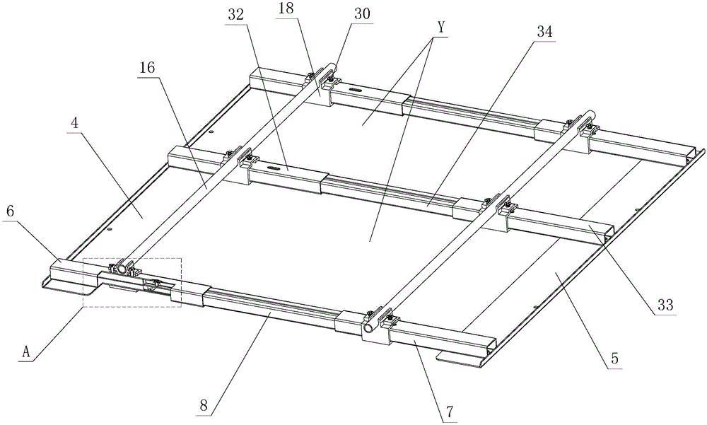
Fig. 5 and 6 are schematic views of an assembly structure of the bearing device according to the first embodiment of the present invention.
Fig. 7 is an enlarged schematic view of a portion a in fig. 5.
Fig. 8 is a schematic view of the device.
FIG. 9 is a schematic view of the adjustment of the carrying area of the carrying device.
Fig. 10 is another containment schematic of the device.
Fig. 11 is an exploded view of a drawer and a supporting device according to a second embodiment of the present invention.
Fig. 12 is a schematic view of an assembly structure of a drawer and a holding device according to a second embodiment of the present invention.
Detailed Description
The present invention will be further described with reference to the accompanying drawings and examples.
First embodiment
Referring to fig. 1-10, the hidden holding structure for a drawer at least comprises a left side plate 1 and a right side plate 1, wherein a left supporting part 2 and a right supporting part are respectively arranged at the lower parts of the left side plate 1 and the right side plate 1 in an integrally bent or separated manner, and the left supporting part 2 and the right supporting part of the embodiment are preferably integrally bent at the lower parts of the left side plate 1 and the right side plate 1.
A bearing device X is arranged between the left supporting part 2 and the right supporting part, and at least one bearing area Y for bearing the device 3 is arranged on the bearing device X.
The left and right supporting parts are integrally bent or separately arranged at the lower parts of the left and right side plates 1 respectively, the bearing device X is arranged between the left and right supporting parts in a mode from top to bottom, the longitudinal bearing mode of the bearing device X is rapid, convenient, efficient and flexible, a user can also detach the bearing device X at will or place the bearing device X between the left and right side plates 1 according to actual use requirements, and the use experience of the user is improved
The bearing device X comprises a left base 4, a right base 5, at least two telescopic rod assemblies and at least one movable rod assembly; wherein, left base 4 supports on left side support portion 2, and right base 5 supports on right support portion, and two at least telescopic link subassemblies are set up around being, and both ends respectively with left base 4, 5 fixed connection of right base, and at least one movable rod subassembly is located between two at least telescopic link subassemblies.
The two ends of the front telescopic rod component and the rear telescopic rod component are fixedly connected with the left base 4 and the right base 5 respectively, and meanwhile, the positioning type transverse sliding can be realized, so that the transverse size adjustment of the whole bearing device X can be realized, and the bearing device X can be suitable for drawers with different inner widths to be used, so that the use flexibility and the application range of the bearing device X are improved.
The connecting rod 16 is arranged on the movable rod component and/or the front telescopic rod component and/or the rear telescopic rod component, and the connecting rod 16 is longitudinally arranged on the movable rod component and/or the front telescopic rod component and/or the rear telescopic rod component and transversely slides on the movable rod component and/or the front telescopic rod component and the rear telescopic rod component so as to at least realize that the transverse size of the bearing area Y is adjustable.
The bearing area Y is composed of a left base 4, a right base 5, at least two telescopic rod components arranged in the front and back directions, and a movable rod component positioned between the front and back telescopic rod components, meanwhile, the movable rod component and/or the front and back telescopic rod components are provided with a connecting rod 16, the connecting rod 16 can transversely slide on the movable rod component and/or the front and back telescopic rod components to at least realize that the transverse size of the bearing area Y can be adjusted, so that a user can adjust the transverse size of the bearing area Y when in use to position and bear the devices 3 with different sizes, and/or the same size, and/or different positions, the user can adjust the transverse size of the bearing area Y at any time according to the actual use requirement to meet various bearing requirements of various devices 3, thereby effectively avoiding the size fixation of the drawer in the prior art, the device 3 with single size can be placed or the placing position is fixed, thereby improving the flexibility of placing the device 3.
The connecting rods 16 are respectively and longitudinally arranged on the movable rod assembly and the front and rear telescopic rod assemblies; the movable rod assembly slides longitudinally between the front and rear telescopic rod assemblies through the connecting rod 16, so that the longitudinal size of the bearing area Y can be adjusted.
The moving rod assembly can slide longitudinally between the front telescopic rod assembly and the rear telescopic rod assembly at least through the connecting rod 16, so that the longitudinal size adjustment of the bearing area Y can be realized, the transverse size adjustment of the bearing area Y is matched, and further, devices 3 with different sizes and/or the same size can be positioned and placed on the bearing areas Y with different sizes and/or the same size and/or different positions, great convenience is provided for users to bear and place the devices 3, and the use experience of the users and the bearing flexibility of the devices are further improved.
Specifically, the front and rear telescopic rod assemblies and the movable rod assembly are respectively provided with a sliding member 18; the connecting rod 16 is positioned above the front and rear telescopic rod assemblies and the movable rod assembly and is detachably arranged on the sliding piece 18.
The sliding part 18, the front telescopic rod assembly, the rear telescopic rod assembly and the movable rod assembly slide in a mutually transverse guiding way; the connecting rod 16 transversely slides on the front and rear telescopic rod assemblies and the movable rod assembly through the sliding piece 18, so that the transverse size of the bearing area Y can be adjusted.
Positioning pieces 30 are arranged among the sliding piece 18, the front telescopic rod assembly, the rear telescopic rod assembly and the movable rod assembly; the sliding part 18 slides with the front and back telescopic rod assemblies and the movable rod assembly in a mutually transverse guiding way, and the positioning of the mutual transverse sliding position is realized through the positioning part 30.
The connecting rod 16 and the sliding piece 18 mutually longitudinally slide; the movable rod assembly slides longitudinally between the front telescopic rod assembly and the rear telescopic rod assembly through the matching of the connecting rod 16 and the sliding piece 18, so that the longitudinal size of the bearing area Y can be adjusted.
The sliding part 18 is provided with a clamping part 31; the connecting rod 16 is detachably clamped on the clamping part 31 of the sliding part 18 and longitudinally guides and slides with the sliding part 18.
The connecting rod 16, and/or the front and rear telescopic rod assemblies, and/or the movable rod assembly support the left base 4 and the right base 5 at least when stressed.
The at least two telescopic rod components respectively comprise a left cross rod 6, a right cross rod 7 and a middle cross rod 8; the outer end of the left cross rod 6 is supported on the left base 4 and fixedly connected with the left base 4, and the inner end of the left cross rod 6 is in positioning type sliding sleeve joint with one end of the middle cross rod 8; the outer end of the right cross rod 7 is supported on the right base 5 and fixedly connected with the right base, and the inner end of the right cross rod 7 is in positioning type sliding sleeve connection with the other end of the middle cross rod 8 so as to realize that the transverse size of the supporting area Y can be adjusted.
The movable bar assembly includes a left movable bar 32, a right movable bar 33, and an intermediate movable bar 34; the inner end of the left movable rod 32 is sleeved with one end of the middle movable rod 34 in a positioning type sliding manner; the inner end of the right movable rod 33 is sleeved with the other end of the middle movable rod 34 in a positioning type sliding manner.
The front and back left cross bar 6, the front and back right cross bar 7, the left movable rod 32 and the right movable rod 33 are respectively provided with a sliding part 18 in a transverse guiding and sliding way.
The connecting rod 16 is arranged on a sliding piece 18 and transversely slides on the front telescopic rod assembly, the rear telescopic rod assembly and the movable rod assembly through the sliding piece 18 so as to realize that the transverse dimension of the bearing area Y is adjustable.
The movable rod assembly slides longitudinally between the front and rear telescopic rod assemblies through the cooperation of the connecting rod 16 and the sliding piece 18, so that the longitudinal size of the bearing area Y can be adjusted.
The transverse size of the bearing area Y and the longitudinal size of the bearing area Y can be adjusted independently or synchronously, so that the use experience of a user is improved.
In the drawer of the present embodiment, as shown in fig. 1 and 2, the left and right side plates 1 are flat and have vertical inner sides, so that the receiving device X can be received between the left and right support portions 2 and 2 from top to bottom. The front and rear ends of the left and right side plates 1 are respectively and integrally bent with a front bending part and a rear bending part, and are respectively and fixedly connected with a front plate and a rear plate through the front bending part and the rear bending part.
Second embodiment
Referring to fig. 11 and 12, the hidden receiving structure for a drawer differs from the first embodiment in that: the left and right side plates 1 are respectively provided with a cavity part, the inner sides of the cavity parts are vertical, so that the bearing device X can be arranged between the left bearing part 2 and the right bearing part from top to bottom. The front and rear ends of the cavity part of the left and right side plates 1 are respectively provided with a front connecting device and a rear connecting device, and are fixedly connected with a front plate and a rear plate respectively through the front connecting device and the rear connecting device.
The other parts not described are the same as those of the first embodiment.
The foregoing is a preferred embodiment of the present invention showing and describing the basic principles, main features and advantages of the present invention. It will be understood by those skilled in the art that the present invention is not limited to the embodiments described above, which are intended to illustrate the principles of the invention, but rather that various changes and modifications may be made without departing from the spirit and scope of the invention, the scope of which is defined by the appended claims and their equivalents.