SUMMERY OF THE UTILITY MODEL
An object of the utility model is to provide a multi-purpose measuring tool, this multi-purpose measuring tool can solve the unable measurement of conventional measuring tool, and high-tech equipment is expensive, problem consuming time and wasting force.
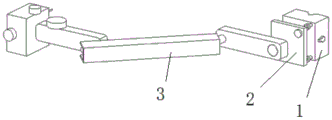
The utility model provides a multi-purpose measuring tool, include: the device comprises a base, a first adjusting platform and a second adjusting platform, wherein the first adjusting platform is arranged above the base and adjusts the upper end face to be horizontal; the first adjusting platform is connected with a first support arm, and one end of the first support arm, which is far away from the first adjusting platform, is connected with a second support arm; one end of the second support arm, which is far away from the first support arm, is connected with a second adjusting platform; and a dial indicator is arranged on the second adjusting platform.
Wherein, the base is a magnetic base.
The first adjusting platform is a horizontal adjusting platform with a horizontal bubble in the middle; the first adjusting platform is connected with the base through a plurality of adjusting supports.
The first support arm is vertically and rotatably connected with the first adjusting platform.
Wherein, the second support arm with first support arm horizontal rotation is connected.
And a slope fixed rack is arranged in the second support arm.
The second adjusting platform is a distance adjusting platform capable of displaying the moving size.
The second adjusting platform is a distance adjusting platform which can move vertically and move relative to the second support arm in the horizontal direction.
Wherein, the dial indicator is a digital display dial indicator.
The utility model relates to a multi-purpose measuring tool beneficial effect: adjust its terminal surface to the level through first adjustment platform for the first support arm of being connected with first adjustment platform can carry out the direction and adjust, and the second support arm can vertical removal and the distance adjustment platform of second support arm horizontal direction removal relatively, and then be equipped with on the second adjustment platform amesdial and can obtain measurement and the rapid survey that the accuracy is high.
Detailed Description
The technical solution of the present invention will be described clearly and completely with reference to the following embodiments, and it should be understood that the described embodiments are some, but not all embodiments of the present invention. Based on the embodiments in the present invention, all other embodiments obtained by a person skilled in the art without creative work belong to the protection scope of the present invention.
In the description of the present invention, it is to be understood that the terms "center", "longitudinal", "lateral", "length", "width", "thickness", "upper", "lower", "front", "rear", "left", "right", "vertical", "horizontal", "top", "bottom", "inner", "outer", "clockwise", "counterclockwise", and the like indicate orientations or positional relationships based on the orientations or positional relationships shown in the drawings, and are only for convenience of description and to simplify the description, but do not indicate or imply that the device or element referred to must have a particular orientation, be constructed and operated in a particular orientation, and therefore should not be construed as limiting the present invention.
Furthermore, the terms "first", "second" and "first" are used for descriptive purposes only and are not to be construed as indicating or implying relative importance or implicitly indicating the number of technical features indicated. Thus, features defined as "first", "second", may explicitly or implicitly include one or more of the described features. In the description of the present invention, "a plurality" means two or more unless specifically limited otherwise. Furthermore, the terms "mounted," "connected," and "connected" are to be construed broadly and may, for example, be fixedly connected, detachably connected, or integrally connected; can be mechanically or electrically connected; they may be connected directly or indirectly through intervening media, or they may be interconnected between two elements. The specific meaning of the above terms in the present invention can be understood in specific cases to those skilled in the art.
Referring to fig. 1-3, a multi-purpose measuring tool includes: the device comprises a base 1, a first adjusting platform 2 and a second adjusting platform 2, wherein the upper end face of the first adjusting platform 2 is adjusted to be horizontal; the first adjusting platform 2 is connected with a first support arm 3, and one end of the first support arm 3, which is far away from the first adjusting platform 2, is connected with a second support arm 4; one end of the second support arm 4, which is far away from the first support arm 3, is connected with a second adjusting platform 5; and a dial indicator 6 is arranged on the second adjusting platform 5.
The base 1 is a magnetic base 1, the magnetic base 1 is fixed, a measuring head 7 of a digital display dial indicator 6 is moved to a required measuring position through a first support arm 3, a vertical direction knob below the first support arm 3 is rotated to fix the vertical direction, after the left direction and the right direction are adjusted, a horizontal direction knob below the first support arm 3 is rotated to fix the left direction and the right direction, the front direction and the back direction are adjusted through a knob on a second support arm 4, then the digital display dial indicator 6 is controlled to move up and down through adjusting a knob above a second adjusting platform 5, the pressing amount of the measuring head 7 below the dial indicator 6 is adjusted, the distance of vertical displacement can be recorded on a digital display screen on a small-distance adjusting platform (the second adjusting platform 5 is a small-distance adjusting platform with small distance adjustment), and therefore the distance of the measuring head 7 moving towards the measuring area direction is ensured to be consistent; if the levelness needs to be measured, the knob on the side of the small-distance adjusting table can be directly rotated in a short distance, the digital display dial indicator 6 is controlled to move left and right, and the distance of left and right displacement can be recorded on a digital display screen on the small-distance adjusting table; if the measured horizontal length is very long, the knob fixed in the horizontal direction below the first support arm 3 can be loosened, the position is directly moved to the position nearby, and the position is adjusted to be exact through the second support arm 4 (if a bulge exists in the midway, the measuring head 7 of the digital display dial indicator 6 can be lifted up through the knob above the small-distance adjusting table, and the position is recovered to the original position after the measuring head reaches the specified position). The method can be automatically adjusted according to the specific measurement requirements.
Small distance adjusting stages are known in the art.
Specifically, the first adjusting platform 2 is a horizontal adjusting platform with a horizontal bubble in the middle; the first adjusting platform 2 is connected with the base 1 through a plurality of adjusting supports.
First adjustment platform 2 adopts three point support for the horizontal adjustment platform that has the bubble, through the height of adjusting three supports, transfers the bubble to central authorities, guarantees that the installation benchmark of instrument is unanimous with the earth's axis, has solved under the condition that does not have the reference surface, the alignment problem of instrument self benchmark.
Specifically, the first arm 3 is rotatably connected to the first adjustment platform 2 and fastened by a horizontal knob.
The connection mode of the first support arm 3, the first adjusting platform 2 and the second support arm 4 has the characteristics of convenient movement and firm fixation. The position that needs the measurement is reachd fast to gauge head 7, has two knobs below first support arm 3, and one of them vertical direction knob is used for locking 3 vertical directions of first support arm, and another horizontal direction knob is used for locking the horizontal direction, the utility model discloses when using, arrange gauge head 7 in through first support arm 3 and measure regionally, lock vertical direction and horizontal direction knob, when surveying the symmetry, measure a point after, loosen horizontal knob, remove 7 to next point of gauge head and measure can.
Specifically, the second support arm 4 is rotatably connected to the first support arm 3, and the first support arm 3 is provided with a vertical knob for fastening the first support arm 3 and the second support arm 4.
The second support arm 4 is internally provided with a slope fixing rack, so that the situation that the position of the measuring head 7 in the horizontal direction changes and the specific slope does not exist when the measuring head moves back and forth is ensured, actual measurement is carried out during assembly, the height difference of the back and forth movement is measured, and the size of the slope is determined.
Specifically, a slope fixing rack is arranged in the second support arm 4.
The slope fixed rack is a conventional structure, and belongs to the prior art. The technology applies the gradient fixed rack to the technology.
When the second support arm 4 moves back and forth, because the weight of the small-distance adjusting table and the dial indicator 6 can cause the phenomenon of end head lowering in the moving process, the phenomenon cannot be avoided in high-precision measurement, the slope fixing rack is not parallel to the earth axis, but the tooth surface end has a certain slope, the specific slope is determined by adopting a method combining theoretical calculation and actual measurement due to the existence of variables, the installation is carried out through the slope calculated theoretically, and the slope of the slope fixing rack is adjusted to a proper angle through the result of actual measurement.
Specifically, the second adjustment platform 5 is a distance adjustment table capable of displaying the movement size.
The second adjusting platform 5 can move in the vertical direction and the left-right direction for the small-distance adjusting platform, the moving size can be displayed, and the consistency of the measuring area is guaranteed.
Specifically, the second adjusting platform 5 is a distance adjusting platform capable of moving vertically and moving horizontally relative to the second support arm 4.
The second adjusting platform 5 is a small-distance adjusting platform, the movement in the vertical direction and the left-right direction is transmitted in a mechanical mode of matching a high-precision lead screw and a nut, the displacement in the vertical direction and the left-right direction is displayed through a digital display screen, the precision is 0.02mm, and the power supply mode of the second adjusting platform 5 is the power supply mode of a button battery.
Specifically, the dial indicator 6 is a digital display dial indicator.
The dial indicator 6 is a digital display dial indicator, and the measurement precision and the measurement of the wide-range size are guaranteed.
The fastening manner of the vertical direction knob and the horizontal direction knob in the present technology is a conventional structure, and is utilized in the present technology.
Finally, it should be noted that: the above embodiments are only used to illustrate the technical solution of the present invention, and not to limit the same; although the present invention has been described in detail with reference to the foregoing embodiments, it should be understood by those skilled in the art that: the technical solutions described in the foregoing embodiments may still be modified, or some or all of the technical features may be equivalently replaced; such modifications and substitutions do not depart from the spirit and scope of the present invention.