CN213840027U - High pressure resistant check valve - Google Patents
High pressure resistant check valve Download PDFInfo
- Publication number
- CN213840027U CN213840027U CN202022656979.1U CN202022656979U CN213840027U CN 213840027 U CN213840027 U CN 213840027U CN 202022656979 U CN202022656979 U CN 202022656979U CN 213840027 U CN213840027 U CN 213840027U
- Authority
- CN
- China
- Prior art keywords
- check valve
- valve body
- ring
- movable
- high pressure
- Prior art date
- Legal status (The legal status is an assumption and is not a legal conclusion. Google has not performed a legal analysis and makes no representation as to the accuracy of the status listed.)
- Active
Links
- 230000002093 peripheral effect Effects 0.000 claims abstract description 22
- 244000309464 bull Species 0.000 claims abstract description 11
- 238000007789 sealing Methods 0.000 claims abstract description 8
- 229910000831 Steel Inorganic materials 0.000 claims description 8
- 239000010959 steel Substances 0.000 claims description 8
- 230000000149 penetrating effect Effects 0.000 claims description 6
- 238000005096 rolling process Methods 0.000 claims description 3
- 230000000694 effects Effects 0.000 abstract description 3
- 238000009434 installation Methods 0.000 description 4
- 230000007547 defect Effects 0.000 description 2
- 238000011900 installation process Methods 0.000 description 2
- 238000000034 method Methods 0.000 description 2
- FGRBYDKOBBBPOI-UHFFFAOYSA-N 10,10-dioxo-2-[4-(N-phenylanilino)phenyl]thioxanthen-9-one Chemical compound O=C1c2ccccc2S(=O)(=O)c2ccc(cc12)-c1ccc(cc1)N(c1ccccc1)c1ccccc1 FGRBYDKOBBBPOI-UHFFFAOYSA-N 0.000 description 1
- 230000005540 biological transmission Effects 0.000 description 1
- 238000002955 isolation Methods 0.000 description 1
- 238000005086 pumping Methods 0.000 description 1
- 238000010992 reflux Methods 0.000 description 1
- 230000003252 repetitive effect Effects 0.000 description 1
Images



Landscapes
- Check Valves (AREA)
Abstract
The utility model discloses an anti high pressure check valve, including the check valve body, the equal cover in check valve body both sides outer peripheral face is equipped with first retainer plate, two all run through between the first retainer plate top and between the bottom and be provided with the bull stick, check valve body one side is provided with the activity circle, activity circle top and bottom are all fixed to be embedded into has the internal thread bush. The utility model discloses a establish the fixed sleeve cover in a pipeline outside, clockwise rotation ring gear drives the movable sleeve and realizes with check valve body sealing connection between two pipelines to the left side removal, and four nuts realize fixing two bull sticks and left first retainer plate, avoid the ring gear rotation to the realization is fixed the setting between two pipelines with the check valve body, and it is convenient to install, and the anticlockwise rotation ring gear is convenient for dismantle the check valve body from between two pipelines, and the dismouting of check valve body is convenient, and the practicality is stronger.
Description
Technical Field
The utility model relates to a check valve technical field, concretely relates to anti high pressure check valve.
Background
The check valve is a valve whose opening and closing member is a circular valve flap and can be actuated by self-weight and medium pressure to block back flow of medium, belonging to the field of automatic valve, also called check valve, one-way valve, reflux valve or isolating valve, and its valve flap movement mode can be divided into lift type and swing type, the lift type check valve is similar to the structure of stop valve, and only lacks valve rod for driving valve flap, the medium can be flowed in from inlet end (lower side) and flowed out from outlet end (upper side), when the inlet pressure is greater than sum of valve flap weight and its flow resistance, the valve can be opened, otherwise, when the medium is back-flowed, the valve is closed, the swing type check valve has a valve flap which is obliquely placed and can be rotated around shaft, its working principle is similar to that of lift type check valve, and its check valve can be used as bottom valve of water-pumping equipment, and can be combined with stop valve, and can play the role of safety isolation, and its defect is large resistance, the sealing performance is poor when the valve is closed, and most of the existing high-pressure-resistant check valves are arranged between two pipelines for use.
The prior art has the following defects: most of the existing high-pressure-resistant check valves are installed between two pipelines through various clamp matching bolts, and the clamp and the bolt are complex in installation process and need to be located and installed before the check valve during installation, so that the check valve is inconvenient to install, and the practicability of the check valve is poor.
The above information disclosed in this background section is only for enhancement of understanding of the background of the disclosure and therefore it may contain information that does not constitute prior art that is already known to a person of ordinary skill in the art.
SUMMERY OF THE UTILITY MODEL
The utility model aims at providing an anti high pressure check valve, through establishing the fixed sleeve cover in a pipeline outside, clockwise rotation ring gear drives the movable sleeve pipe and realizes between two pipelines with check valve body sealing connection to the left side removal, four nuts realize fixing two bull sticks and left first retainer plate, avoid the ring gear rotation, thereby realize with the fixed setting of check valve body between two pipelines, it is convenient to install, the anticlockwise rotation ring gear is convenient for dismantle the check valve body from between two pipelines, check valve body dismouting is convenient, the practicality is stronger, in order to solve the problem among the above-mentioned background art.
In order to achieve the above object, the present invention provides the following technical solutions: the high-pressure resistant check valve comprises a check valve body, wherein first fixing rings are sleeved on the outer peripheral surfaces of two sides of the check valve body, rotating rods are arranged between the tops of the two first fixing rings and between the bottoms of the two first fixing rings in a penetrating manner, a movable ring is arranged on one side of the check valve body, internal thread sleeves are fixedly embedded in the tops and the bottoms of the movable rings, the two rotating rods are respectively arranged in the internal thread sleeves at corresponding positions in a penetrating manner, a movable sleeve is arranged on one side of the check valve body close to the movable ring, the outer peripheral surface of the movable sleeve is fixedly connected with the inner peripheral surface of the movable ring, two nuts are arranged on two sides of the first fixing rings close to the movable rings, the four nuts are respectively sleeved outside the rotating rods at corresponding positions, a fixing sleeve is fixedly sleeved on one side of the check valve body far, the check valve body is close to the fixed sleeve one side outer peripheral face and is fixedly provided with two second retainer rings, is provided with the ring gear between two the second retainer rings, and two the bull stick is kept away from the one side of movable circle and all fixedly is provided with the gear, two the gear all meshes with the ring gear mutually.
Preferably, a plurality of arc-shaped grooves are fixedly formed in the opposite ends of the two second fixing rings, steel balls are arranged in the arc-shaped grooves in a rolling mode, and the steel balls are attached to the inner gear ring.
Preferably, the joints of the two rotating rods and the first fixing rings corresponding to the positions are provided with bearings, and the two rotating rods are rotatably connected with the first fixing rings corresponding to the positions through the bearings.
Preferably, two one side that the bull stick is close to the movable ring all fixedly is provided with the external screw thread, two internal thread cover and four nuts threaded connection respectively correspond the bull stick outside of position.
Preferably, a first rubber ring is fixedly arranged on the inner peripheral surface of the movable sleeve, and the movable sleeve is hermetically connected with one side, close to the movable ring, of the check valve body through the first rubber ring.
Preferably, two one end that the retaining ring carried on the back mutually all is fixed and is provided with the second rubber circle.
Preferably, the outer peripheral surface of the inner gear ring is fixedly provided with a plurality of shifting blocks.
In the technical scheme, the utility model provides a technological effect and advantage:
the check valve body is sleeved outside one pipeline by the fixed sleeve, the dial block is clockwise dialed to drive the inner gear ring to rotate clockwise, the two rotating rods are further driven to rotate simultaneously, the two rotating rods drive the two inner thread sleeves and the movable ring to move leftwards simultaneously when rotating, the movable ring further drives the movable sleeve to move leftwards so as to realize that the check valve body is erected between the two pipelines, the inner gear ring is continuously rotated to drive the movable sleeve to move leftwards so as to ensure that the two pipelines are tightly attached to check rings at corresponding positions, the two second sealing rings realize the sealing connection of the check valve body between the two pipelines, the two nuts at corresponding positions are moved towards the middle part, the two rotating rods are fixed with the first fixed ring at the left side through the four nuts to avoid the inner gear ring, thereby realizing the fixed arrangement of the check valve body between the two pipelines, realizing the installation of the check valve body, and being convenient to install the check valve body, two nuts corresponding to the positions are screwed to two sides respectively, and the inner gear ring is rotated anticlockwise, so that the check valve body can be conveniently disassembled from two pipelines, the check valve body is convenient to disassemble and assemble, and the practicability is high.
Drawings
In order to more clearly illustrate the embodiments of the present application or the technical solutions in the prior art, the drawings needed to be used in the embodiments will be briefly described below, and it is obvious that the drawings in the following description are only some embodiments described in the present invention, and other drawings can be obtained by those skilled in the art according to these drawings.
Fig. 1 is a schematic view of the overall structure of the present invention.
Fig. 2 is an enlarged view of a portion a of fig. 1 according to the present invention.
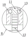
Fig. 3 is an enlarged view of a portion B of fig. 1 according to the present invention.
Fig. 4 is a view of the usage scenario of fig. 1 according to the present invention.
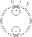
Fig. 5 is a left side view of the gear and the ring gear of the present invention.
Description of reference numerals:
1. a check valve body; 2. a first retainer ring; 3. a rotating rod; 4. a movable ring; 5. an internal thread sleeve; 6. an active cannula; 7. a nut; 8. fixing the sleeve; 9. a retainer ring; 10. a second retainer ring; 11. an inner gear ring; 12. a gear; 13. and (5) steel balls.
Detailed Description
Example embodiments will now be described more fully with reference to the accompanying drawings. Example embodiments may, however, be embodied in many different forms and should not be construed as limited to the examples set forth herein; rather, these example embodiments are provided so that this disclosure will be thorough and complete, and will fully convey the concept of example embodiments to those skilled in the art. The drawings are merely schematic illustrations of the present disclosure and are not necessarily drawn to scale. The same reference numerals in the drawings denote the same or similar parts, and thus their repetitive description will be omitted.
Furthermore, the described features, structures, or characteristics may be combined in any suitable manner in one or more example embodiments. In the following description, numerous specific details are provided to give a thorough understanding of example embodiments of the disclosure. One skilled in the relevant art will recognize, however, that the subject matter of the present disclosure can be practiced without one or more of the specific details, or with other methods, components, steps, and so forth. In other instances, well-known structures, methods, implementations, or operations are not shown or described in detail to avoid obscuring aspects of the disclosure.
The utility model provides a high pressure resistant check valve as shown in figures 1-5, which comprises a check valve body 1, wherein the outer peripheral surfaces of two sides of the check valve body 1 are all sheathed with a first fixed ring 2, two rotating rods 3 are respectively arranged between the top parts and between the bottom parts of the first fixed ring 2 in a penetrating way, one side of the check valve body 1 is provided with a movable ring 4, the top parts and the bottom parts of the movable ring 4 are respectively fixedly embedded with an internal thread sleeve 5, two rotating rods 3 are respectively arranged in the internal thread sleeves 5 of corresponding positions in a penetrating way, one side of the check valve body 1 close to the movable ring 4 is provided with a movable sleeve 6, the outer peripheral surface of the movable sleeve 6 is fixedly connected with the inner peripheral surface of the movable ring 4, two nuts 7 are respectively arranged at two sides of the first fixed ring 2 close to the movable ring 4, four nuts 7 are respectively sheathed outside the rotating rods 3 of corresponding positions, one side of the check valve body 1 far away from the movable ring 4 is sheathed with a fixed sleeve 8, the check valve comprises a check valve body 1, a movable sleeve 6, a fixed sleeve 8, a check ring 6, a check ring 12 and a check ring 9, wherein the check ring 9 is fixedly arranged on the inner peripheral surfaces of the movable sleeve 6 and the fixed sleeve 8, two second fixing rings 10 are fixedly arranged on the outer peripheral surface of one side of the check valve body 1 close to the fixed sleeve 8, an inner gear ring 11 is arranged between the two second fixing rings 10, gears 12 are fixedly arranged on one sides of two rotating rods 3 far away from the movable ring 4, and the.
Further, in the above technical scheme, a plurality of arc-shaped grooves are fixedly formed in opposite ends of the two second fixing rings 10, steel balls 14 are arranged in the plurality of arc-shaped grooves in a rolling manner, the plurality of steel balls 14 are attached to the inner gear ring 11, the two second fixing rings 10 limit the inner gear ring 11, and the steel balls 14 facilitate the rotation of the inner gear ring 11.
Further, in the above technical scheme, two the junctions of the rotating rods 3 and the first fixing rings 2 corresponding to the positions are all provided with bearings, and the rotating rods 3 are all rotationally connected with the first fixing rings 2 corresponding to the positions through the bearings, so that the two rotating rods 3 are rotationally connected with the first fixing rings 2.
Further, in the above technical scheme, two one side of the rotating rod 3 close to the movable ring 4 is fixedly provided with an external thread, and the internal thread sleeve 5 and the four nuts 7 are respectively in threaded connection with the outside of the rotating rod 3 at the corresponding position, so that thread transmission is realized.
Further, in the above technical solution, a first rubber ring is fixedly arranged on the inner peripheral surface of the movable sleeve 6, and the movable sleeve 6 is hermetically connected with one side of the check valve body 1 close to the movable ring 4 through the first rubber ring, so that the movable sleeve 6 is hermetically connected with one side of the check valve body 1 close to the movable ring 4.
Further, in the above technical scheme, two 9 one ends that back on the back mutually of retaining ring all fixedly are provided with the second rubber circle, are convenient for with check valve body 1 sealing connection between two pipelines.
Further, in the above technical solution, the outer peripheral surface of the inner gear ring 11 is fixedly provided with a plurality of toggle blocks, which facilitate toggling the inner gear ring 11.
The implementation mode is specifically as follows: during actual installation, the fixed sleeve 8 is sleeved outside one pipeline, the dial block is clockwise dialed to drive the inner gear ring 11 to rotate clockwise, the two gears 12 are both meshed with the inner gear ring 11, the inner gear ring 11 drives the two rotating rods 3 to rotate simultaneously when rotating, the two inner thread sleeves 5 are respectively in threaded connection with the outer parts of the rotating rods 3 at corresponding positions, the two rotating rods 3 drive the two inner thread sleeves 5 and the movable ring 4 to move leftwards simultaneously when rotating, the movable ring 4 further drives the movable sleeve 6 to move leftwards, when the movable sleeve 6 is sleeved outside the other pipeline, the check valve body 1 is erected between the two pipelines, the inner gear ring 11 is continuously rotated to drive the movable sleeve 6 to move leftwards, so that the two pipelines are tightly attached to the check ring 9 at corresponding positions, and the check valve body 1 is hermetically connected between the two pipelines under the action of the second seal ring at corresponding positions, the two nuts 7 corresponding to the positions are moved towards the middle, the two rotating rods 3 are fixed with the first fixing ring 2 on the left side through the four nuts 7, the inner gear ring 11 is prevented from rotating, the check valve body 1 is fixedly arranged between two pipelines, the check valve body 1 is convenient to install, the two nuts 7 corresponding to the positions are respectively screwed towards two sides, the inner gear ring 11 is rotated anticlockwise, the check valve body 1 is convenient to detach from between the two pipelines, the check valve body 1 is convenient to detach and strong in practicability, the embodiment specifically solves the problem that most of the existing high-pressure-resistant check valves in the prior art are installed between the two pipelines through various hoop matching bolts, and the installation process of the hoop and the bolts is complex, and the check valve needs to be positioned and then installed firstly during installation, so that the check valve is inconvenient to install, and further, the practicability of the check valve is deteriorated.
This practical theory of operation: through establishing 8 covers of fixed sleeve pipe outside at a pipeline, clockwise rotation ring gear 11 drives movable sleeve 6 and moves realization with check valve body 1 sealing connection between two pipelines to the left side, four nuts 7 realize fixing two bull sticks 3 and left first retainer plate 2, avoid ring gear 11 rotation, thereby realize with check valve body 1 fixed setting between two pipelines, it is convenient to install, anticlockwise rotation ring gear 11 is convenient for dismantle check valve body 1 from between two pipelines, 1 dismouting of check valve body is convenient, the practicality is stronger.
While certain exemplary embodiments of the present invention have been described above by way of illustration only, it will be apparent to those of ordinary skill in the art that the described embodiments may be modified in various different ways without departing from the spirit and scope of the present invention. Accordingly, the drawings and description are illustrative in nature and should not be construed as limiting the scope of the invention.
Claims (7)
1. Anti high pressure check valve, including check valve body (1), its characterized in that: the check valve is characterized in that first fixing rings (2) are sleeved on the outer peripheral surfaces of two sides of the check valve body (1), rotating rods (3) are arranged between the tops and between the bottoms of the first fixing rings (2) in a penetrating mode, a movable ring (4) is arranged on one side of the check valve body (1), inner thread sleeves (5) are fixedly embedded in the tops and the bottoms of the movable rings (4), the two rotating rods (3) are arranged in the inner thread sleeves (5) in corresponding positions in a penetrating mode respectively, a movable sleeve (6) is arranged on one side, close to the movable ring (4), of the check valve body (1), the outer peripheral surface of the movable sleeve (6) is fixedly connected with the inner peripheral surface of the movable ring (4), two nuts (7) are arranged on two sides of the first fixing rings (2) close to the movable ring (4), and the four nuts (7) are sleeved outside the rotating rods (3) in corresponding positions respectively, the check valve is characterized in that a fixed sleeve (8) is sleeved on one side, away from the movable ring (4), of the check valve body (1), a check ring (9) is fixedly arranged on the inner peripheral surface of the movable sleeve (6) and the inner peripheral surface of the fixed sleeve (8), two second fixing rings (10) are fixedly arranged on the outer peripheral surface of one side, close to the fixed sleeve (8), of the check valve body (1), an inner gear ring (11) is arranged between the two second fixing rings (10), two gears (12) are fixedly arranged on one side, away from the movable ring (4), of the rotating rod (3), and the gears (12) are meshed with the inner gear ring (11).
2. The high pressure resistant check valve of claim 1 wherein: a plurality of arc-shaped grooves are fixedly formed in the opposite ends of the two second fixing rings (10), steel balls (14) are arranged in the arc-shaped grooves in a rolling mode, and the steel balls (14) are attached to the inner gear ring (11).
3. The high pressure resistant check valve of claim 1 wherein: two the bull stick (3) all is provided with the bearing with first retainer plate (2) junction that corresponds the position, two bull stick (3) all rotate through bearing and first retainer plate (2) that correspond the position and are connected.
4. The high pressure resistant check valve of claim 1 wherein: two one side that bull stick (3) are close to movable circle (4) all is fixed and is provided with the external screw thread, two internal thread cover (5) and four nuts (7) threaded connection respectively are outside in bull stick (3) that correspond the position.
5. The high pressure resistant check valve of claim 1 wherein: the inner peripheral surface of the movable sleeve (6) is fixedly provided with a first rubber ring, and the movable sleeve (6) is connected with one side, close to the movable ring (4), of the check valve body (1) in a sealing mode through the first rubber ring.
6. The high pressure resistant check valve of claim 1 wherein: two one end that retaining ring (9) carried on the back mutually all is fixed and is provided with the second rubber circle.
7. The high pressure resistant check valve of claim 1 wherein: the peripheral surface of the inner gear ring (11) is fixedly provided with a plurality of shifting blocks.
Priority Applications (1)
| Application Number | Priority Date | Filing Date | Title |
|---|---|---|---|
| CN202022656979.1U CN213840027U (en) | 2020-11-17 | 2020-11-17 | High pressure resistant check valve |
Applications Claiming Priority (1)
| Application Number | Priority Date | Filing Date | Title |
|---|---|---|---|
| CN202022656979.1U CN213840027U (en) | 2020-11-17 | 2020-11-17 | High pressure resistant check valve |
Publications (1)
| Publication Number | Publication Date |
|---|---|
| CN213840027U true CN213840027U (en) | 2021-07-30 |
Family
ID=77017437
Family Applications (1)
| Application Number | Title | Priority Date | Filing Date |
|---|---|---|---|
| CN202022656979.1U Active CN213840027U (en) | 2020-11-17 | 2020-11-17 | High pressure resistant check valve |
Country Status (1)
| Country | Link |
|---|---|
| CN (1) | CN213840027U (en) |
Cited By (1)
| Publication number | Priority date | Publication date | Assignee | Title |
|---|---|---|---|---|
| CN114111426A (en) * | 2021-12-02 | 2022-03-01 | 上海岳合机电科技有限公司 | A special heat exchanger for seawater constant temperature used in aquariums |
-
2020
- 2020-11-17 CN CN202022656979.1U patent/CN213840027U/en active Active
Cited By (1)
| Publication number | Priority date | Publication date | Assignee | Title |
|---|---|---|---|---|
| CN114111426A (en) * | 2021-12-02 | 2022-03-01 | 上海岳合机电科技有限公司 | A special heat exchanger for seawater constant temperature used in aquariums |
Similar Documents
| Publication | Publication Date | Title |
|---|---|---|
| CN206159518U (en) | Gate valve with lift buffer function | |
| CN106321871A (en) | Connecting flange valve for water collecting pipe and concealed draining pipe | |
| CN117329308A (en) | A butterfly valve with a coaxial reverse butterfly plate structure | |
| CN210397738U (en) | Large-diameter stop valve | |
| CN102147314A (en) | Valve pressure testing machine | |
| CN201373168Y (en) | Bolt type quick-closing valve | |
| CN217736294U (en) | High-strength wafer type sealing butterfly valve | |
| CN113217689B (en) | Two-way high performance butterfly valve with outage canceling release mechanical system | |
| CN202469043U (en) | Hydraulic self-operated double-gate plate gas gate valve | |
| CN205896217U (en) | Heavy -calibre hangs down moment of torsion bivalve lamella stop valve | |
| CN223635351U (en) | A multi-stage throttling valve | |
| CN211315172U (en) | A manual slag flat gate valve | |
| CN222687345U (en) | A soft sealing gate valve | |
| CN207609860U (en) | A kind of worm gear fixing ball valve | |
| CN221374490U (en) | Electric butterfly valve with filtering capability | |
| CN221278500U (en) | A high pressure impact resistant hydraulic stop valve for a breaker | |
| CN203363218U (en) | Worm gear transmission stop valve | |
| CN222277609U (en) | Gate valve with good sealing effect | |
| CN224261229U (en) | Corner elbow for building drainage | |
| CN113357384A (en) | Gate valve with adjustable valve plate | |
| CN215110581U (en) | Stable gate plate of rubber-lined gate valve and gate plate sliding track thereof | |
| CN221591776U (en) | Butterfly valve with high sealing performance | |
| CN218236165U (en) | Ultra-zero-boundary high-temperature and high-pressure stop valve | |
| CN211423410U (en) | Double-valve-plate single-shaft four-connecting-rod eccentric butterfly valve | |
| CN216692209U (en) | A new type of gate valve for aerospace pipeline |
Legal Events
| Date | Code | Title | Description |
|---|---|---|---|
| GR01 | Patent grant | ||
| GR01 | Patent grant |