CN213830181U - Manipulator for demoulding and taking injection molding - Google Patents
Manipulator for demoulding and taking injection molding Download PDFInfo
- Publication number
- CN213830181U CN213830181U CN202022708968.3U CN202022708968U CN213830181U CN 213830181 U CN213830181 U CN 213830181U CN 202022708968 U CN202022708968 U CN 202022708968U CN 213830181 U CN213830181 U CN 213830181U
- Authority
- CN
- China
- Prior art keywords
- fixedly connected
- adjusting
- manipulator
- arm
- mechanical arm
- Prior art date
- Legal status (The legal status is an assumption and is not a legal conclusion. Google has not performed a legal analysis and makes no representation as to the accuracy of the status listed.)
- Expired - Fee Related
Links
- 238000001746 injection moulding Methods 0.000 title claims abstract description 29
- 238000009434 installation Methods 0.000 claims abstract description 23
- 239000000463 material Substances 0.000 claims abstract description 14
- 230000008093 supporting effect Effects 0.000 claims abstract description 12
- 230000003014 reinforcing effect Effects 0.000 claims description 23
- 230000017525 heat dissipation Effects 0.000 claims description 6
- 230000008878 coupling Effects 0.000 claims description 3
- 238000010168 coupling process Methods 0.000 claims description 3
- 238000005859 coupling reaction Methods 0.000 claims description 3
- 238000002347 injection Methods 0.000 claims 5
- 239000007924 injection Substances 0.000 claims 5
- 230000000694 effects Effects 0.000 abstract description 11
- 230000033228 biological regulation Effects 0.000 abstract description 9
- 230000001105 regulatory effect Effects 0.000 description 8
- 238000000034 method Methods 0.000 description 7
- 230000009471 action Effects 0.000 description 3
- 230000008569 process Effects 0.000 description 3
- 238000006073 displacement reaction Methods 0.000 description 2
- -1 polyethylene Polymers 0.000 description 2
- 239000004698 Polyethylene Substances 0.000 description 1
- 239000004743 Polypropylene Substances 0.000 description 1
- 230000004075 alteration Effects 0.000 description 1
- 230000009286 beneficial effect Effects 0.000 description 1
- 238000004512 die casting Methods 0.000 description 1
- 238000007723 die pressing method Methods 0.000 description 1
- 238000004519 manufacturing process Methods 0.000 description 1
- 230000007246 mechanism Effects 0.000 description 1
- 230000004048 modification Effects 0.000 description 1
- 238000012986 modification Methods 0.000 description 1
- 238000000465 moulding Methods 0.000 description 1
- 239000003960 organic solvent Substances 0.000 description 1
- 239000004033 plastic Substances 0.000 description 1
- 229920003023 plastic Polymers 0.000 description 1
- 229920000573 polyethylene Polymers 0.000 description 1
- 229920001155 polypropylene Polymers 0.000 description 1
- 239000000243 solution Substances 0.000 description 1
- 238000006467 substitution reaction Methods 0.000 description 1
- 230000003827 upregulation Effects 0.000 description 1
Images




Landscapes
- Manipulator (AREA)
Abstract
The utility model relates to the technical field of mechanical equipment, and an injection molding drawing of patterns is got and is used manipulator is disclosed, including the circuit guide rail, the mounting panel is adjusted to the bottom fixedly connected with of circuit guide rail, the bottom fixedly connected with supporting box of adjusting the mounting panel, the inside fixedly connected with servo motor of supporting box. The utility model discloses a, through operation servo motor, can drive top arm and bottom arm, make the arm can carry out rotation angle regulation, first pneumatic cylinder cooperation second pneumatic cylinder, utilize lever principle to control the angle of bottom arm, device angle adjustability has further been promoted, step motor operation can drive the mount pad and rotate, the grip block that makes the mount pad right side installation can be stabilized rotating, the angle adjustability of device has further been strengthened, make the device reach and can multi-directionally adjust, it is relatively better to get the material effect, manual work cooperation operation needs are lower, the cost of labor has been reduced.
Description
Technical Field
The utility model relates to the technical field of mechanical equipment, specifically be a manipulator is used to injection molding drawing of patterns material.
Background
The injection molding part is a general injection molding part of various injection molding products produced by an injection molding machine, and comprises various packages, parts and the like, and is mainly prepared from materials such as polyethylene or polypropylene and the like, and a plurality of organic solvents are added, wherein injection molding is a method for producing and molding industrial products, the products are generally produced by rubber injection molding and plastic injection molding, and injection molding can be further divided into an injection molding die pressing method and a die casting method, and the injection molding part is taken out of a mold by using a manipulator which is one of the biggest problems in injection molding.
Injection molding is behind injection moulding, because the high temperature, the staff can't directly take out, need use the manipulator to operate the injection molding, the most simple structure of common manipulator, its direction regulating power is comparatively not good relatively, can't the multi-angle is demolded to the injection molding and is got the material, needs manual work to cooperate the use, has strengthened staff's intensity of labour greatly, and work efficiency is not high relatively, for this we propose an injection molding drawing of patterns get the material and use the manipulator to solve above-mentioned problem.
SUMMERY OF THE UTILITY MODEL
Technical problem to be solved
The utility model provides a not enough to prior art, the utility model provides an injection molding drawing of patterns is got and is used manipulator possesses can multi-direction to adjust, gets the material effect relatively better, and the manual fit operation needs are lower, has reduced advantages such as cost of labor, has solved common manipulator, and is not good enough to direction and angle modulation ability, needs manual fit, and work efficiency is low, problem that working cost is high.
(II) technical scheme
Can adjust in multi-direction for realizing the aforesaid, it is relatively better to get the material effect, and the manual work cooperation operation needs are lower, has reduced the purpose of cost of labor, the utility model provides a following technical scheme: a manipulator for demoulding and taking of injection molding parts comprises a circuit guide rail, wherein the bottom of the circuit guide rail is fixedly connected with an adjusting and mounting plate, the bottom of the adjusting and mounting plate is fixedly connected with a support box, a servo motor is fixedly connected inside the support box, an output shaft of the servo motor is fixedly connected with a rotating rod through a coupler, the bottom of the rotating rod penetrates through and is rotatably connected to the bottom of the support box, the bottom of the support box is rotatably connected with a reinforcing plate, the bottom of the rotating rod is fixedly connected with the top of the reinforcing plate, the bottom of the reinforcing plate is fixedly connected with a top mechanical arm, the bottom of the top mechanical arm is hinged with a bottom mechanical arm, and the middle of the top mechanical arm is hinged with an adjusting part;
the utility model discloses a hydraulic pressure regulating mechanism, including reinforcing plate, regulating part, output shaft, installation seat, installation tube, shaft coupling and threaded rod, the bottom of reinforcing plate articulates there is first pneumatic cylinder, the output shaft of first pneumatic cylinder is articulated with the right side of regulating part, the left side of regulating part articulates there is the second pneumatic cylinder, the output pole of second pneumatic cylinder is articulated with the left side of bottom arm, the right-hand member fixedly connected with installation tube of bottom arm, the right side of installation tube is rotated and is connected with the mount pad, the inside fixedly connected with step motor of installation tube, step motor's output and the left side fixed connection of mount pad, the right side sliding connection of mount pad has two grip blocks, two the middle part threaded connection of grip block has integrated into one piece's threaded rod, the top fixedly connected with micro motor of mount pad, micro motor's output passes through shaft coupling and threaded rod fixed connection.
Preferably, the radiating ports are formed in the left side and the right side of the supporting box, and the dustproof breathable net is fixedly connected to the inner portions of the radiating ports.
Preferably, the top of reinforcing plate is rotated and is connected with two reference columns, the annular groove has been seted up to the bottom of adjusting the mounting panel, two the top of reference column extends and sliding connection to the inside of annular groove.
Preferably, the adjusting part comprises two support columns and a hollow connecting block, the hollow connecting block is sleeved outside the top mechanical arm, one side, opposite to the support columns, of each support column is respectively connected with the front side and the back side of the top mechanical arm in a rotating mode, and the other side, opposite to the support columns, of each support column is fixedly connected with the inner side of the hollow connecting block.
Preferably, the right side of mount pad has been seted up and has been adjusted the spout, two equal sliding connection in the inside of adjusting the spout in the left side of grip block, the inside of adjusting the spout is rotated and is connected with the threaded rod, the top of threaded rod is run through and is adjusted the spout and rotate the top of being connected to the mount pad.
Preferably, the top of the mounting seat is fixedly provided with a positioning frame, and the micro motor is fixedly connected to the inner side of the positioning frame.
(III) advantageous effects
Compared with the prior art, the utility model provides an injection molding drawing of patterns is got and is used manipulator possesses following beneficial effect:
1. this manipulator for material is got in injection molding drawing of patterns, install the regulation mounting panel through the bottom at circuit guide rail, make circuit guide rail can drive the regulation mounting panel and carry out the displacement, the bottom of adjusting the mounting panel is installed and is supported the case, can support servo motor, servo motor is after the operation, can drive the reinforcing plate by the dwang, and then drive top arm and bottom arm, make the arm can carry out the rotation angle regulation, the middle part of top arm articulates there is the regulating part, first pneumatic cylinder cooperation second pneumatic cylinder, utilize lever principle to control the angle of bottom arm, device angle controllability has further been promoted, the device reaches the effect that multi-direction was adjusted, it is relatively better to get the material effect.
2. This manipulator for material is got in injection molding drawing of patterns, through the right side fixedly connected with installation pipe at bottom arm, install step motor in the installation pipe, step motor moves and can drive the mount pad and rotate, the grip block that makes the mount pad right side installation can stabilize rotating, the angle modulation ability of device has further been strengthened, at last by micro motor operation, can drive the drive threaded rod, make two grip blocks be close to each other or keep away from, carry out the efficient centre gripping to the injection molding, the angle control ability of device has further been promoted, it is better to make the device get the material effect, the manual work cooperation operation needs are lower, the cost of labor is reduced.
Drawings
FIG. 1 is a schematic structural view of the present invention;
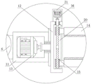
FIG. 2 is an enlarged view of part A of the structure of FIG. 1;
FIG. 3 is an enlarged view of the portion B of the structure of FIG. 1;
FIG. 4 is a sectional view of the connection structure of the ring-shaped groove and the positioning post;
fig. 5 is a top sectional view of the connection structure of the top mechanical arm and the adjusting member of the present invention.
In the figure: 1. a circuit rail; 2. adjusting the mounting plate; 3. a support box; 4. a servo motor; 5. rotating the rod; 6. a top mechanical arm; 7. a bottom mechanical arm; 8. an adjustment member; 801. a support pillar; 802. a hollow connecting block; 9. a first hydraulic cylinder; 10. a second hydraulic cylinder; 11. installing a pipe; 12. a mounting seat; 13. a stepping motor; 14. a clamping block; 15. a threaded rod; 16. a micro motor; 17. a heat dissipation port; 18. a dustproof breathable net; 19. an annular groove; 20. adjusting the sliding chute; 21. a positioning frame; 22. a reinforcing plate; 23. and a positioning column.
Detailed Description
The technical solutions in the embodiments of the present invention will be described clearly and completely with reference to the accompanying drawings in the embodiments of the present invention, and it is obvious that the described embodiments are only some embodiments of the present invention, not all embodiments. Based on the embodiments in the present invention, all other embodiments obtained by a person skilled in the art without creative work belong to the protection scope of the present invention.
Referring to fig. 1-5, a manipulator for demoulding and taking an injection molding part comprises a circuit guide rail 1, wherein the bottom of the circuit guide rail 1 is fixedly connected with an adjusting and mounting plate 2, the bottom of the adjusting and mounting plate 2 is fixedly connected with a support box 3, the inside of the support box 3 is fixedly connected with a servo motor 4, an output shaft of the servo motor 4 is fixedly connected with a rotating rod 5 through a coupler, the bottom of the rotating rod 5 penetrates through and is rotatably connected to the bottom of the support box 3, the bottom of the support box 3 is rotatably connected with a reinforcing plate 22, the bottom of the rotating rod 5 is fixedly connected with the top of the reinforcing plate 22, the bottom of the reinforcing plate 22 is fixedly connected with a top mechanical arm 6, the bottom of the top mechanical arm 6 is hinged with a bottom mechanical arm 7, and the middle part of the top mechanical arm 6 is hinged with an adjusting part 8;
the bottom of the reinforcing plate 22 is hinged with a first hydraulic cylinder 9, an output shaft of the first hydraulic cylinder 9 is hinged with the right side of the adjusting part 8, the left side of the adjusting part 8 is hinged with a second hydraulic cylinder 10, an output rod of the second hydraulic cylinder 10 is hinged with the left side of the bottom mechanical arm 7, the right end of the bottom mechanical arm 7 is fixedly connected with an installation pipe 11, the right side of the installation pipe 11 is rotatably connected with an installation seat 12, the inside of the installation pipe 11 is fixedly connected with a stepping motor 13, the output end of the stepping motor 13 is fixedly connected with the left side of the installation seat 12, the right side of the installation seat 12 is slidably connected with two clamping blocks 14, the middle parts of the two clamping blocks 14 are in threaded connection with an integrally formed threaded rod 15, the top of the installation seat 12 is fixedly connected with a micro motor 16, and the output end of the micro motor 16 is fixedly connected with the threaded rod 15 through a coupler;
in this embodiment, through operation servo motor 4, can drive reinforcing plate 22 by dwang 5, and then drive top arm 6 and bottom arm 7, make the arm can carry out rotation angle regulation, the middle part of top arm 6 articulates there is regulating part 8, first pneumatic cylinder 9 cooperation second pneumatic cylinder 10, utilize lever principle to control the angle of bottom arm 7, device angle regulation ability has further been promoted, step motor 13 operation can drive mount pad 12 and rotate, the grip block 14 that makes 12 right sides of mount pad installation can be stabilized rotating, the angle regulation ability of device has further been strengthened, make the device reach multi-direction and adjust, it is relatively better to get the material effect, manual work cooperation operation needs are lower, the cost of labor has been reduced.
Furthermore, the left side and the right side of the supporting box 3 are both provided with heat dissipation ports 17, and the interiors of the two heat dissipation ports 17 are both fixedly connected with dustproof breathable nets 18;
in this embodiment, through all having seted up thermovent 17 in the left and right sides of supporting box 3, can be to servo motor 4 after the operation, the heat that produces is got rid of the heat dissipation, and dustproof ventilative net 18 plays dustproof effect when, can dispel the heat, has increased the durability of device.
Furthermore, the top of the reinforcing plate 22 is rotatably connected with two positioning columns 23, the bottom of the adjusting and mounting plate 2 is provided with an annular groove 19, and the tops of the two positioning columns 23 extend and are connected to the inside of the annular groove 19 in a sliding manner;
in this embodiment, two positioning columns 23 are rotatably connected to the top of the reinforcing plate 22, and the annular groove 19 is formed in the bottom of the adjusting and mounting plate 2, and when the reinforcing plate 22 rotates, the two positioning columns 23 can move in the annular groove 19, so that the two positioning columns 23 can support the reinforcing plate 22, and the stability of the operation of the device is improved.
Further, the adjusting part 8 comprises two supporting columns 801 and a hollow connecting block 802, the hollow connecting block 802 is sleeved outside the top mechanical arm 6, one sides of the two supporting columns 801 opposite to each other are respectively rotatably connected with the front side and the back side of the top mechanical arm 6, and the sides of the two supporting columns 801 opposite to each other are fixedly connected with the inner side of the hollow connecting block 802;
in this embodiment, include two support columns 801 and a hollow connecting block 802 through setting up regulating part 8, two support columns 801 all rotate with top arm 6 and are connected to can play the supporting effect to hollow connecting block 802, make first pneumatic cylinder 9 and second pneumatic cylinder 10 when the operation promotes, hollow connecting block 802 can be the lever, carries out angle modulation to bottom arm 7, makes 7 angle modulation of bottom arm comparatively stable and high-efficient.
Furthermore, an adjusting sliding groove 20 is formed in the right side of the mounting seat 12, the left sides of the two clamping blocks 14 are connected to the inside of the adjusting sliding groove 20 in a sliding manner, a threaded rod 15 is rotatably connected to the inside of the adjusting sliding groove 20, and the top of the threaded rod 15 penetrates through the adjusting sliding groove 20 and is rotatably connected to the top of the mounting seat 12;
in this embodiment, through having seted up regulation spout 20 on the right side of mount pad 12, regulation spout 20 can play the location effect to two grip blocks 14 and a threaded rod 15, makes threaded rod 15 rotate comparatively stably, and threaded rod 15 is when two grip blocks 14 of drive are close to each other or keep away from, and regulation spout 20 can carry on spacingly to two grip blocks 14, makes two grip blocks 14 displacements comparatively stable, has increased the practicality of device.
Further, a positioning frame 21 is fixedly mounted at the top of the mounting seat 12, and the micro motor 16 is fixedly connected to the inner side of the positioning frame 21;
in this embodiment, the positioning frame 21 is fixedly mounted on the top of the mounting base 12, so that the micro motor 16 can be supported, the operation of the device is stable, and the stability of the device is improved.
The utility model discloses servo motor 4's model that uses can be SGMGV-09ADC6C, and step motor 13 all can be H5045 with micro motor 16's model, and the model of first pneumatic cylinder 9 and second pneumatic cylinder 10 all can be DY-24300, and it is provided with rather than supporting control switch, and control switch's mounted position can select according to the in-service use needs.
The working principle is as follows: the adjusting and mounting plate 2 is arranged at the bottom of the circuit guide rail 1, so that the circuit guide rail 1 can drive the adjusting and mounting plate 2 to displace, the supporting box 3 is arranged at the bottom of the adjusting and mounting plate 2 and can support the servo motor 4, after the servo motor 4 operates, the reinforcing plate 22 can be driven by the rotating rod 5 to further drive the top mechanical arm 6 and the bottom mechanical arm 7, so that the mechanical arms can rotate to adjust the angle, the middle part of the top mechanical arm 6 is hinged with an adjusting part 8, the first hydraulic cylinder 9 is matched with the second hydraulic cylinder 10 to control the angle of the bottom mechanical arm 7 by utilizing the lever principle, the angle adjusting capability of the device is further improved, the right side of the bottom mechanical arm 7 is fixedly connected with a mounting pipe 11, a stepping motor 13 is arranged in the mounting pipe 11, the stepping motor 13 operates to drive a mounting seat 12 to rotate, so that a clamping block 14 arranged at the right side of the mounting seat 12 can stably rotate, the angle modulation ability of device has further been strengthened, at last by micro motor 16 operation, can drive threaded rod 15, make two grip blocks 14 be close to each other or keep away from, carry out the efficient centre gripping to the injection molding, finally make the device reach and to adjust in many directions, it is relatively better to get the material effect, the manual fit operation needs are lower, the cost of labor has been reduced, common manipulator has been solved, can not be good enough to direction and angle modulation ability, need manual fit, work efficiency is low, the problem that working cost is high.
It is noted that, herein, relational terms such as first and second, and the like may be used solely to distinguish one entity or action from another entity or action without necessarily requiring or implying any actual such relationship or order between such entities or actions. Also, the terms "comprises," "comprising," or any other variation thereof, are intended to cover a non-exclusive inclusion, such that a process, method, article, or apparatus that comprises a list of elements does not include only those elements but may include other elements not expressly listed or inherent to such process, method, article, or apparatus. Without further limitation, an element defined by the phrase "comprising an … …" does not exclude the presence of other identical elements in a process, method, article, or apparatus that comprises the element.
Although embodiments of the present invention have been shown and described, it will be appreciated by those skilled in the art that changes, modifications, substitutions and alterations can be made in these embodiments without departing from the principles and spirit of the invention, the scope of which is defined in the appended claims and their equivalents.
Claims (6)
1. The utility model provides a manipulator is used to material is got in injection molding drawing of patterns, includes circuit guide rail (1), its characterized in that: the bottom of the circuit guide rail (1) is fixedly connected with an adjusting mounting plate (2), the bottom of the adjusting mounting plate (2) is fixedly connected with a support box (3), the inside of the support box (3) is fixedly connected with a servo motor (4), an output shaft of the servo motor (4) is fixedly connected with a rotating rod (5) through a coupler, the bottom of the rotating rod (5) penetrates through and is rotatably connected to the bottom of the support box (3), the bottom of the support box (3) is rotatably connected with a reinforcing plate (22), the bottom of the rotating rod (5) is fixedly connected with the top of the reinforcing plate (22), the bottom of the reinforcing plate (22) is fixedly connected with a top mechanical arm (6), the bottom of the top mechanical arm (6) is hinged with a bottom mechanical arm (7), and the middle of the top mechanical arm (6) is hinged with an adjusting part (8);
the bottom of the reinforcing plate (22) is hinged with a first hydraulic cylinder (9), an output shaft of the first hydraulic cylinder (9) is hinged with the right side of the adjusting part (8), the left side of the adjusting part (8) is hinged with a second hydraulic cylinder (10), an output rod of the second hydraulic cylinder (10) is hinged with the left side of the bottom mechanical arm (7), the right end of the bottom mechanical arm (7) is fixedly connected with an installation pipe (11), the right side of the installation pipe (11) is rotatably connected with an installation seat (12), the inside of the installation pipe (11) is fixedly connected with a stepping motor (13), the output end of the stepping motor (13) is fixedly connected with the left side of the installation seat (12), the right side of the installation seat (12) is slidably connected with two clamping blocks (14), and the middle threads of the two clamping blocks (14) are connected with an integrally formed threaded rod (15), the top fixedly connected with micro motor (16) of mount pad (12), micro motor's (16) output passes through shaft coupling and threaded rod (15) fixed connection.
2. The manipulator for demolding and taking the injection molded part as claimed in claim 1, wherein: the left side and the right side of the supporting box (3) are both provided with heat dissipation ports (17), and the inside of each heat dissipation port (17) is fixedly connected with a dustproof breathable net (18).
3. The manipulator for demolding and taking the injection molded part as claimed in claim 1, wherein: the top of reinforcing plate (22) is rotated and is connected with two reference columns (23), ring channel (19) have been seted up to the bottom of adjusting mounting panel (2), two the top of reference column (23) extends and sliding connection to the inside of ring channel (19).
4. The manipulator for demolding and taking the injection molded part as claimed in claim 1, wherein: adjusting part (8) include two support columns (801) and a hollow connecting block (802), the outside of top arm (6) is located to hollow connecting block (802) cover, two one side that support column (801) is relative rotates with the back with the front of top arm (6) respectively and is connected, two one side that support column (801) carried on the back mutually all with the inboard fixed connection of hollow connecting block (802).
5. The manipulator for demolding and taking the injection molded part as claimed in claim 1, wherein: adjusting chute (20), two have been seted up on the right side of mount pad (12) the equal sliding connection in the inside of adjusting chute (20) in left side of grip block (14), the internal rotation of adjusting chute (20) is connected with threaded rod (15), the top of threaded rod (15) is run through adjusting chute (20) and is rotated and be connected to the top of mount pad (12).
6. The manipulator for demolding and taking the injection molded part as claimed in claim 1, wherein: the top fixed mounting of mount pad (12) has locating rack (21), micro motor (16) fixed connection is in the inboard of locating rack (21).
Priority Applications (1)
| Application Number | Priority Date | Filing Date | Title |
|---|---|---|---|
| CN202022708968.3U CN213830181U (en) | 2020-11-20 | 2020-11-20 | Manipulator for demoulding and taking injection molding |
Applications Claiming Priority (1)
| Application Number | Priority Date | Filing Date | Title |
|---|---|---|---|
| CN202022708968.3U CN213830181U (en) | 2020-11-20 | 2020-11-20 | Manipulator for demoulding and taking injection molding |
Publications (1)
| Publication Number | Publication Date |
|---|---|
| CN213830181U true CN213830181U (en) | 2021-07-30 |
Family
ID=77018447
Family Applications (1)
| Application Number | Title | Priority Date | Filing Date |
|---|---|---|---|
| CN202022708968.3U Expired - Fee Related CN213830181U (en) | 2020-11-20 | 2020-11-20 | Manipulator for demoulding and taking injection molding |
Country Status (1)
| Country | Link |
|---|---|
| CN (1) | CN213830181U (en) |
Cited By (2)
| Publication number | Priority date | Publication date | Assignee | Title |
|---|---|---|---|---|
| CN114834011A (en) * | 2022-04-22 | 2022-08-02 | 重庆新天包装材料有限公司 | Plastic drum demolding equipment |
| CN117681416A (en) * | 2023-12-06 | 2024-03-12 | 南通博旭科技有限公司 | Material taking equipment of plastic thermoforming machine |
-
2020
- 2020-11-20 CN CN202022708968.3U patent/CN213830181U/en not_active Expired - Fee Related
Cited By (2)
| Publication number | Priority date | Publication date | Assignee | Title |
|---|---|---|---|---|
| CN114834011A (en) * | 2022-04-22 | 2022-08-02 | 重庆新天包装材料有限公司 | Plastic drum demolding equipment |
| CN117681416A (en) * | 2023-12-06 | 2024-03-12 | 南通博旭科技有限公司 | Material taking equipment of plastic thermoforming machine |
Similar Documents
| Publication | Publication Date | Title |
|---|---|---|
| CN222681575U (en) | Injection molding device with batch processing function | |
| CN215359836U (en) | Positioning device for plastic suction mold | |
| CN214137032U (en) | Injection device of injection molding machine | |
| CN212860389U (en) | A precision plastic mold device | |
| CN221456498U (en) | Mold releasing frame structure of rubber forming machine | |
| CN214000440U (en) | High-efficient clamping jaw of injection molding machine | |
| CN216544227U (en) | Large-scale water horse high-efficient shedder | |
| CN214521670U (en) | Mould hoist device, injection moulding device | |
| CN112223693A (en) | High-efficiency gripper for injection molding machine | |
| CN218965995U (en) | Plastic product rapid prototyping mould | |
| CN220464608U (en) | Adjustable die connecting structure | |
| CN216914633U (en) | Bi-directional mould structure for double-shot molding | |
| CN217777584U (en) | Injection molding fixing piece of bottom shell for high-abrasion-resistance computer | |
| CN220464453U (en) | Telescopic sole mould | |
| CN222406970U (en) | Device for assisting injection molding machine in demolding injection products | |
| CN218365982U (en) | Automatic manipulator of flat vulcanizing machine | |
| CN223618181U (en) | Automobile battery pack left-right mounting nut thermoforming mold | |
| CN118927549A (en) | A positive and negative self-stackable injection molding frame | |
| CN214773519U (en) | Mold displacement control mechanism for vertical injection molding machine | |
| CN220372045U (en) | Extrusion die for door angle section bar | |
| CN221475859U (en) | Extrusion forming mechanism for co-extrusion wood-plastic floor production | |
| CN222060937U (en) | A disassembly and assembly mechanism for conducting mold base | |
| CN214773826U (en) | Injection mold of artificial flower holds in palm leaf working of plastics | |
| CN223618170U (en) | Large sliding block built-in inclined ejection demoulding mechanism for injection mould of storage box of automobile center console | |
| CN217704547U (en) | Silica gel injection mold |
Legal Events
| Date | Code | Title | Description |
|---|---|---|---|
| GR01 | Patent grant | ||
| GR01 | Patent grant | ||
| CF01 | Termination of patent right due to non-payment of annual fee | ||
| CF01 | Termination of patent right due to non-payment of annual fee |
Granted publication date: 20210730 |