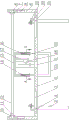
Panel cutting device for building engineering
Technical Field
The utility model belongs to the technical field of the panel cutting device, specifically speaking are panel cutting device for building engineering.
Background
The building materials are the general name of materials used in civil engineering and constructional engineering, the plates are flat rectangular building material plates made into standard sizes, the flat rectangular building material plates are applied to the building industry and are used for being used as components of walls, ceilings or floors, the cutting processing of the plates in the constructional engineering is generally realized by a cutting device, most of the existing building plate cutting devices have single functions, the dust-proof function is difficult to simultaneously realize, the chips generated by cutting are timely recovered and processed, the plates can be ensured to be always in a clamping state, the cutting effect is ensured, and the plates with different thicknesses and different sizes can be cut at different positions, so that the plate cutting device for the constructional engineering is required to be designed to solve the existing problems.
SUMMERY OF THE UTILITY MODEL
The utility model provides a panel cutting device for building engineering for solve the defect among the prior art.
The utility model discloses a following technical scheme realizes:
a plate cutting device for constructional engineering comprises an operation table, wherein four vertical rods are fixedly installed on a rectangular array on the bottom surface of the operation table, first chutes along the left and right directions are symmetrically formed in the left and right sides of the top surface of the operation table, first sliding blocks are connected in the first chutes in a sliding manner, plate clamping devices are fixedly installed on the top surfaces of the first sliding blocks, elongated through holes along the front and back directions are formed in the middle of the top surface of the operation table, first vertical plates are symmetrically and fixedly installed on the left and right sides of the operation table, vertical second chutes are formed in the opposite sides of the two first vertical plates, second sliding blocks are connected in the second chutes in a sliding manner, electric telescopic rods are fixedly installed on the bottom surfaces of the second sliding blocks, lower ends of fixing rods of the electric telescopic rods are fixedly connected with the bottom surfaces of the second chutes, guide rails along the front and back directions are fixedly installed on the opposite sides of the two second sliding blocks, electric sliding blocks are connected on the guide rails in a sliding manner, and transverse plates are arranged between the two electric sliding blocks, diaphragm side and the electronic slider side fixed connection who corresponds, diaphragm bottom surface fixed mounting cross section is the box that leaks hopper-shaped, box bottom surface and leading flank all open-ended, the recess is seted up to the box bottom surface, the cooperation barrel of pegging graft in the recess, the barrel leading flank, top surface and bottom surface all open-ended, the barrel cross section is leaking hopper-shaped, fixed mounting several spring between barrel top surface and the recess top surface, the side parallel and level that side and rectangular shape through-hole correspond about barrel rear portion inner wall, top surface fixed mounting second riser in the box, the fixed cutting machine in second riser side, the cutting piece position of cutting machine is corresponding with rectangular shape through-hole.
According to the plate cutting device for the building engineering, the clamping device comprises the mounting seat, the mounting seat is fixedly mounted on the top surface of the first sliding block, the top surface of the mounting seat penetrates through the screw rod, the screw rod is in threaded connection with the mounting seat, and the clamping block is fixedly mounted at the lower end of the screw rod.
According to the plate cutting device for the building engineering, the five-star handles are fixedly mounted at the upper ends of the screw rods.
According to the plate cutting device for the constructional engineering, the U-shaped collecting box is fixedly installed at the bottom surface of the operating platform corresponding to the elongated through hole, and the front side surface and the rear side surface of the U-shaped collecting box are communicated.
According to the plate cutting device for the building engineering, the bottom surface of the cylinder is flat and smooth.
The utility model has the advantages that: when the device works, a user horizontally places the device, controls the electric telescopic rod to extend, the electric telescopic rod pushes the second slide block to move upwards in the corresponding second chute, so that the transverse plate moves upwards until a board can be placed in a gap between the bottom surface of the barrel body and the top surface of the operating platform, then places a building board to be cut on the top surface of the operating platform, and ensures that the part of the board to be cut is positioned at the position of the long-strip-shaped through hole, the clamping device is convenient to clamp and fix the board by adjusting the position of the first slide block in the first chute, the electric telescopic rod is controlled to shorten, the electric telescopic rod pulls the second slide block to move downwards in the corresponding second chute, the transverse plate moves downwards at the moment, the bottom surface of the barrel body compresses the board, the spring is compressed, the cutting machine is started at the moment, the cutting piece of the cutting machine cuts the, the transverse plate drives the box body and the barrel body to move synchronously, the bottom surface of the barrel body is attached to the top surface of a plate, and the left side surface, the right side surface and the rear side surface of the box body and the barrel body are sealed, so that dust and debris cannot fall out of the box body and the barrel body in the process of cutting the box body and the barrel body from back to front, and the cross sections of the box body and the barrel body are funnel-shaped, as shown in figure 2, namely, the width between the left side surface and the right side surface of the box body and the width between the left side surface and the right side surface of the barrel body are both wide at the front part and narrow at the rear part, so that dust debris generated by cutting of the cutting machine can be; the utility model has the advantages of simple structure and easy operation, need not manual operation among the cutting process, the security of user's work has been improved, the device not only can cut different thickness and the not panel of equidimension, and can gather together the collection processing with the dust piece realization that the cutting produced in the cutting process, can reduce the harm that the dust is healthy to the user, and the piece that avoids the cutting to produce is gathered and is influenced going on smoothly of cutting process, and avoid cutting piece to the damage of panel and user's injury, because the barrel sticiss panel when the cutting, can also play the fixed action to panel, prevent the later stage at cutting process, closing device can't play effectual fixed to the panel about to cut off, ensure that the cutting effect meets the user's requirements.
Drawings
In order to more clearly illustrate the embodiments of the present invention or the technical solutions in the prior art, the drawings needed to be used in the description of the embodiments or the prior art will be briefly described below, and it is obvious that the drawings in the following description are some embodiments of the present invention, and for those skilled in the art, other drawings can be obtained according to these drawings without inventive labor.
Fig. 1 is a schematic structural diagram of the present invention; fig. 2 is an enlarged view of a cross-sectional view taken along line a-a of fig. 1.
Detailed Description
In order to make the objects, technical solutions and advantages of the embodiments of the present invention clearer, the embodiments of the present invention will be clearly and completely described below with reference to the accompanying drawings in the embodiments of the present invention, and it is obvious that the described embodiments are some, but not all, embodiments of the present invention. Based on the embodiments in the present invention, all other embodiments obtained by a person skilled in the art without creative efforts belong to the protection scope of the present invention.
A plate cutting device for building engineering comprises an operation table 1, four vertical rods 2 are fixedly installed on the bottom surface of the operation table 1 in a rectangular array mode, first chutes 3 along the left and right directions are symmetrically formed in the left and right sides of the top surface of the operation table 1, first sliding blocks 4 are connected in the first chutes 3 in a sliding mode, plate clamping devices are fixedly installed on the top surfaces of the first sliding blocks 4, long strip-shaped through holes 5 along the front and back directions are formed in the middle of the top surface of the operation table 1, first vertical plates 6 are symmetrically and fixedly installed on the left and right sides of the operation table 1, vertical second chutes 7 are formed in the opposite sides of the two first vertical plates 6, second sliding blocks 8 are connected in the second chutes 7 in a sliding mode, electric telescopic rods 9 are fixedly installed on the bottom surfaces of the second sliding blocks 8, the lower ends of fixing rods of the electric telescopic rods 9 are fixedly connected with the bottom surfaces of the second chutes 7, guide rails 10 along the front and back directions are fixedly installed on the opposite sides of the two second sliding blocks 8, equal sliding connection electric slider 11 on guide rail 10, set up diaphragm 12 between two electric slider 11, diaphragm 12 side and the electric slider 11 side fixed connection that corresponds, diaphragm 12 bottom surface fixed mounting cross section is the box 13 that leaks hopper-shaped, box 13 bottom surface and leading flank all open, recess 14 is seted up to box 13 bottom surface, peg graft cooperation barrel 15 in the recess 14, barrel 15 leading flank, top surface and bottom surface all open, barrel 15 cross section is leaking hopper-shaped, fixed mounting several spring 16 between barrel 15 top surface and the recess 14 top surface, the side parallel and level that the side corresponds with rectangular shape through-hole 5 about barrel 15 rear portion inner wall, top surface fixed mounting second riser 17 in the box 13, second riser 17 side fixed cutting machine 18, the cutting piece position of cutting machine 18 corresponds with rectangular shape through-hole 5. When the device works, a user horizontally places the device, controls the electric telescopic rod 9 to extend, the electric telescopic rod 9 pushes the second slide block 8 to move upwards in the corresponding second chute 7, so that the transverse plate 12 moves upwards until a gap between the bottom surface of the barrel body 15 and the top surface of the operating platform 1 can place a plate, then places a building plate to be cut on the top surface of the operating platform 1, ensures that the part of the plate to be cut is positioned at the elongated through hole 5, is convenient for the clamping device to clamp and fix the plate by adjusting the position of the first slide block 4 in the first chute 3, controls the electric telescopic rod 9 to shorten, the electric telescopic rod 9 pulls the second slide block 8 to move downwards in the corresponding second chute 7, the transverse plate 12 moves downwards at the moment, the bottom surface of the barrel body 15 compresses the plate, the spring 14 is compressed, the cutting machine 18 is started at the moment, and the cutting piece of the cutting machine 18 cuts the plate, the electric sliding block 11 is controlled to move forwards from back to back on the guide rail 10, the transverse plate 12 drives the box body 13 and the cylinder body 15 to move synchronously, the bottom surface of the cylinder body 15 is clung to the top surface of the plate, and the left side surface and the right side surface of the box body 13 and the cylinder body 15 are sealed, so that dust and scraps cannot fall out of the box body 13 and the cylinder body 15 in the process of cutting the box body 13 and the cylinder body 15 from back to front by the cutting machine 18, and as the cross sections of the box body 13 and the cylinder body 15 are funnel-shaped, as shown in fig. 2, namely, the width between the left side surface and the right side surface of the box body 13 and the cylinder body 15 is wide at the front part and narrow at the back part, the dust scraps produced by cutting by the cutting machine 18 can be gradually gathered towards the middle part of the cylinder body 15 in the process of moving the cylinder body 15 from back to front, and the gathered dust scraps can fall out downwards through the strip-shaped through hole 5, so that a user can conveniently collect and process in a centralized manner; the utility model has the advantages of simple structure and easy operation, need not manual operation among the cutting process, the security of user's work has been improved, the device not only can cut different thickness and the not panel of equidimension, and can gather together the collection processing with the dust piece realization that the cutting produced in the cutting process, can reduce the harm that the dust is healthy to the user, and the piece of avoiding cutting to produce is gathered and is influenced going on smoothly of cutting process, and avoid cutting piece to the damage of panel and user's injury, because barrel 15 sticiss panel when the cutting, can also play the fixed action to panel, prevent the later stage at cutting process, closing device can't play effectual fixed to the panel about to cut off, ensure that the cutting effect meets the user's requirement.
Specifically, as shown in the figures, the clamping device according to the present embodiment includes a mounting seat 19, the mounting seat 19 is fixedly mounted on the top surface of the first sliding block 4, the top surface of the mounting seat 19 penetrates through a screw rod 20, the screw rod 20 is in threaded connection with the mounting seat 19, and the clamping block 21 is fixedly mounted at the lower end of the screw rod 20. This design is guaranteed to place the panel that will need the cutting when the user behind 1 top surface of operation panel, according to the thickness of panel, through rotating screw rod 20, adjusts the height of pressing from both sides tight piece 21, makes to press from both sides tight piece 21 bottom surface and panel top surface and hug closely, ensures the stability of panel in the cutting process, guarantees that the cutting effect satisfies the user's requirement.
Specifically, as shown in the drawings, the upper end of the screw 20 in this embodiment is fixedly mounted with a five-star handle 22. This design guarantees through rotating five stars handle 22, and the realization that the user can be more relaxed is to the adjustment of clamping block 21 high position to the realization that can be more laborsaving is to the clamp of panel tightly with loosen, reduces user's working strength.
Further, as shown in the figure, a U-shaped collecting box 23 is fixedly installed on the bottom surface of the operating table 1 corresponding to the elongated through hole 5, and the front side surface and the rear side surface of the U-shaped collecting box 23 are through. This design is guaranteed the device and is cutting panel in-process, and the dust piece that falls down in the rectangular shape through-hole 5 can directly fall into the U type and collect box 23 in, and convenient to use person can not only alleviate the pollution to the environment to the clastic concentrated processing of dust, can also reduce the healthy harm of dust piece to the user.
Further, as shown in the drawings, the bottom surface of the cylinder 15 of the present embodiment is flat and smooth. This design guarantees when the device cuts panel, because the barrel 15 bottom surface compresses tightly panel and the relative panel of barrel 15 removes, consequently when the bottom surface of barrel 15 and panel contact levels and when smooth, ensures that the device can normally work.
Finally, it should be noted that: the above embodiments are only used to illustrate the technical solution of the present invention, and not to limit it; although the present invention has been described in detail with reference to the foregoing embodiments, it should be understood by those skilled in the art that: the technical solutions described in the foregoing embodiments may still be modified, or some technical features may be equivalently replaced; such modifications and substitutions do not depart from the spirit and scope of the present invention in its corresponding aspects.