CN213823033U - A ventilation device that realizes different ventilation states of both lungs - Google Patents

A ventilation device that realizes different ventilation states of both lungs Download PDF

Info

Publication number
CN213823033U
CN213823033U CN202020744068.1U CN202020744068U CN213823033U CN 213823033 U CN213823033 U CN 213823033U CN 202020744068 U CN202020744068 U CN 202020744068U CN 213823033 U CN213823033 U CN 213823033U
Authority
CN
China
Prior art keywords
ventilation
catheter
lumen
joint
lungs
Prior art date
Legal status (The legal status is an assumption and is not a legal conclusion. Google has not performed a legal analysis and makes no representation as to the accuracy of the status listed.)
Expired - Fee Related
Application number
CN202020744068.1U
Other languages
Chinese (zh)
Inventor
许仄平
顾连兵
王丽君
Current Assignee (The listed assignees may be inaccurate. Google has not performed a legal analysis and makes no representation or warranty as to the accuracy of the list.)
Jiangsu Cancer Hospital
Original Assignee
Jiangsu Cancer Hospital
Priority date (The priority date is an assumption and is not a legal conclusion. Google has not performed a legal analysis and makes no representation as to the accuracy of the date listed.)
Filing date
Publication date
Application filed by Jiangsu Cancer Hospital filed Critical Jiangsu Cancer Hospital
Priority to CN202020744068.1U priority Critical patent/CN213823033U/en
Application granted granted Critical
Publication of CN213823033U publication Critical patent/CN213823033U/en
Expired - Fee Related legal-status Critical Current
Anticipated expiration legal-status Critical

Links

Images

Landscapes

  • External Artificial Organs (AREA)

Abstract

本实用新型提供了实现两侧肺不同通气状态的通气装置,属于医疗器械技术领域,包括主管、三腔气管、接头、双腔气管插管、气囊和充气管,所述三腔气管一端与所述主管连接,另一端通过所述接头与所述双腔气管插管连接,所述双腔气管插管靠近所述接头一端的外侧设置有所述气囊,所述气囊连接有所述充气管,所述充气管用于实现所述气囊的充气或排气。本实用新型所述的通气装置以不同的潮气量对两肺进行控制通气,有效保证了手术的肺部能够保持呼吸状态,从而避免了术后肺部并发症的发生。

Figure 202020744068

The utility model provides a ventilation device for realizing different ventilation states of the lungs on both sides, belonging to the technical field of medical equipment, comprising a main pipe, a three-lumen trachea, a joint, a double-lumen tracheal intubation, an airbag and an inflation tube. The main pipe is connected, the other end is connected with the double-lumen endotracheal tube through the joint, the double-lumen endotracheal tube is provided with the airbag at the outer side of one end of the double-lumen endotracheal tube close to the joint, and the airbag is connected with the inflation tube, The inflation tube is used to inflate or deflate the airbag. The ventilation device of the utility model controls and ventilates the two lungs with different tidal volumes, which effectively ensures that the lungs in operation can maintain the breathing state, thereby avoiding the occurrence of postoperative pulmonary complications.

Figure 202020744068

Description

Ventilation device for realizing different ventilation states of two lungs
Technical Field
The utility model belongs to the technical field of medical instrument, especially, relate to a ventilation unit who realizes the different states of ventilating of both sides lung.
Background
At present, in thoracic surgery, a unilung ventilation technique is generally adopted, that is, a lung on a non-operation side is ventilated, and a lung on an operation side is not ventilated, so that the lung on the operation side is in a collapse state.
SUMMERY OF THE UTILITY MODEL
In view of this, the present invention aims to provide an airway device capable of reducing postoperative pulmonary complications and realizing different airway states of both lungs.
In order to achieve the above purpose, the technical scheme of the utility model is realized like this: the ventilation device for realizing different ventilation states of the lungs on two sides comprises a main pipe, a three-cavity trachea, a joint, a double-cavity trachea cannula, an air bag and an inflation pipe, wherein one end of the three-cavity trachea is connected with the main pipe, the other end of the three-cavity trachea is connected with the double-cavity trachea cannula through the joint, the air bag is arranged on the outer side, close to one end of the joint, of the double-cavity trachea cannula, the air bag is connected with the inflation pipe, and the inflation pipe is used for realizing inflation or exhaust of the air bag.
Furthermore, three chamber trachea include full air-permeable pipe, first operation pipe, second operation pipe, pressure limiting valve and relief pressure valve, the one end of full air-permeable pipe, first operation pipe and second operation pipe is merged into a pipe, simultaneously, the other end of full air-permeable pipe with the joint connection, the other end of first operation pipe and second operation pipe is merged into a pipe then with the joint connection, the pressure limiting valve sets up on the first operation pipe, the relief pressure valve sets up on the second operation pipe.
Furthermore, pressure gauges are respectively arranged on the pressure reducing valve and the pressure limiting valve.
Furthermore, the joint comprises a connecting block and two connecting through holes, wherein the two connecting through holes are arranged in the connecting block, one end of each connecting through hole is used for connecting the full-ventilation catheter, the other end of each connecting through hole is used for connecting the double-cavity tracheal cannula, one end of each connecting through hole is used for connecting the combined end of the first surgical catheter and the second surgical catheter, and the other end of each connecting through hole is used for connecting the double-cavity tracheal cannula.
Compared with the prior art, the ventilation device for realizing different ventilation states of the two lungs has the following advantages: breather control with the tidal volume of difference and ventilate to two lungs, the lung of having effectively guaranteed the operation can keep respiratory state to postoperative lung complication's emergence has been avoided.
Drawings
The accompanying drawings, which form a part hereof, are included to provide a further understanding of the invention, and are incorporated in and constitute a part of this specification, illustrate embodiments of the invention and together with the description serve to explain the invention without undue limitation. In the drawings:
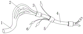
fig. 1 is a schematic structural view of an air breather according to an embodiment of the present invention;
fig. 2 is a schematic structural view of a three-cavity trachea according to an embodiment of the present invention;
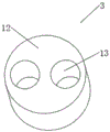
fig. 3 is a schematic structural diagram of a joint according to an embodiment of the present invention.
Description of reference numerals:
1. a main pipe; 2. a three-cavity air pipe; 3. a joint; 4. a double-cavity tracheal cannula; 5. an air bag; 6. an inflation tube; 7. a full-venting conduit; 8. a first surgical catheter; 9. a second surgical catheter; 10. a pressure limiting valve; 11. a pressure reducing valve; 12. connecting blocks; 13. and connecting the through holes.
Detailed Description
It should be noted that, in the present invention, the embodiments and features of the embodiments may be combined with each other without conflict.
In the description of the present invention, it is to be understood that the terms "center", "longitudinal", "lateral", "up", "down", "front", "back", "left", "right", "vertical", "horizontal", "top", "bottom", "inner", "outer", and the like, indicate orientations or positional relationships based on the orientations or positional relationships shown in the drawings, and are used merely for convenience of description and for simplicity of description, and do not indicate or imply that the device or element being referred to must have a particular orientation, be constructed and operated in a particular orientation, and therefore, should not be construed as limiting the present invention. Furthermore, the terms "first", "second", etc. are used for descriptive purposes only and are not to be construed as indicating or implying relative importance or implicitly indicating the number of technical features indicated. Thus, a feature defined as "first," "second," etc. may explicitly or implicitly include one or more of that feature. In the description of the present invention, "a plurality" means two or more unless otherwise specified.
In the description of the present invention, it is to be noted that, unless otherwise explicitly specified or limited, the terms "mounted," "connected," and "connected" are to be construed broadly, and may be, for example, fixedly connected, detachably connected, or integrally connected; can be mechanically or electrically connected; they may be connected directly or indirectly through intervening media, or they may be interconnected between two elements. The specific meaning of the above terms in the present invention can be understood by those of ordinary skill in the art through specific situations.
The present invention will be described in detail below with reference to the accompanying drawings in conjunction with embodiments.
As shown in fig. 1-3, the utility model discloses a realize different ventilation status's of both sides lung ventilation device, including being responsible for 1, three trachea 2, joint 3, two-chamber trachea cannula 4, gasbag 5 and gas tube 6, three trachea 2 one end of chamber with be responsible for 1 and connect, the other end passes through joint 3 with two-chamber trachea cannula 4 is connected, be responsible for 1 and keep away from the breathing machine is connected to three trachea 2's one end, and the breathing machine is prior art, two-chamber trachea cannula 4 is close to the outside that connects 3 one end is provided with gasbag 5, gasbag 5 be used for with ventilation device fixes the position at pharyngeal, gasbag 5 is connected with gas tube 6, gas tube 6 is used for realizing the inflation or the exhaust of gasbag 5.
The three-cavity trachea 2 comprises a full-ventilation catheter 7, a first surgical catheter 8, a second surgical catheter 9, a pressure limiting valve 10 and a pressure reducing valve 11, one end of the full-ventilation catheter 7, one end of the first surgical catheter 8 and one end of the second surgical catheter 9 are combined into one catheter, the other end of the full-ventilation catheter 7 is connected with the joint 3, the other end of the first surgical catheter 8 and the other end of the second surgical catheter 9 are combined into one catheter and then connected with the joint 3, the pressure reducing valve 11 is arranged on the second surgical catheter 9, the pressure of gas fed by a breathing machine can be reduced through the pressure reducing valve 11, the pressure fed into the second surgical catheter 9 on the surgical side is kept constant, the pressure can be adjusted according to actual conditions, and gas higher than a pressure set value cannot enter into the lungs on the surgical side, for example: the pressure reducing valve 11 is adjusted to only pass gas with 10cmH2O pressure, the respirator gives gas with 30cmH2O pressure, the operation side lung only has gas with 10cmH2O pressure, ventilation with small tidal volume is carried out, the operation of a doctor is facilitated, and the other side lung is mechanically ventilated with normal gas with 30cmH2O pressure. The pressure limiting valve 10 is arranged on the first operation catheter 8, after the operation is finished, the operation side lung needs to keep more alveoli open at the end of expiration, the occurrence of pulmonary atelectasis after the operation is reduced, the pressure in the operation side lung can be maintained at a certain value through the pressure limiting valve 10, and the gas smaller than the pressure value cannot be discharged, so that the alveoli at the operation side keep an open state with at least certain pressure, for example: the pressure limiting valve 10 is adjusted to maintain gas with the pressure of 10cmH2O, so that the operation side lung always has gas with the pressure of 10cmH2O, the just collapsed alveoli of the operation side lung are kept expanded, and the occurrence of postoperative pulmonary complications is reduced; pressure gauges are respectively arranged on the pressure reducing valve 11 and the pressure limiting valve 10, so that an operator can conveniently and visually read the set pressure value of the pressure reducing valve 11 or the pressure limiting valve 10.
The joint 3 comprises a connecting block 12 and two connecting through holes 13, wherein the connecting through holes 13 are arranged in the connecting block 12, one end of one of the connecting through holes 13 is used for connecting the full-ventilation catheter 7, the other end of the connecting through hole is used for connecting the double-cavity tracheal cannula 4, the other end of the other connecting through hole 13 is used for connecting the combined end of the first surgical catheter 8 and the second surgical catheter 9, and the other end of the connecting through hole 13 is used for connecting the double-cavity tracheal cannula 4.
[F1] Firstly, a double-cavity tracheal cannula 4 is placed into a trachea of a patient through a mouth of the patient, the trachea cannula is fixed by inflating an air bag 5, a main tube 1 is connected with a breathing machine, a pressure limiting valve 10 is closed, a pressure reducing valve 11 is opened, a pressure value required by an operation is set, the operation can be carried out, after the operation is finished, the pressure reducing valve 11 is closed, the pressure limiting valve 10 is set, and the pressure limiting valve 10 is opened.
The above description is only a preferred embodiment of the present invention, and should not be taken as limiting the invention, and any modifications, equivalent replacements, improvements, etc. made within the spirit and principle of the present invention should be included in the protection scope of the present invention.
Claims (4)

1.实现两侧肺不同通气状态的通气装置,其特征在于:包括主管(1)、三腔气管(2)、接头(3)、双腔气管插管(4)、气囊(5)和充气管(6),所述三腔气管(2)一端与所述主管(1)连接,另一端通过所述接头(3)与所述双腔气管插管(4)连接,所述双腔气管插管(4)靠近所述接头(3)一端的外侧设置有所述气囊(5),所述气囊(5)连接有所述充气管(6),所述充气管(6)用于实现所述气囊(5)的充气或排气。1. the ventilation device that realizes the different ventilation states of the lungs on both sides, it is characterized in that: comprise main pipe (1), three-lumen trachea (2), joint (3), double-lumen tracheal intubation (4), air bag (5) and inflation A tube (6), one end of the three-lumen trachea (2) is connected to the main pipe (1), and the other end is connected to the double-lumen tracheal intubation tube (4) through the joint (3), the double-lumen trachea The airbag (5) is provided on the outer side of the cannula (4) close to one end of the joint (3), the airbag (5) is connected with the inflation tube (6), and the inflation tube (6) is used to realize Inflation or deflation of the airbag (5). 2.根据权利要求1所述的实现两侧肺不同通气状态的通气装置,其特征在于:所述三腔气管(2)包括全通气导管(7)、第一手术导管(8)、第二手术导管(9)、限压阀(10)和减压阀(11),所述全通气导管(7)、第一手术导管(8)和第二手术导管(9)的一端合并为一根导管,同时,所述全通气导管(7)的另一端与所述接头(3)连接,所述第一手术导管(8)和第二手术导管(9)的另一端合并为一根导管然后在与所述接头(3)连接,所述限压阀(10)设置在所述第一手术导管(8)上,所述减压阀(11)设置在所述第二手术导管(9)上。2. The ventilation device for realizing different ventilation states of the lungs on both sides according to claim 1, wherein the three-lumen trachea (2) comprises a full ventilation catheter (7), a first surgical catheter (8), a second A surgical catheter (9), a pressure limiting valve (10) and a pressure reducing valve (11), one end of the full ventilation catheter (7), the first surgical catheter (8) and the second surgical catheter (9) are combined into one At the same time, the other end of the full ventilation catheter (7) is connected with the joint (3), the other ends of the first surgical catheter (8) and the second surgical catheter (9) are merged into one catheter and then In connection with the joint (3), the pressure limiting valve (10) is provided on the first surgical catheter (8), and the pressure reducing valve (11) is provided on the second surgical catheter (9) superior. 3.根据权利要求2所述的实现两侧肺不同通气状态的通气装置,其特征在于:所述减压阀(11)和限压阀(10)上分别设置有压力表。3 . The ventilation device for realizing different ventilation states of the lungs on both sides according to claim 2 , wherein the pressure reducing valve ( 11 ) and the pressure limiting valve ( 10 ) are respectively provided with pressure gauges. 4 . 4.根据权利要求2所述的实现两侧肺不同通气状态的通气装置,其特征在于:所述接头(3)包括连接块(12)和连接通孔(13),所述连接块(12)内设置有两个所述连接通孔(13),其中一个所述连接通孔(13),一端用来连接所述全通气导管(7),另一端用来连接所述双腔气管插管(4),另一个所述连接通孔(13),一端用来连接所述第一手术导管(8)和第二手术导管(9)的合并端,另一端用来连接所述双腔气管插管(4)。4. The ventilation device for realizing different ventilation states of the lungs on both sides according to claim 2, wherein the joint (3) comprises a connecting block (12) and a connecting through hole (13), and the connecting block (12) ) is provided with two connecting through holes (13), one of the connecting through holes (13), one end is used to connect the full ventilation catheter (7), the other end is used to connect the double lumen endotracheal tube A pipe (4), another said connecting through hole (13), one end is used to connect the combined end of the first surgical catheter (8) and the second surgical catheter (9), and the other end is used to connect the double lumen Endotracheal tube (4).
CN202020744068.1U 2020-05-08 2020-05-08 A ventilation device that realizes different ventilation states of both lungs Expired - Fee Related CN213823033U (en)

Priority Applications (1)

Application Number Priority Date Filing Date Title
CN202020744068.1U CN213823033U (en) 2020-05-08 2020-05-08 A ventilation device that realizes different ventilation states of both lungs

Applications Claiming Priority (1)

Application Number Priority Date Filing Date Title
CN202020744068.1U CN213823033U (en) 2020-05-08 2020-05-08 A ventilation device that realizes different ventilation states of both lungs

Publications (1)

Publication Number Publication Date
CN213823033U true CN213823033U (en) 2021-07-30

Family

ID=76986921

Family Applications (1)

Application Number Title Priority Date Filing Date
CN202020744068.1U Expired - Fee Related CN213823033U (en) 2020-05-08 2020-05-08 A ventilation device that realizes different ventilation states of both lungs

Country Status (1)

Country Link
CN (1) CN213823033U (en)

Cited By (1)

* Cited by examiner, † Cited by third party
Publication number Priority date Publication date Assignee Title
CN114849003A (en) * 2022-06-13 2022-08-05 四川大学华西医院 Artificial airway air bag pressure adjusting system for respirator and using method thereof

Cited By (2)

* Cited by examiner, † Cited by third party
Publication number Priority date Publication date Assignee Title
CN114849003A (en) * 2022-06-13 2022-08-05 四川大学华西医院 Artificial airway air bag pressure adjusting system for respirator and using method thereof
CN114849003B (en) * 2022-06-13 2023-12-01 四川大学华西医院 Artificial airway air bag pressure regulating system for breathing machine and application method thereof

Similar Documents

Publication Publication Date Title
US9242058B2 (en) Tracheal tube positioning devices and methods
US20130047993A1 (en) Tracheal tube having a flange with a variable volume
CN110237390A (en) artificial airway
CN106964047A (en) A kind of single-lumen bronchial tube of single, double lung switching ventilation
CN102068742A (en) Single-cavity multi-bag trachea catheter
CN201978294U (en) Single-chamber trachea catheter possessing functions of phlegm suction and single or double lung ventilation
CN104524678A (en) Lung isolation catheter
CN201558393U (en) Single-cavity multi-bag tracheal tube
CN112642037A (en) Double-cavity bronchial catheter
CN212383060U (en) Trachea cannula for airway operation
CN101474447B (en) Multifunctional universal joint of trachea cannula
CN221600950U (en) Disposable trachea cannula capable of being compressed and inflated manually
CN212547889U (en) Improved single-cavity bronchial catheter
CN110448775B (en) Lung isolation ventilation tube
CN216061577U (en) Ventilation device for realizing different ventilation states of two lungs
CN219700741U (en) Tracheal cannula
CN217311503U (en) A high-frequency jet ventilation tracheal tube
CN210078522U (en) Formula of can letting out trachea shutoff type trachea cannula
CN205549179U (en) Double -cavity bronchial cannula
CN213131409U (en) Inflatable tracheal catheter
CN205569473U (en) Novel double -balloon bronchus disabler
CN201299879Y (en) Trachea and bronchus dual-type catheter
CN215194753U (en) Steel wire thread inflatable telescopic double-cavity bronchial catheter
CN221579312U (en) Double-cavity tracheal catheter
CN213252281U (en) A single lumen double balloon bronchial catheter

Legal Events

Date Code Title Description
GR01 Patent grant
GR01 Patent grant
CF01 Termination of patent right due to non-payment of annual fee

Granted publication date: 20210730

CF01 Termination of patent right due to non-payment of annual fee