Dredging device for hydraulic engineering
Technical Field
The utility model relates to a hydraulic engineering technical field specifically is a desilting device for hydraulic engineering.
Background
Hydraulic engineering is an engineering built for controlling and allocating surface water and underground water in the nature to achieve the purpose of removing harm and benefiting, is also called water engineering, water is a valuable resource essential for human production and life, but the naturally existing state of the water does not completely meet the needs of human beings, and only when the hydraulic engineering is built, water flow can be controlled to prevent flood disasters, and water quantity regulation and distribution are performed to meet the needs of people's life and production on water resources. Hydraulic engineering needs to build various types of hydraulic buildings such as dams, dikes, spillways, water gates, water inlets, channels, transition troughs, rafts, fishways and the like so as to achieve the aims.
Some existing dredging facilities are low in efficiency, a large amount of manpower and material resources are needed, some foreign matters which are large in size and hard can exist in some river channels, some water plants can exist, the cleaning is troublesome, and sometimes the dredging facilities can be blocked and damaged, so that the dredging device for the hydraulic engineering is provided.
SUMMERY OF THE UTILITY MODEL
An object of the utility model is to provide a sediment removal device for hydraulic engineering to solve the problem that proposes in the above-mentioned background art.
In order to achieve the above object, the utility model provides a following technical scheme: a dredging device for hydraulic engineering comprises a ship body, wherein a sludge storage tank, a sludge treatment tank and a support frame are respectively arranged at the top of the ship body, one end of the support frame is fixedly connected to the top of the ship body, the other end of the support frame is fixedly connected with a lifting hydraulic rod, the bottom end of the lifting hydraulic rod is fixedly connected with a water inlet pipeline, the bottom end of the water inlet pipeline is fixedly connected with a sludge absorption pipe and a stirring device, one end of the water inlet pipeline is sealed, the other end of the water inlet pipeline is fixedly connected with one end of a sludge suction hose, the other end of the sludge suction hose is fixedly connected to the top of a sludge pump, the bottom end of the sludge pump is fixedly connected with one end of a water inlet pipe, the other end of the water inlet pipe is fixedly connected to one side of the sludge treatment tank, a second hydraulic push rod is arranged at the, the top of silt processing box is provided with first hydraulic push rod.
Preferably, the inside of silt treatment case is provided with silt treatment chamber and river water collection room, silt treatment chamber and river water collection room are separated by the filter, the silt treatment chamber is located the top of river water collection room.
Preferably, one side of silt processing box is provided with row's silt mouth, it is connected with the silt processing box rotation through the hinge to arrange the silt mouth.
Preferably, the output end of the first hydraulic push rod is fixedly connected with a pressing plate, and the pressing plate is located inside the sludge treatment tank.
Preferably, the middle part of the support frame is fixedly connected with a triangular support rod.
Preferably, a motor is arranged in the stirring device, and the output end of the motor is fixedly connected with a cutter head.
Compared with the prior art, the utility model provides a sediment removal device for hydraulic engineering possesses following beneficial effect:
1. the utility model is provided with the stirring device, the cutter disc which can rotate at high speed is arranged below the stirring device, so that the sludge can be scattered to be loosened, the waterweeds and hard foreign bodies can be crushed, the sludge absorption effect is better, the efficiency is higher, and the blockage and damage to the utility model can not be caused; by arranging the lifting mechanism, the dredging operation of underwater environments with different depths can be well competent in different environments, and the operation is more convenient and effective;
2. the utility model discloses a set up the silt processing case, be provided with the silt processing chamber above the silt processing case, the below is river water collecting chamber, be separated by the filter between silt processing chamber and the river water collecting chamber, silt after the processing is pushed into the mud storage chamber through the push rod, and river water gets into river water collecting chamber through filtering, is connected with the outlet pipe on the lateral wall of river water collecting chamber, silt is separated with the river water, the silt is retrieved in the mud storage chamber, the river water then flows back in the river course, the burden of boats and ships has been lightened on the one hand; on the other hand, the water storage capacity of the river channel is ensured;
3. the utility model has the advantages that by arranging the first hydraulic push rod and the second hydraulic push rod, when muddy water enters the sludge treatment chamber, the first hydraulic push rod compresses the sludge, redundant water enters the river water collection chamber through the filter plate, after the compression is finished, the first hydraulic push rod is restored, and the second hydraulic push rod pushes the sludge into the sludge storage box, so that the method is fast and convenient, and the manpower is effectively saved;
the part that does not relate to in the device all is the same with prior art or can adopt prior art to realize, the utility model has the advantages of being scientific and reasonable in structure, convenience safe in utilization provides very big help for people.
Drawings
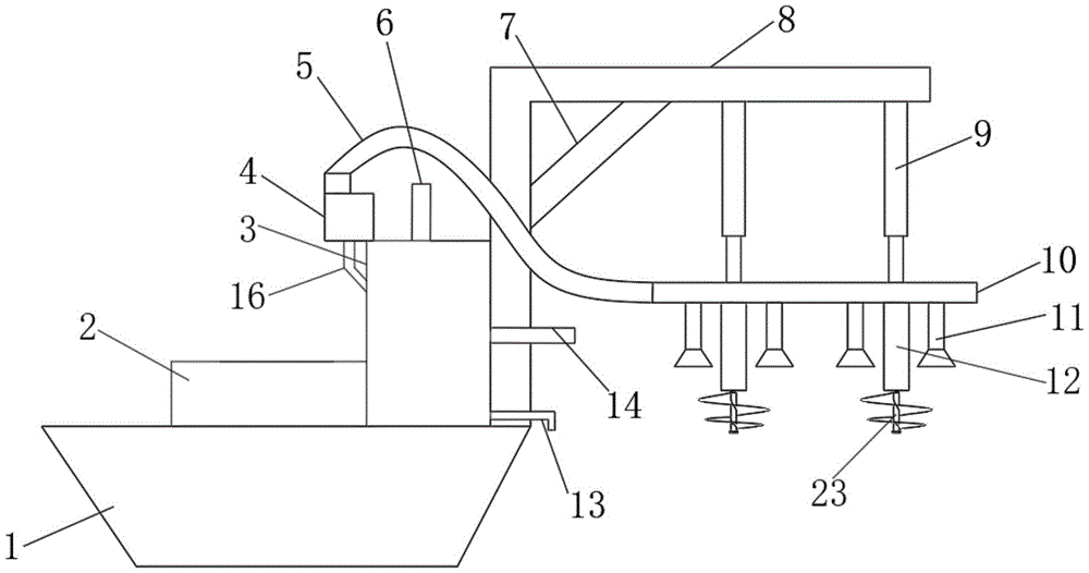
FIG. 1 is a schematic front view of a dredging device for hydraulic engineering;
FIG. 2 is a schematic cross-sectional view of a dredging device for hydraulic engineering;
fig. 3 is a schematic structural diagram of a sludge treatment tank in the dredging device for hydraulic engineering.
Description of the reference numerals
The sludge treatment device comprises a ship body 1, a sludge storage tank 2, a sludge treatment tank 3, a sludge pump 4, a sludge suction hose 5, a first hydraulic push rod 6, a triangular support rod 7, a support frame 8, a lifting hydraulic rod 9, a water inlet pipeline 10, a sludge absorption pipe 11, a stirring device 12, a water outlet pipe 13, a second hydraulic push rod 14, a motor 15, a water inlet pipe 16, a hinge 17, a sludge discharge port 18, a filter plate 19, a pressing plate 20, a sludge treatment chamber 21, a river water collection chamber 22 and a cutter head 23.
Detailed Description
The following detailed description of the embodiments of the present invention will be made with reference to the accompanying drawings. It is to be understood that the description of the embodiments herein is for purposes of illustration and explanation only and is not intended to limit the invention.
In the description of the present invention, it should be noted that the terms "upper", "lower", "inner", "outer", "front end", "rear end", "both ends", "one end", "the other end", and the like indicate orientations or positional relationships based on the orientations or positional relationships shown in the drawings, and are only for convenience of description and simplification of description, but do not indicate or imply that the device or element to be referred must have a specific orientation, be constructed in a specific orientation, and be operated, and thus, should not be construed as limiting the present invention. Furthermore, the terms "first" and "second" are used for descriptive purposes only and are not to be construed as indicating or implying relative importance.
In the description of the present invention, it is to be noted that, unless otherwise explicitly specified or limited, the terms "mounted," "disposed," "connected," and the like are to be construed broadly, and for example, "connected" may be a fixed connection, a detachable connection, or an integral connection; can be mechanically or electrically connected; they may be connected directly or indirectly through intervening media, or they may be interconnected between two elements. The specific meaning of the above terms in the present invention can be understood in specific cases to those skilled in the art.
Referring to fig. 1-3, the present invention provides a technical solution: a dredging device for hydraulic engineering comprises a ship body 1, wherein a sludge storage tank 2, a sludge treatment tank 3 and a support frame 8 are respectively arranged at the top of the ship body 1, one end of the support frame 8 is fixedly connected at the top of the ship body 1, the other end of the support frame 8 is fixedly connected with a lifting hydraulic rod 9, the bottom end of the lifting hydraulic rod 9 is fixedly connected with a water inlet pipeline 10, the bottom end of the water inlet pipeline 10 is fixedly connected with a sludge absorption pipe 11 and a stirring device 12, one end of the water inlet pipeline 10 is sealed, the other end of the water inlet pipeline 10 is fixedly connected with one end of a sludge absorption hose 5, the other end of the sludge absorption hose 5 is fixedly connected at the top of a sludge pump 4, the bottom end of the sludge pump 4 is fixedly connected with one end of a water inlet pipe 16, the other end of the water inlet pipe 16 is fixedly connected at one side of the sludge treatment tank 3, a second hydraulic push rod 14 is arranged at the other side of the sludge treatment tank 3, and a water outlet pipe 13 is arranged below the second hydraulic push rod 14, the top of the sludge treatment tank 3 is provided with a first hydraulic push rod 6; by arranging the stirring device, the cutter disc 23 which can rotate at high speed is arranged below the stirring device, so that the sludge can be scattered to be loosened, aquatic plants and hard foreign matters can be crushed, the sludge absorption effect is better, the efficiency is higher, and the blockage and damage to the utility model can not be caused; through setting up elevating system, to different environment, the desilting operation of the environment under water of the different degree of depth can all be competent well, and is more convenient, effective.
Preferably, the inside of the sludge treatment tank 3 is provided with a sludge treatment chamber 21 and a river water collection chamber 22, the sludge treatment chamber 21 and the river water collection chamber 22 are separated by a filter plate 19, and the sludge treatment chamber 21 is positioned above the river water collection chamber 22; through setting up silt process chamber 21 and river and collecting room 22, during silt after the processing pushed into storage mud tank 2 through second hydraulic push rod 14 push rod, and the river then gets into the river through filter 19 and collects the room, silt and river separation, and silt are retrieved in storage mud tank 2, and the river then flows back in the river course, has lightened the burden of boats and ships on the one hand, and on the other hand has guaranteed the water storage capacity in river course.
Preferably, one side of the sludge treatment tank 3 is provided with a sludge discharge port 18, and the sludge discharge port 18 is rotatably connected with the sludge treatment tank 3 through a hinge 17; by arranging the sludge discharge port 18, sludge in the sludge treatment tank 3 can be discharged into the sludge storage tank, so that the sludge treatment speed is effectively increased.
Preferably, the output end of the first hydraulic push rod 6 is fixedly connected with a pressure plate 20, and the pressure plate 20 is positioned inside the sludge treatment tank 3.
Preferably, the middle part of the supporting frame 8 is fixedly connected with a triangular supporting rod 7; through setting up tripod bracing piece 7, can effectively guarantee the stability of support frame 8.
Preferably, a motor 15 is arranged in the stirring device 12, and a cutter disc 23 is fixedly connected to the output end of the motor 15; through setting up motor 15, drive the blade disc 23 motion of agitating unit bottom, can break up silt and make it not hard up, can also smash pasture and water and hard foreign matter, it is better to absorb the silt effect, makes efficiency become higher.
The utility model discloses a theory of operation and use flow: when the device is used, a ship is placed in a river needing dredging, the height of the lifting hydraulic rod 9 is adjusted, the water inlet pipeline 10 is placed at a proper position under water, the motor 15 and the silt pump 4 are turned on, the device starts to work, silt is scattered, the silt is sucked into the water inlet pipeline 10 through the silt absorption pipe 11 and is conveyed into the silt processing chamber 21 through the silt suction hose 5 and the water inlet pipe 16, at the moment, the first hydraulic push rod 6 starts to work, the first hydraulic push rod 6 pushes the pressing plate 20 to press the silt in the silt processing chamber 21, redundant river water enters the river water collecting chamber 22 through the filtering plate 19 and then flows back into the river through the water outlet pipe 13, the silt which cannot pass through the filtering plate 19 is remained in the silt processing chamber 21, when the first hydraulic push rod 6 rises to the top, the second hydraulic push rod 14 starts to work, the silt in the silt processing chamber 21 is pushed to be pushed into the silt storage tank 2 through the silt discharge port 18, the first hydraulic push rod 6 and the second hydraulic push rod 14 move alternately, after the dredging operation is completed, the motor 15 and the sediment pump 4 are turned off, and the water inlet pipeline 10 is pulled back to the original position to be fixed through the lifting hydraulic rod 9 so as to be used next time.
The preferred embodiments of the present invention have been described in detail above, but the present invention is not limited thereto. In the technical idea scope of the present invention, it can be right to the technical solution of the present invention perform multiple simple modifications, including each technical feature combined in any other suitable manner, these simple modifications and combinations should be regarded as the disclosed content of the present invention, and all belong to the protection scope of the present invention.