CN213795592U - Polishing equipment for processing and producing diamond saw blade - Google Patents
Polishing equipment for processing and producing diamond saw blade Download PDFInfo
- Publication number
- CN213795592U CN213795592U CN202022216854.7U CN202022216854U CN213795592U CN 213795592 U CN213795592 U CN 213795592U CN 202022216854 U CN202022216854 U CN 202022216854U CN 213795592 U CN213795592 U CN 213795592U
- Authority
- CN
- China
- Prior art keywords
- motor
- screw rod
- lead screw
- transmission shaft
- length direction
- Prior art date
- Legal status (The legal status is an assumption and is not a legal conclusion. Google has not performed a legal analysis and makes no representation as to the accuracy of the status listed.)
- Active
Links
Images
Abstract
The utility model discloses a polishing equipment of processing production diamond saw bit relates to the diamond saw bit field of polishing, which comprises a bod, the organism includes desktop board and supporting leg, the desktop board upper end is equipped with the casing, the desktop board upper end is equipped with grinding wheel grinding subassembly and feeding mechanism, the grinding wheel grinding subassembly includes first transmission shaft, secondary drive axle, cylindric link, emery wheel piece and driven pulleys, feeding mechanism includes first bar groove, first lead screw slide, displacement seat, second bar groove, second lead screw slide, support frame, disc cylinder mounting bracket and location cylinder, desktop board position below is equipped with the auxiliary stand, the auxiliary stand upper end is equipped with motor and collection dirt casing. The polishing equipment realizes the built-in processing of the diamond saw blade, realizes the mechanized feeding and discharging of the diamond saw blade, and realizes the flexible regulation and control of the position of the saw blade to be subjected to grinding processing.
Description
Technical Field
The utility model relates to a diamond saw bit field of polishing, concretely relates to equipment of polishing of processing production diamond saw bit.
Background
Diamond saw bit need process the operation of polishing in process of production, and current equipment of polishing can produce a large amount of dust particles when realizing diamond saw bit abrasive machining, and the dust particle if not clear away in time, can cause very big harm for operating personnel health. When the diamond saw blade is used for grinding, the diamond saw blade is usually held by hand or fastened in position, and when the diamond saw blade is held by hand or fastened in position, the diamond saw blade not only can increase the manual burden, but also can cause a great deal of inconvenience in the grinding process of the saw blade, so that the grinding processing efficiency is reduced. Therefore, a new solution is now needed.
Disclosure of Invention
In order to solve the problem, the utility model discloses an equipment of polishing of processing production diamond saw bit, this equipment of polishing realize the built-in processing of diamond saw bit, play the environmental protection effect of removing dust for equipment operation environment is effectively ensured. The diamond saw blade mechanical feeding and discharging is realized, the flexible regulation and control of the position of the saw blade to be subjected to abrasive machining are realized, and the saw blade abrasive machining efficiency is greatly improved while the saw blade abrasive machining is facilitated.
In order to achieve the above purpose, the utility model provides a following technical scheme: the utility model provides a grinding equipment of processing production diamond saw blade, includes the organism, the organism includes the even vertical supporting leg that is equipped with of desktop board and desktop board lower extreme, the desktop board upper end is equipped with the casing, desktop board length direction one side upper end is equipped with emery wheel grinding subassembly, opposite side upper end is equipped with feeding mechanism, emery wheel grinding subassembly includes first transmission shaft that desktop board upper end medial side and be equipped with along its width direction, first transmission shaft divide equally along its length direction position both sides respectively equipped with second transmission shaft, divide equally between first transmission shaft and the second transmission shaft respectively equipped with cylindric link, second transmission shaft correspond first transmission shaft position other side outside and equally divide respectively overlap grinding wheel and the driven pulleys that first transmission shaft length direction medial side outside overlaps, feeding mechanism includes desktop board upper end and correspond the grinding wheel position equally divide respectively open first bar groove, the supporting leg that is equipped with, First lead screw and first lead screw slide that all is equipped with in the first bar recess, the equal fixed displacement seat that is equipped with in first lead screw slide upper end, displacement seat upper end and equally divide along its length direction the second bar recess that do not open, the second lead screw and the second lead screw slide that all are equipped with in the second bar recess, the equal vertical fixed support frame that is equipped with in second lead screw slide length direction both sides upper end, disc cylinder mounting bracket and the disc cylinder mounting bracket that is equipped with along the equal fixed location cylinder that is equipped with in the corresponding end wall middle part of second lead screw slide length direction along the corresponding end wall top side of second lead screw slide length direction, desktop board position below just is located fixed and is equipped with the auxiliary stand between the supporting leg, the auxiliary stand upper end is equipped with first motor and collection dirt casing.
As an improvement of the utility model, the casing is designed to be opened at the other side end corresponding to the position of the grinding wheel grinding component without a terminal plate, the bore of the inner end of the cylindrical connecting frame is larger than the diameter of the cross section of the first transmission shaft and the second transmission shaft, the outer end walls at both sides of the length direction of the cylindrical connecting frame are equally provided with connecting screw holes with equal radian, connecting screws are evenly screwed in the connecting screw holes, the first strip-shaped groove is arranged along the length direction of the table panel, the first screw rod is movably arranged to penetrate through the first screw rod sliding seat, a first screw rod transmission component is respectively arranged between the inner end wall at the movable penetrating part of the first screw rod sliding seat and the outer part of the first screw rod, the end part of the other side end corresponding to the position of the grinding wheel grinding component is movably penetrated through the inner end wall of the first strip-shaped groove to extend, and the end part of the extending end of the first screw rod sliding seat is externally connected with a second motor, the displacement seat and the second lead screw sliding seat are arranged along the width direction of the table top plate, the second lead screws are movably penetrated through the second lead screw sliding seat, a second lead screw transmission assembly is arranged between the inner end wall of the movably penetrated position of the second lead screw sliding seat and the outer part of the second lead screw, one end part of the second lead screw in the length direction movably penetrates through the inner end wall of the second strip-shaped groove and stretches out, and the end part of the stretching end of the second lead screw is externally connected with a third motor. The first screw rod transmission assembly and the second screw rod transmission assembly are both designed by adopting the existing screw rod transmission principle technology.
As an improvement of the utility model, second lead screw slide length direction one side is equipped with the fourth motor just the activity of fourth motor output shaft runs through rather than the support frame bottom portion setting that is close to mutually, the outside and corresponding disc cylinder mounting bracket position cover of fourth motor output shaft has drive gear, and the equal division of isoplanar degree has the transmission tooth's socket on the disc cylinder mounting bracket outside circumference end wall that is located directly over the transmission gear position, the outside teeth of a cogwheel of drive gear with the transmission tooth's socket meshes the transmission each other, the flexible end tip of location cylinder is the fixed locating piece that is equipped with all. The first motor, the second motor, the third motor and the fourth motor are all rotating motors.
As an improvement of the utility model, a driving belt wheel is sleeved outside the output shaft of the first motor, a belt is sleeved between the driving belt wheel and the outside of the driven belt wheel and movably penetrates through the tabletop plate, a dust collecting cover body is respectively arranged at the top end in the shell and corresponding to the position of the grinding wheel piece, the dust collecting shell body is arranged beside the side of the position of the first motor, a ventilation shell is arranged on the outer end wall of one side of the dust collection shell corresponding to the position of the first motor, the output shaft of the first motor extends into the ventilation shell, fan blades are uniformly arranged in the ventilation shell and outside the output shaft of the first motor, a ventilation hole is formed between the ventilation shell and the dust collection shell, just correspond in the dust collecting housing the ventilation hole position is equipped with the screen panel, the dust collecting housing all through the pipeline with the dust collecting housing is linked together, the ventilation casing corresponds it has the air exit to open on the first motor position one side end wall.
Compared with the prior art, the utility model has the advantages of as follows: this equipment of polishing realizes the built-in processing of diamond saw bit, plays environmental protection dust removal effect for equipment operation environment obtains effective guarantee. The feeding mechanism can realize the mechanized feeding and discharging of the saw blade and the flexible regulation and control of the position of the saw blade, and greatly improves the grinding efficiency while facilitating the grinding processing of the saw blade.
Drawings
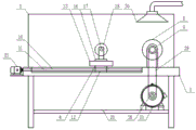
FIG. 1 is a schematic view of the overall structure of a polishing device for processing and producing diamond saw blades according to the present invention;
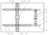
figure 2 is a schematic view of the upper end of the table top;
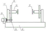
fig. 3 is a schematic structural view of the upper end of the second screw slide seat;
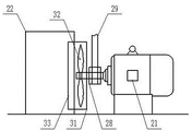
FIG. 4 is a schematic view of the first motor transmission structure;
list of reference numerals: 1. a table top plate; 2. a housing; 3. grinding the component by using a grinding wheel; 4. a feeding mechanism; 5. a first drive shaft; 6. a second drive shaft; 7. a cylindrical connecting frame; 8. a grinding wheel sheet; 9. a driven pulley; 10. a first bar-shaped groove; 11. a first lead screw; 12. a first lead screw slide; 13. a displacement seat; 14. a second strip-shaped groove; 15. a second lead screw; 16. a second lead screw slide seat; 17. a support frame; 18. a disc-shaped cylinder mounting frame; 19. positioning the air cylinder; 20. an auxiliary support; 21. a first motor; 22. a dust collecting housing; 23. a second motor; 24. a third motor; 25. a fourth motor; 26. a transmission gear; 27. positioning blocks; 28. a driving pulley; 29. a belt; 30. a dust collection cover body; 31. a ventilated casing; 32. a fan blade; 33. a mesh enclosure.
Detailed Description
Example 1: referring to fig. 1, 2, 3 and 4, the grinding apparatus for manufacturing diamond saw blades according to the present invention is described, which comprises a machine body including a table top plate 1 and supporting legs vertically fixed at the lower end of the table top plate 1, a housing 2 is disposed at the upper end of the table top plate 1, a grinding wheel grinding assembly 3 is disposed at the upper end of one side of the table top plate 1 in the length direction, a feeding mechanism 4 is disposed at the upper end of the other side of the table top plate 1, the grinding wheel grinding assembly 3 includes a first transmission shaft 5 disposed at the middle side of the upper end of the table top plate 1 in the width direction, a second transmission shaft 6 disposed at the first transmission shaft 5 along the two sides of the length direction, a cylindrical connecting frame 7 disposed between the first transmission shaft 5 and the second transmission shaft 6, a grinding wheel 8 disposed on the second transmission shaft 6 corresponding to the outer portion of the other side of the position of the first transmission shaft 5, and a driven pulley 9 disposed at the middle side of the first transmission shaft 5 in the length direction, the feeding mechanism 4 comprises a first strip-shaped groove 10 which is respectively arranged at the upper end of the table board 1 and corresponds to the position of the grinding wheel 8, a first screw rod 11 and a first screw rod slide seat 12 which are respectively arranged in the first strip-shaped groove 10, a displacement seat 13 which is fixedly arranged at the upper end of the first screw rod slide seat 12, a second strip-shaped groove 14 which is respectively arranged at the upper end of the displacement seat 13 along the length direction, a second screw rod 15 and a second screw rod slide seat 16 which are respectively arranged in the second strip-shaped groove 14, a supporting frame 17 which is vertically and fixedly arranged at the upper end of two sides of the length direction of the second screw rod slide seat 16, a disc-shaped air cylinder mounting frame 18 which is movably arranged at the top side of the end wall corresponding to the length direction of the second screw rod slide seat 16 along the supporting frame 17, and a positioning air cylinder 19 which is fixedly arranged at the middle part of the disc-shaped air cylinder mounting frame 18 along the length direction of the second screw rod slide seat 16, and auxiliary supports 20 which are fixedly arranged below the position of the table board 1 and are arranged between the supporting legs, the upper end of the auxiliary bracket 20 is provided with a first motor 21 and a dust collecting housing 22.
Example 2: referring to fig. 1 and 2, it is right now that the utility model provides a pair of the equipment of polishing of processing production diamond saw blade explains, casing 2 corresponds 3 positions of grinding wheel grinding subassembly another side opening does not have the end plate design, 7 inner bores of cylindric link are all greater than 6 cross section diameters of first transmission shaft 5, second transmission shaft, it has the connection screw to equally divide respectively to wait radian evenly to open on the 7 length direction both sides outer end wall of cylindric link, just it has the connecting screw to equally divide in the connection screw to equally divide respectively to twist, first bar groove 10 is all followed 1 length direction of desktop board is seted up, 11 equal activities of first lead screw are run through first lead screw slide 12 sets up, 12 activities of first lead screw slide run through department inner end wall with it does not be equipped with first lead screw transmission subassembly to equally divide between 11 outsides of first lead screw, first lead screw 11 corresponds the equal activities of grinding wheel grinding subassembly 3 positions another side tip is run through in first bar groove 10 The end wall extends out, the end portion of the extending end of the end wall is externally connected with a second motor 23, the displacement seat 13 and the second lead screw sliding seat 16 are arranged along the width direction of the table board 1, the second lead screw 15 movably penetrates through the second lead screw sliding seat 16, a second lead screw transmission assembly is arranged between the inner end wall of the movably penetrating position of the second lead screw sliding seat 16 and the outside of the second lead screw 15, one end portion of the second lead screw 15 in the length direction movably penetrates through the inner end wall of the second strip-shaped groove 14 to extend out, and the end portion of the extending end of the second lead screw is externally connected with a third motor 24.
Example 3: referring to fig. 1 and 3, it is right now that the utility model provides a pair of the equipment of polishing of processing production diamond saw blade explains, 16 length direction one side of second lead screw slide is equipped with fourth motor 25 just fourth motor 25 output shaft activity runs through rather than the setting of 17 bottom portions of support frame that are close to mutually, the outside and corresponding disc cylinder mounting bracket 18 position cover of fourth motor 25 output shaft has drive gear 26, and the equal division of isoplanar has the transmission tooth's socket on the disc cylinder mounting bracket 18 outside circumference end wall directly over being located drive gear 26 position, the outside teeth of a cogwheel of drive gear 26 with the transmission tooth's socket meshes the transmission each other, 19 flexible end tip of location cylinder is all fixed and is equipped with locating piece 27.
Example 4: referring to fig. 1, 2 and 4, the grinding device for processing and producing diamond saw blades according to the present invention is now described, wherein a driving pulley 28 is sleeved outside an output shaft of the first motor 21, a belt 29 is sleeved between the driving pulley 28 and the driven pulley 9, the belt 29 movably penetrates the table top plate 1, a dust collecting cover 30 is respectively disposed at the top end of the housing 2 corresponding to the position of the grinding wheel 8, the dust collecting housing 22 is disposed beside the position of the first motor 21, a ventilation housing 31 is disposed on the outer end wall of the dust collecting housing 22 corresponding to the position of the first motor 21, the output shaft of the first motor 21 extends into the ventilation housing 31, fan blades 32 are uniformly disposed inside the ventilation housing 31 and outside the output shaft of the first motor 21, and a ventilation hole is formed between the ventilation housing 31 and the dust collecting housing 22, just correspond in the collection dirt casing 22 the ventilation hole position is equipped with screen panel 33, the collection dirt cover body 30 all through the pipeline with collection dirt casing 22 is linked together, ventilation casing 31 corresponds it has the air exit to open on the end wall of first motor 21 position one side.
The utility model discloses can also form new implementation mode with embodiment 1 with at least one in embodiment 2, 3, 4 the technical characterstic.
The working principle is as follows: the diamond saw blade to be ground drives the positioning block to move through the positioning cylinder, and clamping and fastening of the position can be achieved. The first motor can drive the grinding wheel to rotate through the driving belt wheel, the belt, the driven belt wheel, the first transmission shaft and the second transmission shaft, and the diamond saw blade grinding machining is realized through the rotation of the grinding wheel. The first motor can drive the first transmission shaft to rotate through the driving belt wheel, the belt and the driven belt wheel, the first transmission shaft can be fixedly connected with the second transmission shaft through the cylindrical connecting frame and the connecting screw, the second transmission shaft can be driven to rotate through the rotation of the first transmission shaft, and the grinding wheel is driven to rotate through the second transmission shaft. The second motor can drive the first lead screw to rotate, the first lead screw can drive the first lead screw sliding seat to reciprocate along the length direction of the first lead screw through the first lead screw transmission assembly in the rotating process of the first lead screw, and the diamond saw blade to be ground can be regulated and controlled once in position by the movement of the first lead screw sliding seat. The third motor can drive the second lead screw to rotate, the second lead screw can drive the second lead screw sliding seat to reciprocate along the length direction of the second lead screw through the second lead screw transmission assembly in the rotating process of the second lead screw, and the secondary regulation and control of the position of the diamond saw blade to be ground can be realized through the movement of the second lead screw sliding seat. The fourth motor can drive the disc-shaped cylinder mounting rack to rotate through the transmission gear and the transmission tooth socket, so that the diamond saw blade to be ground can be driven to rotate. A large amount of dust particles can be generated during grinding of the diamond saw blade, the fan blades can be driven to rotate by operation of the first motor, and air flow guiding effect can be achieved by rotation of the fan blades. The rotation of flabellum can make the inside negative pressure that produces of dust collecting housing, and the produced granule of diamond saw blade processing can be through leading-in dust collecting housing of pipeline, and the rethread screen cover realizes filtering. The rotation of flabellum can make the air blow to first motor, can also realize first motor heat dissipation.
The technical means disclosed by the scheme of the present invention is not limited to the technical means disclosed by the above embodiments, but also includes the technical scheme formed by the arbitrary combination of the above technical features. It should be noted that, for those skilled in the art, without departing from the principle of the present invention, several improvements and modifications can be made, and these improvements and modifications are also considered as the protection scope of the present invention.
Claims (4)
1. The utility model provides a grinding equipment of processing production diamond saw blade, includes the organism, the organism includes desktop board (1) and the even vertical supporting leg that is equipped with of desktop board (1) lower extreme, its characterized in that, desktop board (1) upper end is equipped with casing (2), desktop board (1) length direction one side upper end is equipped with emery wheel grinding subassembly (3), opposite side upper end is equipped with feeding mechanism (4), emery wheel grinding subassembly (3) include in desktop board (1) upper end the side just along first transmission shaft (5) that its width direction was equipped with, first transmission shaft (5) are equallyd divide other second transmission shaft (6) that do not are equipped with, first transmission shaft (5) and second transmission shaft (6) between equallyd divide between do not be equipped with between cylindric link (7), second transmission shaft (6) correspond outside and equally divide in first transmission shaft (5) position other side of other transmission shaft (5) of other cover have emery wheel piece (8) and first transmission shaft (5) length direction Driven pulley (9) that the outside of side was overlapped, feeding mechanism (4) include desktop board (1) upper end just corresponds first bar groove (10) that do not open are equallyd divide to emery wheel (8) position, first lead screw (11) and first lead screw slide (12) all be equipped with in first bar groove (10), first lead screw slide (12) upper end all fixed be equipped with displacement seat (13), displacement seat (13) upper end just equally divide along its length direction second bar groove (14) that do not open, all be equipped with in second bar groove (14) second lead screw (15) and second lead screw slide (16), the equal vertical support frame (17) that are equipped with in second lead screw slide (16) length direction both sides upper end, disc cylinder mounting bracket (18) and disc cylinder (18) that the corresponding end slide top side of length direction of support frame (17) all movable be equipped with along second lead screw (16) length direction The middle of the end is fixedly provided with a positioning cylinder (19), an auxiliary support (20) is fixedly arranged below the desktop plate (1) and between the supporting legs, and the upper end of the auxiliary support (20) is provided with a first motor (21) and a dust collecting shell (22).
2. The grinding apparatus for manufacturing a diamond saw blade according to claim 1, wherein: the shell (2) is designed to have an opening at the other side end corresponding to the grinding wheel grinding assembly (3), the inner end calibers of the cylindrical connecting frame (7) are larger than the diameters of the cross sections of the first transmission shaft (5) and the second transmission shaft (6), the outer end walls at two sides of the length direction of the cylindrical connecting frame (7) are respectively and uniformly provided with connecting screw holes with equal radian, connecting screws are respectively screwed into the connecting screw holes, the first strip-shaped groove (10) is respectively arranged along the length direction of the table top plate (1), the first screw rod (11) movably penetrates through the first screw rod sliding seat (12), a first screw rod transmission assembly is respectively arranged between the inner end wall at the movable penetrating part of the first screw rod sliding seat (12) and the outer part of the first screw rod (11), the end part of the first screw rod (11) at the other side end corresponding to the grinding wheel grinding assembly (3) movably penetrates through the inner end wall of the first strip-shaped groove (10) to extend out, and the end part of the extending end of the second screw rod is externally connected with a second motor (23), the displacement seat (13) and the second screw rod sliding seat (16) are arranged along the width direction of the table top plate (1), the second screw rod (15) is movably penetrated through the second screw rod sliding seat (16), a second screw rod transmission assembly is respectively arranged between the inner end wall of the movable penetrating position of the second screw rod sliding seat (16) and the outside of the second screw rod (15), one end part of the equal length direction of the second screw rod (15) is movably penetrated through the inner end wall of the second bar-shaped groove (14) to extend out, and the end part of the extending end of the second screw rod is respectively externally connected with a third motor (24).
3. The grinding apparatus for manufacturing a diamond saw blade according to claim 2, wherein: second lead screw slide (16) length direction one side is equipped with fourth motor (25) just fourth motor (25) output shaft activity runs through rather than support frame (17) bottom portion setting that is close to mutually, the outside and corresponding disc cylinder mounting bracket (18) position cover of fourth motor (25) output shaft has drive gear (26), and the equal division of equal radian has the transmission tooth's socket on disc cylinder mounting bracket (18) outside circumference end wall that is located directly over drive gear (26) position, the outside teeth of a cogwheel of drive gear (26) with the transmission tooth's socket meshes the transmission each other, location cylinder (19) flexible end tip is all fixed and is equipped with locating piece (27).
4. The grinding apparatus for manufacturing a diamond saw blade according to claim 1, wherein: the outer cover of first motor (21) output shaft has driving pulley (28), driving pulley (28) with the cover has belt (29) between driven pulley (9) the outside, belt (29) activity runs through desktop board (1) sets up, top just corresponds in casing (2) the emery wheel piece (8) position is equallyd divide and is equipped with dust collecting cover body (30) respectively, dust collecting shell (22) are located by first motor (21) position side, dust collecting shell (22) correspond be equipped with ventilation casing (31) on the outer end wall of first motor (21) position one side, first motor (21) output shaft stretches into in ventilation casing (31), ventilation casing (31) just be located first motor (21) output shaft outside evenly is equipped with flabellum (32), ventilation casing (31) with it has the ventilation hole to open between dust collecting casing (22), just correspond in the collection dirt casing (22) the vent hole position is equipped with screen panel (33), the collection dirt cover body (30) all through the pipeline with collection dirt casing (22) are linked together, ventilation casing (31) correspond it has the air exit to open on the end wall of first motor (21) position one side.
Priority Applications (1)
| Application Number | Priority Date | Filing Date | Title |
|---|---|---|---|
| CN202022216854.7U CN213795592U (en) | 2020-10-09 | 2020-10-09 | Polishing equipment for processing and producing diamond saw blade |
Applications Claiming Priority (1)
| Application Number | Priority Date | Filing Date | Title |
|---|---|---|---|
| CN202022216854.7U CN213795592U (en) | 2020-10-09 | 2020-10-09 | Polishing equipment for processing and producing diamond saw blade |
Publications (1)
| Publication Number | Publication Date |
|---|---|
| CN213795592U true CN213795592U (en) | 2021-07-27 |
Family
ID=76956736
Family Applications (1)
| Application Number | Title | Priority Date | Filing Date |
|---|---|---|---|
| CN202022216854.7U Active CN213795592U (en) | 2020-10-09 | 2020-10-09 | Polishing equipment for processing and producing diamond saw blade |
Country Status (1)
| Country | Link |
|---|---|
| CN (1) | CN213795592U (en) |
Cited By (1)
| Publication number | Priority date | Publication date | Assignee | Title |
|---|---|---|---|---|
| CN113681448A (en) * | 2021-08-18 | 2021-11-23 | 无锡钱桥纺机设备有限公司 | Groove drum shaft polisher |
-
2020
- 2020-10-09 CN CN202022216854.7U patent/CN213795592U/en active Active
Cited By (1)
| Publication number | Priority date | Publication date | Assignee | Title |
|---|---|---|---|---|
| CN113681448A (en) * | 2021-08-18 | 2021-11-23 | 无锡钱桥纺机设备有限公司 | Groove drum shaft polisher |
Similar Documents
| Publication | Publication Date | Title |
|---|---|---|
| CN211063075U (en) | Electric power cabinet convenient to heat dissipation | |
| CN213795592U (en) | Polishing equipment for processing and producing diamond saw blade | |
| CN108747677A (en) | A kind of roughing deburring equipment of steering motor shell | |
| CN111673461A (en) | Machining is with all-in-one of polishing that punches a hole | |
| CN208913632U (en) | A kind of hardware knob drilling equipment | |
| CN210908371U (en) | Processing production device for high-voltage bus | |
| CN208853851U (en) | Cutting equipment is used in a kind of pressure pump clack box processing of oil fracturing vehicle | |
| CN213470584U (en) | End face deburring device for machining pulley | |
| CN112975402A (en) | Drilling polishing machine for manufacturing and processing motor parts | |
| CN212471736U (en) | Automatic change cutting machine | |
| CN215942378U (en) | Device is repaired to notebook computer shell deckle edge | |
| CN213353039U (en) | Rutile production is with cutting all-in-one for drilling | |
| CN213615918U (en) | Environment-friendly grinding machine | |
| CN211388038U (en) | Self-lubricating slide graphite grinds flat machinery | |
| CN212471733U (en) | Simple cutting equipment | |
| CN210307034U (en) | Safe and efficient grinding machine | |
| CN213615811U (en) | Explosion-proof grinding machine | |
| CN208528219U (en) | Dust-extraction unit is used in a kind of cutting of electromechanical component | |
| CN214869540U (en) | Automobile parts equipment of polishing | |
| CN112059819B (en) | Grinder convenient to adjust | |
| CN220347931U (en) | Cylindrical centerless grinding device | |
| CN212470701U (en) | Cleaning device for cutting machine workbench | |
| CN213615622U (en) | Grinding wheel machine work platform that polishes | |
| CN112355822A (en) | Processing equipment for brake block | |
| CN213469883U (en) | Wire cutting machine for part machining |
Legal Events
| Date | Code | Title | Description |
|---|---|---|---|
| GR01 | Patent grant | ||
| GR01 | Patent grant |