CN213771799U - Deoiling, desanding and dewatering device for light oil sludge in oil field - Google Patents
Deoiling, desanding and dewatering device for light oil sludge in oil field Download PDFInfo
- Publication number
- CN213771799U CN213771799U CN202022621342.9U CN202022621342U CN213771799U CN 213771799 U CN213771799 U CN 213771799U CN 202022621342 U CN202022621342 U CN 202022621342U CN 213771799 U CN213771799 U CN 213771799U
- Authority
- CN
- China
- Prior art keywords
- tank
- oil
- pipeline
- sludge
- port
- Prior art date
- Legal status (The legal status is an assumption and is not a legal conclusion. Google has not performed a legal analysis and makes no representation as to the accuracy of the status listed.)
- Active
Links
Images


Abstract
The utility model relates to a deoiling, desanding and dewatering device for light oil sludge in oil field, belonging to a separating device, which comprises a cleaning tank, an oil storage tank, a stirring tank, a cyclone desander, an air-floated oil removal tank, a high-efficiency coagulator and a serial spiral sludge dewatering machine; the upper portion of washing jar be equipped with the inlet connection of raw materials import, bottom discharge gate through pipeline A and whirl sand remover, the bottom discharge gate of whirl sand remover passes through pipeline B and is connected with the inlet of air supporting deoiling jar, the oil-out on air supporting deoiling jar upper portion and oil storage tank tube coupling, the discharge gate of bottom passes through pipeline C and is connected with the inlet of agitator tank, the discharge gate of agitator tank has connected gradually high-efficient coagulation ware and cluster spiral shell sludge dewaterer through pipeline D. The device is suitable for separating light sludge, the raw materials are sequentially washed, desanded and deoiled after being added with medicine, and then enter the high-efficiency coagulator for mud-water separation, and the generated mud cakes are discharged; the energy consumption is low; the automation degree is high; the maintenance cost is low.
Description
Technical Field
The utility model belongs to separator especially involves an oil field light dirty fatlute deoiling, degritting and dewatering device.
Background
At present, most oil fields in China enter the middle and later stages of development, the average water content in produced liquid is 70-80%, and the average water content is even up to 90%. Because the oil extraction sewage is a multiphase system which is formed after oil-water separation and integrates suspended solid, oil and dissolved substances, the sewage has higher oil deposit harmfulness, stronger corrosiveness and certain scaling property. Therefore, the oil production wastewater must be treated before reinjection. The reasons for the formation of impurities in oilfield wastewater are as follows:
1) sulfides are commonly present in produced water of an oil field, and a series of complex problems of serious corrosion, scaling, sulfate reducing bacteria SRB propagation, difficult treatment and the like are caused. The sulfide in the oil field produced water is mainly S2-、SO4 2-Is present in the form of, in addition, a small amount of S2O3 2-. Sulfides are mainly derived from the following four aspects: one is present in the formation, brought to the surface as oil is produced; secondly, the production is carried out in the production process; thirdly, sulfide generated by putrefactive degradation of organic matters; fourthly, SO in water is reduced by Sulfate Reducing Bacteria (SRB)4 2-Reduction to S2-. Sulfide in oilfield wastewater is mainly generated by reducing sulfate by Sulfate Reducing Bacteria (SRB). In oilfield production, bacteria (saprophytic bacteria TGB and sulfate reducing bacteria SRB) grow in the production system if sterilization is not performed or if sterilization measures are inappropriate. The bacteria are flocculent or agglomerate, adsorb fine substances such as emulsified particles, mechanical impurities and the like, enter a dehydration and sewage treatment system, float between oil and water layers together with other floccules, and increase along with the time.
2) The effect of tertiary oil recovery. With the test and popularization of tertiary oil recovery technology in oil fields, the influence of oil displacement agents such as polymers, alkalis, surfactants and the like is serious. In the polymer flooding produced fluid, the higher the concentration of the polymer, the harder the intermediate transition layer is, the better the stability is, the thicker the thickness is, and the longer the settling time is, the thinner or the less the medium transition layer disappears. Tests show that when the concentration of the polymer is higher, the intermediate transition layer accounts for about 6-15% of the total volume of the liquid phase.
3) The effect of aging oils. The ageing oil such as the recovered dirty oil and the fallen crude oil of the sewage station has longer retention time in the system, excessive volatilization of light components, serious oil-water emulsification, aged emulsified particles, difficult emulsion breaking and easy formation of stable emulsion, and is circulated in an oil-water treatment system.
4) Influence of demulsifiers. When the demulsifier is not properly selected and used, the demulsifier cannot perform the demulsification function, but can become an oil-water emulsifier, and relatively stubborn emulsified particles are formed in the crude oil and gradually increase along with the increase of time, so that an intermediate transition layer is formed.
5) The influence of mechanical impurities such as sludge. The mechanical impurities such as sludge in crude oil have electronegativity and are adsorbed on an oil-water interface film, so that emulsified particles can be charged, the common nonionic demulsifier has little effect on the mechanical impurities, the emulsified film is not easy to break, and the coalescence and sedimentation of water drops are hindered.
6) The effects of other chemical agents. In the development and production of oil fields, various chemical agents are frequently used, except an oil displacement agent and a demulsifier, a wax inhibitor, an antiscale agent, a corrosion inhibitor, a defoaming agent, an emulsification viscosity reducer, a flocculating agent and the like, and when the compatibility between the agents is poor or the compatibility between the agents and crude oil is poor, an oil-water intermediate transition layer is easily formed.
Among these causes, the influence of polymers and sulfides is the main, and the formed oil sludge can enable the growth of an oil-water intermediate transition layer to form a vicious circle between a crude oil dehydration station and an oily water treatment station.
The oil sludge mainly containing polymers and sulfides mainly comes from settling tanks of oil field sewage treatment stations, backwash liquid of filters, sewage in sewage pools, sewage in sludge treatment stations and the like. If the sewage sludge cannot be treated in time, the production cost is increased, and the oil field production is also seriously influenced. The oil field oily sludge is mainly produced by cleaning sludge in a primary settling tank and a secondary settling tank. At present, Daqing oil field is taken as an example, the oil field has more than one thousand sewage settling tanks, and the capacity is 2000-10000 m3In Daqing oil field, over 50 ten thousand of square of tank cleaning sludge is generated every year. The oily sludge has complex components, contains a large amount of aged crude oil, wax, asphaltene, colloid, solid suspended matters, bacteria, salts, acid gas, corrosion products and the like, and is added with a large amount of water treatment agents such as a coagulant, a corrosion inhibitor, a scale inhibitor, a bactericide and the like in the sewage treatment process. Sulfate reducing bacteria in the aging oil are rapidly propagated and form zoogloea which is bonded with polymers, petroleum colloid, asphaltene and the like to form an oil-water transition layer which is extremely difficult to separate, and most components in the tank cleaning sludge are the substances. The oil-water transition layer of the aging oil has strong conductivity, and the normal operation of an electric dehydration system in the main process flow is seriously disturbed. Therefore, the aging oil transition layer becomes an important factor for restricting the safe production and environmental protection of the oil field.
The treatment method is different because the sources of the sewage and the sludge of the oil field are different, the components are different, and the concentrations are different. At present, several treatment methods are commonly used: the filter pressing method, the centrifugal separation method, the stacked spiral separation method and the like are adopted, each treatment method has respective advantages and disadvantages, and the application and the respective advantages and disadvantages of the treatment methods are respectively described as follows:
a filter pressing method: the cleaning process of the oily sludge is completed in a heating, stirring and dosing mode, after sedimentation and separation, the upper layer floating oil is collected, then a flocculating agent and a filter aid are added, and the mixture is stirred and homogenized and then is pumped into a filter press. The filtered clear water is transported out, the mud cake reaches a certain thickness and is aerated through a diaphragm to be extruded and dehydrated, and the dehydrated mud cake is discharged outside. Its advantages are high quality of separated water and low water content of mud cake; the defects are that the equipment volume is large, a large amount of filter aids and breaking agents are added, the generation amount of dangerous waste is increased, the medicament cost is high, the filter cloth is easily polluted, the machine is stopped to discharge mud, and continuous production cannot be realized.
Centrifugal separation method: the material finishes the heating homogenization process in the heating stirring box, then finishes the flocculation treatment of the material in an online medicine adding (PAM) mode, and then finishes the separation of mud and oil water through a horizontal screw centrifuge. And discharging the separated dewatered mud cake, sending sewage into an air floatation machine, automatically collecting crude oil by an air floatation principle, and outputting separated clear water. Its advantages are high separation effect of heavy sludge; the disadvantages are large power, unsuitability for separating light sludge, large equipment investment and high maintenance cost. At present, the traditional centrifugal separation mode is difficult to carry out effective separation and return to an oil field water treatment or oil treatment system again due to the reason that the specific gravity of materials in a transition layer is light, so that vicious circle is caused.
The stacked spiral separation method comprises the following steps: the cleaning process of the oily sludge is completed in a heating stirring and dosing mode, the upper layer of floating oil is collected after sedimentation separation, then the flocculation treatment of the materials is completed in an online dosing (PAM) mode, and then the separation of mud and water is performed through a screw-stacking dehydrator. Discharging the separated dewatered mud cake, and transporting clear water. The device has the advantages of simple structure, low investment and suitability for dewatering municipal sludge; the defect is that the structure characteristics determine that shaft-holding accidents are easy to occur when sludge with high viscosity is treated, and the device is not suitable for separating transition layer materials with high viscosity in an oil field.
The most similar prior art of the present invention is a centrifugal separation method, wherein a centrifuge generates a strong centrifugal force field due to rotation, under the action of the centrifugal force field, solid-phase materials with large specific gravity are deposited on the wall of a rotating drum to form an annular solid-phase layer, and then solid-phase sediments after dehydration are pushed out from a small-end slag outlet of the conical rotating drum by a screw conveyor, while clear liquid with light specific gravity overflows from an overflow port at the end of a cylinder, so that the centrifugal separation method works continuously to achieve the purpose of continuous separation; but its disadvantages are also evident:
(1) the separation of light sludge is difficult
The centrifuge generates a strong centrifugal force field due to rotation, under the action of the centrifugal force field, solid-phase materials with large specific gravity are deposited on the wall of the rotary drum to form an annular solid-phase layer, then dehydrated solid-phase sediments are pushed out from a small-end slag outlet of the conical rotary drum through the screw conveyor, and clear liquid with light specific gravity overflows from an overflow port at the cylindrical end, so that the centrifuge continuously works to achieve the purpose of continuous separation. The principle of the centrifuge determines that light substances are difficult to discharge from a mud phase, so that an aging oil transition layer and scum substances are discharged through a water phase or an oil phase and cannot be separated;
(2) the energy consumption is big: the treatment capacity commonly used in oil fields is 5-10m3For example, a 500 series centrifuge of/h uses the electric power of more than 70kw (55 kw of a main motor/18.5 kw of an auxiliary motor) and has high treatment cost;
(3) the professional is strong: the centrifugal machine belongs to equipment rotating at high speed and needs maintenance and operation of professional staff;
(4) the maintenance cost is high: the centrifugal machine belongs to high-speed rotating equipment, and has high maintenance cost in the aspects of abrasion, dynamic balance, bearings and the like;
(5) the equipment volume is large: the skid-mounted equipment is large in size and inconvenient to carry and construct.
Disclosure of Invention
The utility model aims to overcome the defects of the prior art and provide a deoiling, desanding and dehydrating device for light oil sludge in an oil field.
The deoiling, desanding and dewatering device for the light oil sludge in the oil field comprises a cleaning tank, an oil storage tank and a stirring tank, and also comprises a cyclone sand remover, an air floatation oil removal tank, a high-efficiency coagulator and a serial spiral sludge dewatering machine; the upper portion of washing jar be equipped with the inlet connection of raw materials import, bottom discharge gate through pipeline A and whirl sand remover, the bottom discharge gate of whirl sand remover passes through pipeline B and is connected with the inlet of air supporting deoiling jar, the oil-out on air supporting deoiling jar upper portion and oil storage tank tube coupling, the discharge gate of bottom passes through pipeline C and is connected with the inlet of agitator tank, the discharge gate of agitator tank has connected gradually high-efficient coagulation ware and cluster spiral shell sludge dewaterer through pipeline D.
As a further improvement, the discharge port on the upper part of the high-efficiency coagulation device is connected with the feed inlet of the spiral shell sludge dewatering machine, the filtrate outlet of the spiral shell sludge dewatering machine is connected with the clear water tank pipeline, and the outer conveying pipeline of the clear water tank is provided with a bypass pipeline E which is connected with the water mixing port at the top of the cleaning tank.
As a further improvement of the utility model, a stirring motor is arranged at the center of the tank top of the cleaning tank, an output shaft of the stirring motor passes through the tank top and is arranged in the tank body, and more than one group of blades are fixed on the output shaft at intervals; the upper part of the cleaning tank is provided with a raw material inlet, a water mixing port and an exhaust port I, and the bottom of the cleaning tank is provided with a discharge port I.
As a further improvement, the spoiler is installed around the inner wall of the cleaning tank, and the annular steam jet pipe is installed at the bottom of the inner tank of the cleaning tank.
As a further improvement of the utility model, a barrel-shaped clapboard is arranged on a central base at the bottom in the air-flotation oil removal tank to divide the tank into an external separation cavity and an internal aeration cavity, a cavitation aerator is arranged on the center of the tank top, an output shaft of the cavitation aerator is arranged in the aeration cavity, and the tail end of the output shaft is provided with an air-dispersing impeller; the bottom of the air floatation oil removal tank is provided with a feed inlet II and a discharge outlet II, and a pipeline of the feed inlet II penetrates through the partition plate to extend into the aeration cavity and be arranged below the air dispersing impeller.
As a further improvement, the utility model is provided with an observation port and an exhaust port II on the tank top of the air-flotation oil removal tank, an oil outlet on the upper part of the tank top and a drain outlet II on the bottom of the tank top, and a sampling port I and a sampling port II on the separation cavity and the inside aeration cavity respectively.
As the utility model discloses a further improvement, high-efficient coagulation ware comprises pipeline coagulation ware and flocculation tank, and the flocculation tank seat is on the base, installs variable frequency gear motor on the top center of flocculation tank, and variable frequency gear motor's output shaft has stirred thick liquid III and has placed in the flocculation tank in, is equipped with gas vent III, upper portion at the top of flocculation tank and is equipped with discharge gate III, the lower part is equipped with feed inlet III, the bottom is equipped with drain III.
As a further improvement, the feed inlet III is connected with the pipeline coagulation device, the pipeline coagulation device be the inverted U-shaped pipe, the one end of its inverted U-shaped pipe is connected with the feed inlet III of flocculation tank for the discharge gate IV of feed inlet IV, the other end, is equipped with stirring thick liquid IV in the pipeline of feed inlet one end, the top of inverted U-shaped pipe is arranged in to stirring thick liquid IV's driving motor.
As the utility model discloses a further improvement is equipped with on the supplied materials pipeline F who washs the jar with the medicine mouth with I tube coupling of medicine jar, pipeline coagulation ware add medicine mouth IV and add II tube couplings of medicine jar, high-efficient coagulation ware add medicine mouth III and add III tube couplings of medicine jar.
The utility model discloses a method of deoiling, desanding and dewatering of oil field light sump oil mud is realized through the following steps:
(1) preparation of medicament
A medicament: adding a demulsifier into the medicine adding tank I for later use;
and B, medicament: adding PAC dry powder into a medicine adding tank II, and stirring to prepare a solution with the mass concentration of 5-10% for later use;
and C, medicament: adding PAM dry powder into a medicine adding tank III, stirring, and preparing into a solution with the mass concentration of 0.1-0.2% for later use;
(2) feeding material
Sending the oily sludge into a high-efficiency cleaning tank through a slurry pump, and simultaneously adding hot water and an agent A;
(3) cleaning of
The method comprises the following steps of (1) quickly separating crude oil in the oily sludge in a cleaning tank by utilizing steam cleaning, high-speed shearing and dispersing and medicament demulsification principles;
(4) sand-water separation
Feeding the material treated in the step (3) into a cyclone desander, separating, dehydrating and discharging sand grains in sewage, and feeding oil-containing sewage into an air flotation oil removal tank;
(5) oil removal
Feeding the oily sewage treated in the step (4) into an air flotation oil removal tank, quickly separating crude oil in the sewage through air flotation, feeding the crude oil into the oil storage tank through an upper oil outlet, feeding the sewage into a stirring tank through a lower discharge port, and feeding the sewage into a high-efficiency coagulator after stirring;
(6) sludge dewatering
After being homogenized and added with the agent B and the agent C in a high-efficiency coagulator, the high-concentration sludge-containing sewage enters a snail-stringing sludge dewatering machine (7), dewatering treatment is carried out through a sludge dewatering snail-stringing machine, dewatered sludge cakes are discharged outside, and clear water is transported outside or hot water is recycled; thus completing the deoiling, desanding and dewatering of the dirty oil sludge.
The utility model discloses an oil field light dirty fatlute deoiling, degritting dewatering device has following superiority:
(1) is suitable for separating light sludge: the raw materials are sequentially washed, desanded and deoiled after the chemical addition reaction, then enter a high-efficiency coagulation device, the floccules after the chemical addition enter a mixing area of a string-spiral scum dehydrator, then enter a cavity of the string-spiral scum dehydrator, and are subjected to mud-water separation, and the generated mud cakes are discharged. Is suitable for separating transition layer and scum material. (ii) a
(2) The energy consumption is small: the treatment capacity is 5-10m3For example, a 500 series tandem screw sludge dehydrator of the per hour is adopted, the power consumption of a single machine is only 1.34kw and is 2 percent of the power of a centrifugal machine with the same treatment capacity;
(3) the automation degree is high: the full-automatic control is realized, the operation is more stable, and the labor cost is low;
(4) the maintenance cost is low: the device has stable and efficient operation and low maintenance cost;
(5) the equipment volume is small: the equipment integrates the degree height, and the volume of sled dress equipment is half of traditional centrifuge equipment.
Drawings
Fig. 1 is a schematic structural diagram of the present invention;
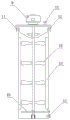
FIG. 2 is a schematic structural view of the cleaning tank of the present invention;
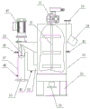
FIG. 3 is a schematic structural view of the air-floated oil removal tank of the present invention;
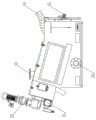
FIG. 4 is a schematic structural diagram of the high-efficiency coagulation device of the present invention;
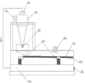
FIG. 5 is a schematic structural view of the cyclone sand remover of the present invention;
fig. 6 is a schematic structural diagram of the high-efficiency coagulation device of the present invention.
Detailed Description
The deoiling, desanding and dewatering device for the light oil sludge in the oil field comprises a cleaning tank 1, an oil storage tank 2, a stirring tank 3, a cyclone desander 4, an air flotation deoiling tank 5, a high-efficiency coagulator 6 and a serial spiral sludge dewatering machine 7; the upper portion of wasing jar 1 be equipped with the raw materials import, the bottom discharge mouth passes through pipeline A and cyclone 4's entry linkage, cyclone 4's bottom discharge mouth passes through pipeline B and is connected with the inlet of air supporting deoiling jar 5, the oil-out on air supporting deoiling jar 5 upper portion and 2 tube coupling of oil storage tank, the discharge gate of bottom passes through pipeline C and is connected with agitator tank 3's inlet, agitator tank 3's discharge gate has connected gradually high-efficient coagulation ware 6 and cluster spiral shell sludge dewaterer 7 through pipeline D.
The discharge port at the upper part of the high-efficiency coagulator 6 is connected with the feed inlet of the snail-stringing sludge dewatering machine 7, the filtrate outlet of the snail-stringing sludge dewatering machine 7 is connected with the clear water tank 8 through a pipeline, and the outer conveying pipeline of the clear water tank 8 is provided with a bypass pipeline E which is connected with the water mixing port at the top of the cleaning tank 1. And sewage pumps are arranged on the pipelines A, B, C and the external conveying pipelines of the clear water tank 8, and a variable frequency screw pump and a slurry pump 48 are arranged on the pipeline D and the incoming pipeline of the cleaning tank 1. Pressure transmitters PT are arranged in the cleaning tank 1, the oil storage tank 2, the stirring tank 3, the cyclone sand remover 4, the air flotation oil removing tank 5, the high-efficiency coagulator 6 and the clean water tank 8, and a temperature transmitter TT is also arranged in the cleaning tank 1.
In the device, a feeding pipeline F of a cleaning tank 1 is provided with a feeding port and a feeding tank I45 pipeline connection, a feeding port IV 44 of a pipeline coagulation device 37 is connected with a feeding tank II 46 pipeline connection, and a feeding port III 43 of a high-efficiency coagulation device 6 is connected with a feeding tank III 47 pipeline connection.
A medicament A, a medicament B and a medicament C are respectively arranged in the medicament adding tank I45, the medicament adding tank II 46 and the medicament adding tank III 47, the medicament A is a demulsifier, the medicament B is a PAC aqueous solution and a C medicament PAM aqueous solution, and meanwhile, a metering pump A, a metering pump B and a metering pump C are respectively arranged on outlet pipelines of the medicament adding tank I45, the medicament adding tank II 46 and the medicament adding tank III 47. And stirring speed reducers are respectively arranged on the medicine adding tank II 46 and the medicine adding tank III 47.
The cleaning tank 1 is characterized in that a stirring motor 9 is arranged at the center of the tank top of the cleaning tank 1, an output shaft of the stirring motor 9 penetrates through the tank top and is arranged in the tank body, and more than one group of blades 10 are fixed on the output shaft at intervals; the upper part of the cleaning tank 1 is provided with a raw material inlet 11, a water mixing port 12 and an exhaust port I13, and the bottom part is provided with a discharge port I14. Vertical spoilers 15 are installed at intervals around the inner wall of the cleaning tank 1, and an annular steam injection pipe 16 is installed on the bottom of the inner tank of the cleaning tank 1. The high-speed rotation of the stirring blades and the strong turbulent flow formed by the turbulent flow plates gather sufficient energy, and the mutual repulsion of ions is effectively destroyed. The properties and the arrangement state of solid particle groups are adjusted by conditioning and cleaning means such as steam cleaning, high-speed shearing dispersion, chemical demulsification, viscosity reduction and the like, so that the adsorption oil with high viscosity is desorbed and demulsified to be suitable for dehydration.
The cyclone sand remover comprises a feeding port V50, a primary liquid outlet V49, a cyclone separator 51, a slag outlet 52, a spring 53, an oscillator 54, a secondary liquid outlet V55, a filtrate tank 56, a screen plate 57 and a sand discharge port 64. The cyclone separator separates sand substances with heavier specific gravity from the materials by using a centrifugal separation principle, and discharges the sand substances after being filtered and dehydrated by a vibrating screen, wherein a primary liquid outlet V49 of the cyclone separator is connected with a filtrate tank 56 through a pipeline.
The air-flotation oil removing tank 5 is characterized in that a barrel-shaped partition plate is arranged at the center of the bottom in the air-flotation oil removing tank 5 to divide the air-flotation oil removing tank into an external separation cavity 17 and an internal aeration cavity 18, a cavitation aerator 19 is arranged at the center of the top of the tank, an output shaft of the cavitation aerator 19 is arranged in the aeration cavity 18, and an air dispersing impeller 20 is arranged at the tail end of the output shaft; the bottom of the air floatation oil removal tank 5 is provided with a feed inlet II 21 and a discharge outlet II 22, and a pipeline of the feed inlet II 21 penetrates through the partition plate to extend into the aeration cavity 18 and is arranged below the air dispersing impeller 20. Meanwhile, an observation port 23 and an exhaust port II 24 are arranged on the top of the air floatation oil removal tank 5, an oil outlet 25 is arranged on the upper portion of the air floatation oil removal tank, a drain outlet II 26 is arranged at the bottom of the air floatation oil removal tank, and a sampling port I27 and a sampling port II 28 are respectively arranged on the separation cavity 17 and the inner aeration cavity 18. The submersible type cavitation aerator is characterized in that the high-speed migration of a bottom air dispersing impeller is converted into water to form a vacuum area, air on the liquid surface is sucked into the water, bubbles are cut by the air dispersing impeller rotating at high speed, micro bubbles are generated along with the air dispersing impeller, and the micro bubbles rise to the upper surface in a spiral mode. Because of the pressure imbalance between the gas-water mixture and the liquid, a vertical upward buoyancy occurs, which quickly brings the oil substances with low specific gravity to the liquid surface.
The efficient coagulation device 6 is characterized in that the efficient coagulation device 6 comprises a pipeline coagulation device 37 and a flocculation tank 30, the flocculation tank 30 is located on a base 29, a variable-frequency speed reduction motor 31 is installed at the center of the top of the flocculation tank 30, an output shaft of the variable-frequency speed reduction motor 31 is connected with a stirring paddle III 32 and placed in the flocculation tank 30, an exhaust port III 33 is arranged at the top end of the flocculation tank 30, a discharge port III 34 is arranged at the upper part of the flocculation tank, a feed port III 35 is arranged at the lower part of the flocculation tank, and a drain outlet III 36 is arranged at the bottom of the flocculation tank. The feed inlet III 35 is connected with a pipeline coagulation device 37, the pipeline coagulation device 37 is an inverted U-shaped tube, one end of the inverted U-shaped tube is a feed inlet IV 38, a discharge outlet IV at the other end of the inverted U-shaped tube is connected with the feed inlet III 35 of the high-efficiency coagulation device 6, a stirring paddle IV 39 is arranged in a pipeline at one end of the feed inlet, and a driving motor 40 of the stirring paddle IV 39 is arranged at the top end of the inverted U-shaped tube. The flocculation tank 30 and the pipeline coagulation device 37 are respectively provided with a sample receiving port III 41 and a sample receiving port IV 42, and the inlet pipelines of the flocculation tank 30 and the pipeline coagulation device 37 are respectively provided with a medicine adding port III 43 and a medicine adding port IV 44. The pipeline coagulator is matched with a high-speed stirrer, and the flocculation tank is matched with a low-speed variable-frequency stirrer and a liquid level control system. The high-speed operation of the stirring blades in the tube forms strong turbulence, sufficient energy is gathered, the ions are quickly mixed with the B medicament while repulsive force among the ions is effectively destroyed, and repeated collision among the ions is enhanced and the ions are quickly aggregated. The design of the low velocity of flow low-speed stirring of flocculation vat is fit for the flocculation bridging characteristic of C medicament, when guaranteeing the flocculation group maximize, the flocculation group is along with stirring from the bottom come-up gradually, guarantees that the floc that has formed is not destroyed.
Floccules obtained after medicine adding reaction of raw materials in the high-efficiency coagulator 6 enter a snail-stringing sludge dewatering machine, a fixed ring and a movable ring are arranged in the snail-stringing sludge dewatering machine and are mutually stacked, a spiral speed reducing motor 60 and a movable ring speed reducing motor 61 are arranged outside the snail-stringing sludge dewatering machine, and a high-energy feed inlet VI 58, an exhaust outlet VI 59, a filtrate outlet VI 62 and a flushing electromagnetic valve 63 are arranged on the machine body. Floccules enter a mixing area of the snail-stringing sludge dehydrator and then enter a cavity of the snail-stringing scum dehydrator, a fixed ring and a movable ring are mutually laminated, a spiral speed reducing motor and a movable ring speed reducing motor drive two spiral shafts to penetrate through a filtering cavity formed in the spiral scum dehydrator, the upper end of the movable ring generates vertical linear motion under the action of an external driving and guiding device, the lower end of the movable ring generates left-right pendulum motion and is continuously staggered with the fixed ring to keep smooth filtering seams, the two spiral shafts in the cavity run side by side and are mutually rolled, and the floccules are gradually dewatered under the pushing and extruding of the spiral shafts to discharge mud cakes. Is suitable for separating transition layer and scum material.
The seed valve, the pump, the stirrer and the like in the treatment device are all connected with the control box through circuits, and the control mode is as follows:
(1) raw material pump control-cleaning tank liquid level control mode, high liquid level stop pump, low liquid level start pump, and interlock with metering pump (A medicament), start and stop at the same time;
(2) a cleaning tank discharge pump control-a cleaning tank liquid level control mode, a high liquid level pump starting, a low liquid level pump stopping, and a rotational flow desander liquid storage tank ultrahigh liquid level pump stopping;
(3) discharge pump control of cyclone desander-automatic control mode of liquid level of liquid storage tank of cyclone desander, high liquid level pump start, low liquid level pump stop, ultrahigh liquid level pump stop of air floatation oil removal tank;
(4) the air flotation oil removal tank discharge pump control-the air flotation oil outlet tank liquid level automatic control mode, high liquid level pump start, low liquid level pump stop, and the agitator tank ultrahigh liquid level pump stop;
(5) crude oil pump control-the automatic control mode of the liquid level of the crude oil tank, high liquid level pump start, low liquid level pump stop;
(6) discharge pump control of stirring tank- -automatic control mode of liquid level of high-efficiency coagulator, high liquid level stop pump, low liquid level start pump, and ultrahigh liquid level stop pump of filtrate tank. Interlocked with a metering pump (B medicament) and a metering pump (C medicament), and started and stopped simultaneously;
(7) clean water pump control-automatic control mode of filtrate tank liquid level, high liquid level pump start, low liquid level pump stop.
The utility model discloses an oil field light sump oil mud deoiling, desanding and dewatering device's application method is realized through following step:
(1) preparation of medicament
A medicament: adding a demulsifier into the medicine adding tank I45 to prepare a medicament A for later use;
and B, medicament: adding PAC dry powder into a medicine adding tank II 46, stirring, preparing a solution with the mass concentration of 5-10%, and preparing a medicament B for later use;
and C, medicament: adding PAM dry powder into a medicine adding tank III 47, stirring, and preparing into a solution with the mass concentration of 0.1-0.2% to prepare a medicament C for later use;
the specific models and the dosage of the demulsifier, the PAC dry powder and the PAM dry powder need to be screened and adjusted according to the characteristics of the sludge to be treated on site;
(2) feeding material
The oily sludge is sent into the high-efficiency cleaning tank 1 through a slurry pump 48, and hot water and an agent A are added at the same time;
(3) cleaning of
The method comprises the following steps of (1) quickly separating crude oil in the oily sludge in a cleaning tank by utilizing steam cleaning, high-speed shearing and dispersing and medicament demulsification principles;
(4) sand-water separation
Feeding the material treated in the step (3) into a cyclone desander 4, separating, dehydrating and discharging sand grains in sewage, and feeding oil-containing sewage into an air flotation oil removal tank 5;
(5) oil removal
The oily sewage treated in the step 4 enters an air flotation oil removal tank 5, crude oil in the sewage is quickly separated through air flotation, the crude oil enters an oil storage tank 2 through an upper oil outlet, the sewage enters a stirring tank 3 through a lower discharge port, and the sewage enters a high-efficiency coagulator 6 after being stirred;
(6) sludge dewatering
After being homogenized and added with the agent B and the agent C in the high-efficiency coagulator 6, the high-concentration sludge-containing sewage enters a screw sludge dewatering machine 7, dewatering is carried out through a sludge dewatering screw machine, dewatered sludge cakes are discharged outside, and clear water is pumped into an oil-water separation hot water circulating unit; thus completing the deoiling, desanding and dewatering of the dirty oil sludge.
Next, according to the production requirement, a complete set of 10m is made by the technical scheme of the application3The sewage sludge treatment device with the treatment capacity per hour carries out field experiments:
the field conditions are as follows:
a place: ternary south 4-9 combined station for second operation area of second oil production plant
The raw material sources are as follows: tank cleaning oil sludge
Production test time: from 15/9/2020 to 28/9/2020
Clear water source: 0.15Mpa tap water
A steam source: 0.4MPa saturated steam (supplied by an in situ steam generator)
Power source: 380V,50HZ (supplied by an on-site 30Kw electrical box)
The field treatment process of the oil sludge treatment comprises the following steps:
(1) preparation of medicament
A medicament: adding a demulsifier (KET-365 liquid floating agent is selected) into a medicine adding tank I45 (the effective volume is 0.5-1 m)3) To prepare the medicament A;
and B, medicament: pouring PAC (KET-531 polyaluminium chloride) dry powder into a medicine adding tank II 46 to prepare a 5-20% solution for later use (the effective volume of the medicine adding tank is 0.5-1 m)3) To prepare a medicament B;
and C, medicament: pouring PAM (KET-6655 cationic polyacrylamide) dry powder into a medicine adding tank III 47 to prepare 0.1-0.2% solution for later use (the effective volume of the medicine adding tank is 0.5-1 m)3) To prepare the medicament C;
(2) preheating: the cleaning tank is filled with clear water to a specified liquid level (1.3-1.5 m), the clear water is filled to a clear water tank (0.3-0.5 m), a steam heating valve is opened, and a cleaning tank stirrer (the speed ratio is 17-25/4-11 kw) is started when the temperature reaches 40-80 ℃;
(3) feeding and cleaning: setting the high liquid level of the cleaning tank to 1.7-1.9 m/low liquid level to 1.5-1.7 m, and starting to add medicine A (with a head of 30-50 m/flow 500 [ ] -E)1000L/h, the dosage is controlled to be 0.1-0.4 percent), a slurry pump is started (the head is 30-50 m/flow is 5-10 m)3When the control button is pulled to an 'automatic' gear, the water mixing valve of the cleaning tank is opened, and the clean water pump (with the lift of 30-50 m/flow of 20-30 m) is started3Setting the ultrahigh liquid level of a clear water tank to be 0.6-0.8 m/high liquid level 0.3-0.6 m/low liquid level 0.1-0.3 m, pulling a control button to an 'automatic' gear, starting a feeding and cleaning process, and controlling the detention time (2-4 min) of materials in a cleaning tank;
(4) sand removal: starting an oscillator (0.5-1.2 kw) of a cyclone sand remover (cyclone phi 80-150 mm) and a discharge pump (head 30-50 m/flow 20-30 m) of a cleaning tank3The control button is pulled to an 'automatic' gear);
(5) air flotation oil removal: starting a cavitation aerator (1-4 kw), starting a discharge pump (with a head of 30-50 m/flow rate of 20-30 m) of a liquid storage tank (with a set ultra-high liquid level of 0.6-0.8 m/high liquid level of 0.3-0.6 m/low liquid level of 0.1-0.3 m) of a cyclone sand remover3The control button is pulled to an 'automatic' gear);
(6) oil collection and transportation: setting the liquid level of a crude oil tank (the high liquid level is 1-1.5 m/the low liquid level is 0.2-0.5 m), and pulling a control button of a crude oil output pump to an 'automatic' gear;
(7) homogenizing: starting a stirrer of the stirring tank (the speed ratio is 39-64/3-7.5 kw), starting a discharge pump (the lift is 30-50 m/the flow is 20-30 m) of an air-floating oil removal tank (the set ultrahigh liquid level is 1.6-1.8 m/the high liquid level is 1.3-1.6 m/the low liquid level is 0.5-0.8 m)3The control button is pulled to an 'automatic' gear);
(8) sludge dewatering: setting the liquid level of the high-efficiency coagulation device (high liquid level 0.9-1 m/low liquid level 0.6-0.8 m), starting the stirrer of the high-efficiency coagulation device (speed ratio 17-25/0.4-1 kw), starting the flocculation tank stirrer (speed ratio 40-70/stirring speed 20-50 Hz/0.4-1 kw), starting the spiral sludge dewatering machine (spiral speed ratio 40-70/rotating speed 20-50 Hz/1-2 kw, active ring speed ratio 40-70/rotating speed 20-50 Hz/0.4-0.8 kw), starting the metering pump B (head 30-50 m/flow 500-1000L/h, dosage control 0.1-0.4%), C (head 30-50 m, flow control 500-1000L/h, dosage control 0.02%0.04 percent), a discharge pump of the stirring tank (with a head of 30-50 m/flow of 20-30 m)3And the control button is pulled to an 'automatic' gear), and the opening degrees of the clean water outward delivery valve and the watering valve are adjusted to keep the liquid level of the clean water tank balanced.
The project carries out the dirty oil sludge treatment in the ternary south 4-9 united station of the second operation area of Daqing oil extraction second factory, and compared with the centrifugal separation method, the project obtains better test effect, and the water content in the treated oily sludge is 51.8 percent, and the oil content is 1.89 x 10⁴mg/L, the oil content in the treated oily sewage is 5.82 mg/L, the suspended matter is 19mg/L, and the details are shown in an accessory detection report.
For a treatment capacity of 10m3The two process effects are compared:
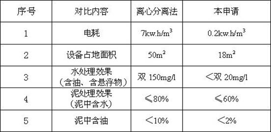
therefore, after the treatment by the technical scheme of the application, the oil content in the treated water is less than 20 mg/l; the suspended matter in the treated water is less than 20 mg/l; the oil content in the treated mud is less than 2 percent; the water content in the treated mud is less than 60 percent; the treated crude oil has no influence on the electric dehydration system of the combined station.
Claims (9)
1. The deoiling, desanding and dewatering device for the light oil sludge of the oil field comprises a cleaning tank (1), an oil storage tank (2) and a stirring tank (3), and is characterized by further comprising a cyclone sand remover (4), an air flotation deoiling tank (5), a high-efficiency coagulator (6) and a tandem screw sludge dewatering machine (7); the upper portion of washing jar (1) be equipped with the raw materials import, the bottom discharge mouth passes through the entry linkage of pipeline A with whirl sand remover (4), the bottom discharge mouth of whirl sand remover (4) passes through pipeline B and is connected with the inlet of air supporting oil removal tank (5), the oil-out and oil storage tank (2) tube coupling on air supporting oil removal tank (5) upper portion, the discharge gate of bottom passes through pipeline C and is connected with the inlet of agitator tank (3), the discharge gate of agitator tank (3) has connected gradually high-efficient coagulation ware (6) and string spiral shell sludge dewaterer (7) through pipeline D.
2. The oil field light sludge deoiling, desanding and dewatering device as defined in claim 1, characterized in that the discharge port at the upper part of the high efficiency coagulation device (6) is connected with the feed port of the tandem sludge dewatering machine (7), the filtrate outlet of the tandem sludge dewatering machine (7) is connected with the clear water tank (8) by pipeline, the output pipeline of the clear water tank (8) is provided with a bypass pipeline E connected with the water mixing port at the top of the cleaning tank (1).
3. The deoiling, desanding and dewatering device for the light oil sludge in the oilfield according to claim 1, which is characterized in that a stirring motor (9) is installed on the center of the top of the cleaning tank (1), an output shaft of the stirring motor (9) penetrates through the top of the tank and is placed in the tank body, and more than one group of blades (10) are fixed on the output shaft at intervals; the upper part of the cleaning tank (1) is provided with a raw material inlet (11), a water mixing port (12) and an exhaust port I (13), and the bottom is provided with a discharge port I (14).
4. The deoiling, desanding and dewatering device for light oil sludge in oil field as claimed in claim 3, characterized in that the inner wall of the cleaning tank (1) is provided with spoilers (15) around the circumference, and the inner tank bottom of the cleaning tank (1) is provided with the annular steam jet pipe (16).
5. The deoiling, desanding and dewatering device for the light oil sludge in the oil field as claimed in claim 1, wherein a barrel-shaped partition is arranged at the center of the bottom in the air-flotation oil removing tank (5) to divide the oil-flotation oil removing tank into an external separation cavity (17) and an internal aeration cavity (18), a cavitation aerator (19) is arranged at the center of the top of the tank, an output shaft of the cavitation aerator (19) is arranged in the aeration cavity (18), and an air-dispersing impeller (20) is arranged at the tail end of the output shaft; the bottom of the air floatation oil removal tank (5) is provided with a feed inlet II (21) and a discharge outlet II (22), and a pipeline of the feed inlet II (21) penetrates through the partition plate to extend into the aeration cavity (18) and is arranged below the air dispersing impeller (20).
6. The deoiling, desanding and dewatering device for light oil sludge in oil field as claimed in claim 5, wherein the tank top of the air-floating oil-removing tank (5) is provided with an observation port (23) and an exhaust port II (24), the upper part is provided with an oil outlet (25), the bottom is provided with a sewage outlet II (26), and the separation chamber (17) and the internal aeration chamber (18) are respectively provided with a sampling port I (27) and a sampling port II (28).
7. The deoiling, desanding and dewatering device for the light oil sludge in the oil field as claimed in claim 1, wherein the high-efficiency coagulation device (6) is composed of a pipeline coagulation device (37) and a flocculation tank (30), the flocculation tank (30) is seated on a base (29), a variable-frequency speed reduction motor (31) is installed at the center of the top of the flocculation tank (30), an output shaft of the variable-frequency speed reduction motor (31) is connected with a stirring slurry III (32) and is placed in the flocculation tank (30), an exhaust port III (33) is arranged at the top end of the flocculation tank (30), a discharge port III (34) is arranged at the upper part, a feed port III (35) is arranged at the lower part, and a drain outlet III (36) is arranged at the bottom part.
8. The oil field light dirty oil sludge deoiling, desanding and dewatering device as claimed in claim 7, characterized in that the feed port iii (35) is connected with a pipe coagulation device (37), the pipe coagulation device (37) is an inverted U-shaped pipe, one end of the inverted U-shaped pipe is a feed port iv (38), the discharge port iv at the other end is connected with the feed port iii (35) of the flocculation tank (30), a stirring paddle iv (39) is arranged in the pipe at one end of the feed port, and a driving motor (40) of the stirring paddle iv (39) is arranged at the top end of the inverted U-shaped pipe.
9. The deoiling, desanding and dewatering device for light dirty oil sludge in oil field according to claim 8, characterized in that the incoming pipeline F of the cleaning tank (1) is provided with a chemical feeding port connected with the pipeline of the chemical feeding tank i (45), the chemical feeding port iv (44) of the pipeline coagulation device (37) is connected with the pipeline of the chemical feeding tank ii (46), and the chemical feeding port iii (43) of the high-efficiency coagulation device (6) is connected with the pipeline of the chemical feeding tank iii (47).
Priority Applications (1)
| Application Number | Priority Date | Filing Date | Title |
|---|---|---|---|
| CN202022621342.9U CN213771799U (en) | 2020-11-13 | 2020-11-13 | Deoiling, desanding and dewatering device for light oil sludge in oil field |
Applications Claiming Priority (1)
| Application Number | Priority Date | Filing Date | Title |
|---|---|---|---|
| CN202022621342.9U CN213771799U (en) | 2020-11-13 | 2020-11-13 | Deoiling, desanding and dewatering device for light oil sludge in oil field |
Publications (1)
| Publication Number | Publication Date |
|---|---|
| CN213771799U true CN213771799U (en) | 2021-07-23 |
Family
ID=76916277
Family Applications (1)
| Application Number | Title | Priority Date | Filing Date |
|---|---|---|---|
| CN202022621342.9U Active CN213771799U (en) | 2020-11-13 | 2020-11-13 | Deoiling, desanding and dewatering device for light oil sludge in oil field |
Country Status (1)
| Country | Link |
|---|---|
| CN (1) | CN213771799U (en) |
Cited By (1)
| Publication number | Priority date | Publication date | Assignee | Title |
|---|---|---|---|---|
| CN112390507A (en) * | 2020-11-13 | 2021-02-23 | 大庆科恩特环保科技发展有限公司 | Deoiling, desanding and dewatering device and method for light oil sludge of oil field |
-
2020
- 2020-11-13 CN CN202022621342.9U patent/CN213771799U/en active Active
Cited By (1)
| Publication number | Priority date | Publication date | Assignee | Title |
|---|---|---|---|---|
| CN112390507A (en) * | 2020-11-13 | 2021-02-23 | 大庆科恩特环保科技发展有限公司 | Deoiling, desanding and dewatering device and method for light oil sludge of oil field |
Similar Documents
| Publication | Publication Date | Title |
|---|---|---|
| CN102642884B (en) | Oil-contained sewage treatment method and eddy energy fast-cyclone separating system of special equipment for method | |
| CN106007209A (en) | Oil removing pretreatment technology for petroleum oil refining wastewater | |
| CN205442919U (en) | Oil field extraction water processing system | |
| CN105731689B (en) | The processing method and processing device of the high poly- high-sulfur oily wastewater in oil field | |
| CN113149280B (en) | High-efficient sewage treatment system | |
| CN107721025A (en) | The processing method of a kind of oil-containing and oil wastewater and its efficiently separate system | |
| CN105855067B (en) | A kind of unpowered flotation device | |
| CN213771799U (en) | Deoiling, desanding and dewatering device for light oil sludge in oil field | |
| CN103030229B (en) | Oily wastewater treatment device and treatment method in steel industry | |
| JP4246087B2 (en) | Oil-containing wastewater treatment equipment | |
| CN111573871A (en) | Closed oily sewage treatment device and process | |
| CN208265916U (en) | A kind of high efficiency composition EPS reactor | |
| CN206886842U (en) | A kind of water-oil separating chemicals dosing plant | |
| CN112390507A (en) | Deoiling, desanding and dewatering device and method for light oil sludge of oil field | |
| CN206607098U (en) | One kind cleaning HDPE reclaimed materials sewage disposal systems | |
| CN202823268U (en) | Slurring device for white mud or acetylene sludge | |
| CN214734955U (en) | Pretreatment system for kitchen waste biogas slurry | |
| CN213865706U (en) | High-efficiency coagulation centrifugal air-float process oily sewage treatment device | |
| CN208648945U (en) | Compound oil partiting precipitation pool | |
| CN110204104B (en) | Suspension medium layer filtration system based on mechanical stirring layering | |
| CN204550162U (en) | Sewage purifying and treating device | |
| CN207511982U (en) | A kind of oil-containing and Fat wastewater treatment are with efficiently separating system | |
| CN204981223U (en) | Novel cavitation air supporting machine | |
| CN205761807U (en) | A kind of Novel unpowered flotation device | |
| CN205367974U (en) | Oil field height gathers high -sulfur oily water treatment device |
Legal Events
| Date | Code | Title | Description |
|---|---|---|---|
| GR01 | Patent grant | ||
| GR01 | Patent grant |