Laser cutting machine capable of cutting materials in two directions simultaneously
Technical Field
The utility model relates to a laser cutting machine technical field specifically is a two-way laser cutting machine who cuts the material simultaneously.
Background
The laser cutting machine has very wide application range and very good cutting effect. However, the cutting machine can not cut any materials, some materials have great damage to the laser cutting machine, when some large materials are required to be cut, multi-part cutting is required, common cutting equipment consumes time and labor, and the quantity requirement of the modern market cannot be met while the quality is finished, so that the laser cutting machine capable of cutting materials in two directions is indispensable.
In summary, in the conventional laser cutting machine, since the structure of the device is single, the device can only move in a single direction when cutting a material, which brings much inconvenience to the cutting of the material and increases the operation time.
SUMMERY OF THE UTILITY MODEL
An object of the utility model is to provide a two-way laser cutting machine who cuts material simultaneously to propose current laser cutting machine in solving above-mentioned background art, because the device's structure is comparatively single, can only carry out the motion of single direction when cutting the material, bring a great deal of inconvenience for cutting the material, increased operating time's problem.
In order to achieve the above object, the utility model provides a following technical scheme: a laser cutting machine capable of cutting materials simultaneously in two directions comprises a reinforcing base and vertical rods, wherein damping springs are welded inside the reinforcing base, vertical feet are arranged below the reinforcing base, vertical columns are arranged above the reinforcing base, lifting rods are connected above the vertical columns, cross beams are arranged above the lifting rods, cross rods are arranged on the left sides of the cross beams, telescopic rods are connected to the left sides of the cross rods, supporting beams are arranged on the left sides of the telescopic rods, sliding blocks are connected to the left ends of the supporting beams, rigid sliding plates are arranged on the outer sides of the sliding blocks, balls are connected to the left sides of the sliding blocks, fixed plates are connected to the left sides of the fixed plates, cutting heads are arranged on the outer sides of the left sides of the movable plates, and the vertical rods are arranged above the reinforcing base, and a processing table is arranged above the upright stanchion, and an antiskid plate is arranged above the processing table.
Preferably, the damping springs and the reinforcing base are welded, and the damping springs are arranged in the reinforcing base at equal intervals.
Preferably, the lifting rod is connected with the upright post in a lifting mode, and the cross beam is vertically arranged at the lower end of the lifting rod.
Preferably, the telescopic rod is in telescopic connection with the cross rod, and the outer diameter of the cross rod is the same as that of the cross beam.
Preferably, the sliding block and the ball are connected in a translational rolling manner, and the rigid sliding plates are arranged on the outer side of the sliding block in a vertical symmetry manner.
Preferably, the cutting head is connected with the moving plate through a clamping groove, and the cutting head can be movably arranged at the left end of the moving plate.
Preferably, the antiskid plate is connected with the processing table through a buckle, and the size of the antiskid plate is the same as that of the processing table.
Compared with the prior art, the beneficial effects of the utility model are that: the laser cutting machine capable of cutting materials bidirectionally and simultaneously,
(1) the sliding block is arranged, so that the fixed plate can slide to a proper position through the sliding block, the position can be freely adjusted to cut at will according to the cutting angle required by the material, and the material can be cut in multiple directions through bidirectional arrangement, so that the cutting time is greatly reduced, and the flexibility of the device is improved;
(2) the lifting rod is arranged, so that the cross beam can be lifted to a proper position through the lifting rod, the position can be reasonably adjusted according to the size of a cut material, the large material can be conveniently cut, and the position can be timely adjusted according to the irregular state of the material, so that the cutting time can be shortened during cutting, and the working efficiency of the device is improved;
(3) be provided with the telescopic link, can pass through the telescopic link with a supporting beam like this and stretch out and draw back to suitable position, according to the size of material cutting, the size of adjusting suitable position and being convenient for according to the requirement is cut, has improved the device's work efficiency.
Drawings
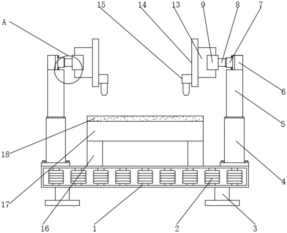
Fig. 1 is a schematic front view of the internal structure of the present invention;
FIG. 2 is a schematic view of the slide block planing-off structure of the present invention;
fig. 3 is a schematic top view of the present invention;
fig. 4 is an enlarged schematic structural diagram of a in fig. 1 according to the present invention.
In the figure: 1. reinforcing the base; 2. a damping spring; 3. standing; 4. a column; 5. a lifting rod; 6. a cross beam; 7. a cross bar; 8. a telescopic rod; 9. a support beam; 10. a slider; 11. a rigid sliding plate; 12. a ball bearing; 13. a fixing plate; 14. moving the plate; 15. a cutting head; 16. erecting a rod; 17. a processing table; 18. an antiskid plate.
Detailed Description
The technical solutions in the embodiments of the present invention will be described clearly and completely with reference to the accompanying drawings in the embodiments of the present invention, and it is obvious that the described embodiments are only some embodiments of the present invention, not all embodiments. Based on the embodiments in the present invention, all other embodiments obtained by a person skilled in the art without creative work belong to the protection scope of the present invention.
Referring to fig. 1-4, the present invention provides a technical solution: a laser cutting machine capable of cutting materials simultaneously in two directions is disclosed, as shown in figures 1, 2 and 3, a damping spring 2 is welded in a reinforcing base 1, the damping spring 2 is welded with the reinforcing base 1, the damping spring 2 is arranged in the reinforcing base 1 at equal intervals, and the damping spring 2 is arranged, so that when the device works, vibration force generated by movement can be relieved through the damping spring 2, parts of the device are effectively protected from being damaged, the service life of the device is prolonged, stand legs 3 are arranged below the reinforcing base 1, stand columns 4 are arranged above the reinforcing base 1, lifting rods 5 are connected above the stand columns 4, the lifting rods 5 are connected with the stand columns 4 in a lifting mode, a cross beam 6 is vertically arranged at the lower end of the lifting rods 5 and provided with the lifting rods 5, and therefore the cross beam 6 can be lifted to a proper position through the lifting rods 5, according to the size of cutting material, reasonable adjusting position is convenient for also can cut it to larger-scale material, also can be according to the irregular state of material, timely adjusting position, make the time of cutting can be reduced when the cutting, improve the device's work efficiency, the top of lifter 5 all is provided with crossbeam 6, and the left of crossbeam 6 all is provided with horizontal pole 7, the left of horizontal pole 7 all is connected with telescopic link 8, be telescopic connection between telescopic link 8 and the horizontal pole 7, and the external diameter of horizontal pole 7 is the same with the external diameter of crossbeam 6, be provided with telescopic link 8, can stretch out and draw back supporting beam 9 to suitable position through telescopic link 8 like this, according to the size of material cutting, the size of being convenient for according to the requirement in the suitable position of adjustment is cut, the device's work efficiency has been improved, and supporting beam 9 all is provided with supporting beam 9 in telescopic link 8's left.
As shown in fig. 1, 2, 3 and 4, the left ends of the supporting beams 9 are connected with sliding blocks 10, the sliding blocks 10 are connected with balls 12 in a translation rolling manner, and rigid sliding blocks 11 are symmetrically arranged up and down on the outer sides of the sliding blocks 10, the sliding blocks 10 are arranged, so that a fixed plate 13 can slide to a proper position through the sliding blocks 10, the position can be freely adjusted and cut freely according to the required cutting angle of the material, the cutting time is greatly reduced by bidirectional arrangement, and the material can be cut in multiple directions, the flexibility of the device is improved, the outer sides of the sliding blocks 10 are provided with the rigid sliding plates 11, the left ends of the sliding blocks 10 are connected with the balls 12, the left ends of the balls 12 are connected with the fixed plate 13, the sliding of the sliding can be effectively increased by arranging the balls 12, and the left ends of the fixed plate 13 are connected with a moving plate 14, and the cutting head 15 is arranged at the outer side of the left side of the moving plate 14, the cutting head 15 is connected with the moving plate 14 through a clamping groove, and a cutting head 15 is movably provided at the left end of the moving plate 14, provided with the cutting head 15, because of the bayonet connection between the cutting head 15 and the moving plate 14, when the cutting head 15 is damaged or worn, is convenient to replace and maintain, is convenient for workers to install and disassemble, the upright posts 16 are all arranged above the reinforced base 1, a processing table 17 is arranged above the upright rod 16, an antiskid plate 18 is arranged above the processing table 17, the antiskid plate 18 is connected with the processing table 17 in a buckling way, and the size of the antiskid plate 18 is the same as that of the processing table 17, and the antiskid plate 18 is arranged, so that the antiskid plate 18 can effectively prevent materials from sliding, quality problems and material damage are avoided, and the antiskid property of the device is improved.
The working principle is as follows: when the laser cutting machine capable of cutting materials bidirectionally and simultaneously is used, firstly, the device is moved to a required use position, an external power supply is switched on, then the materials to be cut are placed on a processing table 17 and are reinforced and locked, then a cross beam 6 is lifted to a proper position through a lifting rod 5, the proper height is adjusted according to the size of the materials, then a supporting beam 9 is stretched to a proper position through a telescopic rod 8 and is reasonably adjusted according to the required size, then a fixed plate 13 is slid to a proper position through a sliding block 10, cutting work is carried out according to the position adjustment and the positioning of the materials, finally, a cutting head 15 is adjusted to a proper angle so as to be convenient for cutting according to requirements, and all work is finished.
The terms "central," "longitudinal," "lateral," "front," "rear," "left," "right," "vertical," "horizontal," "top," "bottom," "inner," "outer," and the like are used in the orientation or positional relationship indicated in the drawings for ease of description, but are not intended to indicate or imply that the device or element so referred to must have a particular orientation, be constructed and operated in a particular orientation, and are not to be considered limiting of the scope of the invention.
Although the present invention has been described in detail with reference to the foregoing embodiments, it will be apparent to those skilled in the art that modifications may be made to the embodiments or portions thereof without departing from the spirit and scope of the invention.