CN213742414U - Masonry mold - Google Patents
Masonry mold Download PDFInfo
- Publication number
- CN213742414U CN213742414U CN202022610615.XU CN202022610615U CN213742414U CN 213742414 U CN213742414 U CN 213742414U CN 202022610615 U CN202022610615 U CN 202022610615U CN 213742414 U CN213742414 U CN 213742414U
- Authority
- CN
- China
- Prior art keywords
- masonry
- rod
- base
- template
- hinged
- Prior art date
- Legal status (The legal status is an assumption and is not a legal conclusion. Google has not performed a legal analysis and makes no representation as to the accuracy of the status listed.)
- Active
Links
- 229910000831 Steel Inorganic materials 0.000 claims abstract description 32
- 239000010959 steel Substances 0.000 claims abstract description 32
- 239000011449 brick Substances 0.000 abstract description 14
- 238000010276 construction Methods 0.000 abstract description 9
- 239000011505 plaster Substances 0.000 abstract description 4
- 238000000034 method Methods 0.000 description 2
- 230000009286 beneficial effect Effects 0.000 description 1
- 238000010586 diagram Methods 0.000 description 1
- 201000010099 disease Diseases 0.000 description 1
- 208000037265 diseases, disorders, signs and symptoms Diseases 0.000 description 1
- 238000009434 installation Methods 0.000 description 1
- 238000010030 laminating Methods 0.000 description 1
- 239000000463 material Substances 0.000 description 1
- 238000012986 modification Methods 0.000 description 1
- 230000004048 modification Effects 0.000 description 1
- 239000004570 mortar (masonry) Substances 0.000 description 1
- 238000006467 substitution reaction Methods 0.000 description 1
Images

Landscapes
- Conveying And Assembling Of Building Elements In Situ (AREA)
Abstract
The utility model discloses a masonry mold, which comprises two horizontally arranged and mutually parallel bases, wherein one end of each base is hinged with a vertical rod, and the other end of each base is hinged with a telescopic rod; one end of the telescopic rod is hinged with the base, and the other end of the telescopic rod is hinged with the upper part of the upright rod, so that the base, the upright rod and the telescopic rod form a triangular structure; the masonry plastering template is arranged between the two vertical rods, the length direction of the masonry plastering template is perpendicular to the vertical rods, and the masonry plastering template is connected with the two vertical rods in a sliding fit manner, so that the masonry plastering template can slide along the length direction of the vertical rods. Through adopting the telescopic link to come to adjust the straightness that hangs down of building by laying bricks or stones the template of plastering, follow gliding building by laying bricks or stones of steel pipe simultaneously and plaster the template and can wholly upper and lower and control the translation, the adjustment is simple, and the efficiency of construction is high, convenient to use.
Description
Technical Field
The utility model belongs to the technical field of architectural equipment, very much relate to a masonry mold.
Background
At present, with the advance of urbanization process, the requirement of an owner on the quality of a house is higher and higher, the masonry process of workers is poor, the sizes of bricks are different, and the thickness of mortar is not well controlled, so that the masonry quality has the phenomena of unattractive appearance, more common diseases and the like, a large amount of reworking is caused to the subsequent plastering project and installation project, the manpower and the time are spent, the material is wasted, and the construction period and the construction cost of a project construction unit are not guaranteed.
SUMMERY OF THE UTILITY MODEL
To the not enough of above-mentioned prior art, the utility model aims to solve the technical problem that: how to provide a masonry mould that is convenient to build by laying bricks or stones to can detect the roughness of plastering.
In order to solve the technical problem, the utility model discloses a following technical scheme:
a masonry mold comprises two bases which are horizontally arranged and are parallel to each other, wherein one end of each base is hinged with a vertical rod, and the other end of each base is hinged with a telescopic rod; one end of the telescopic rod is hinged with the base, and the other end of the telescopic rod is hinged with the upper part of the upright rod, so that the base, the upright rod and the telescopic rod form a triangular structure; the masonry plastering template is arranged between the two vertical rods, the length direction of the masonry plastering template is perpendicular to the vertical rods, and the masonry plastering template is connected with the two vertical rods in a sliding fit manner, so that the masonry plastering template can slide along the length direction of the vertical rods.
Furthermore, the upper end and the lower end of the vertical rod are respectively provided with a sliding hole, the axial direction of each sliding hole is consistent with the length direction of the base, sliding rods are arranged in the sliding holes in a sliding fit manner, a steel pipe is fixedly connected between the two sliding rods, and the steel pipe is positioned on one side of the vertical rod, which is far away from the telescopic rod; under the sliding fit of the sliding rod and the sliding hole, the steel pipe can be far away from or close to the upright rod; the steel pipe is sleeved with a sliding sleeve in a sliding fit mode, and the sliding sleeve is fixedly connected with the masonry plastering template, so that the steel pipe can drive the masonry plastering template to be far away from or close to the vertical rod.
Further, the telescopic link includes the connecting rod of two coaxial settings, and the one end that two connecting rods are adjacent is equipped with the steel axle be equipped with the external screw thread on the steel axle, two steel axles link to each other through a threaded sleeve, rotate the sleeve, can make two steel axles be close to each other or keep away from.
Furthermore, fixing devices for fixing the base are further arranged at two ends of the base.
Further, the fixing device is an anchor rod.
Compared with the prior art, the utility model discloses the beneficial effect who gains: through adopting the telescopic link to come to adjust the straightness that hangs down of building by laying bricks or stones the template of plastering, follow gliding building by laying bricks or stones of steel pipe simultaneously and plaster the template and can wholly upper and lower and control the translation, the adjustment is simple, and the efficiency of construction is high, convenient to use.
Drawings
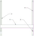
Fig. 1 is a schematic view of the structure of the present invention;
fig. 2 is a left side view structure diagram of the present invention;
the reference numbers illustrate: 1 base, 2 pole settings, 3 telescopic links, 4 masonry plaster templates, 5 slide bars, 6 steel pipes, 7 sliding sleeves, 8 steel shafts, 9 sleeves, 10 fixing device.
Detailed Description
The present invention will be described in further detail with reference to the accompanying drawings.
Example (b): referring to fig. 1-2, a masonry mold comprises two horizontally arranged and parallel bases 1, wherein one end of each base 1 is hinged with a vertical rod 2, and the other end of each base 1 is hinged with a telescopic rod 3; one end of the telescopic rod 3 is hinged with the base 1, and the other end of the telescopic rod is hinged with the upper part of the upright rod 2, so that the base 1, the upright rod 2 and the telescopic rod 3 form a triangular structure; the telescopic rod 3 can adjust the verticality of the vertical rod 2. The telescopic rod 3 comprises two connecting rods which are coaxially arranged, a steel shaft 8 is arranged at one end where the two connecting rods are adjacent, external threads are arranged on the steel shaft 8, the two steel shafts 8 are connected through a threaded sleeve 9, and the sleeve 9 is rotated to enable the two steel shafts 8 to be close to or far away from each other.
Specifically, each base 1 corresponds to one telescopic rod 3 and one vertical rod 2 to form a triangular support structure, and in order to improve the connection stability between the two support structures, inclined struts or connecting rods can be installed according to actual needs to reinforce the support structure so as to keep the whole support structure stable.
The masonry plastering template 4 is arranged between the two vertical rods 2, the length direction of the masonry plastering template 4 is perpendicular to the vertical rods 2, and the masonry plastering template 4 is connected with the two vertical rods 2 in a sliding fit manner, so that the masonry plastering template 4 can slide along the length direction of the vertical rods 2. Specifically, the upper end and the lower end of the vertical rod 2 are respectively provided with a sliding hole, the axial direction of each sliding hole is consistent with the length direction of the base 1, a sliding rod 5 is arranged in each sliding hole in a sliding fit manner, a steel pipe 6 is fixedly connected between the two sliding rods 5, and the steel pipe 6 is positioned on one side of the vertical rod 2, which is far away from the telescopic rod 3; under the sliding fit of the sliding rod 5 and the sliding hole, the steel pipe 6 can be far away from or close to the upright rod 2; the steel pipe 6 is sleeved with a sliding sleeve 7 in a sliding fit mode, and the sliding sleeve 7 is fixedly connected with the masonry plastering template 4, so that the steel pipe 6 can drive the masonry plastering template 4 to be far away from or close to the vertical rod 2. Like this, when the construction, can be convenient will build by laying bricks or stones plastering template 4 and remove to the position of waiting to build by laying bricks or stones, through 3 adjustment pole settings 2's of telescopic link straightness that hangs down to make and build by laying bricks or stones plastering template 4 and keep vertical, when building by laying bricks or stones, building block laminating is built by laying bricks or stones plastering template 4 and is built by laying bricks or stones, can guarantee the holistic straightness that hangs down of masonry structure, has saved numerous and diverse operations such as guy wire, li pi number pole, the highly unified level of brickwork, the facade is level and smooth, has accelerated the construction progress, has guaranteed construction quality. And because masonry plastering template 4 can move about, when masonry is finished plastering, whether the facade of plastering is level or not can also be detected by adjusting masonry plastering template 4, convenient and fast, easy operation.
Fixing devices 10 for fixing the base 1 are further arranged at two ends of the base 1. The fixing device 10 is an anchor rod. The fixing base 1 is convenient to fix, the masonry plastering template 4 is kept stable, the masonry structure is smoother, and the quality is more reliable.
The utility model discloses an adopt the telescopic link to come to adjust the straightness that hangs down of building by laying bricks or stones the template of plastering, follow gliding building by laying bricks or stones of steel pipe simultaneously and plaster the template and can wholly about and control the translation, the adjustment is simple, the efficiency of construction is high, convenient to use.
Finally, it should be noted that the above embodiments are only used for illustrating the technical solutions of the present invention and not for limiting the technical solutions, and those skilled in the art should understand that those modifications or equivalent substitutions can be made to the technical solutions of the present invention without departing from the spirit and scope of the technical solutions, and all should be covered in the scope of the claims of the present invention.
Claims (5)
1. A masonry mold is characterized by comprising two bases which are horizontally arranged and are parallel to each other, wherein one end of each base is hinged with a vertical rod, and the other end of each base is hinged with a telescopic rod; one end of the telescopic rod is hinged with the base, and the other end of the telescopic rod is hinged with the upper part of the upright rod, so that the base, the upright rod and the telescopic rod form a triangular structure; the masonry plastering template is arranged between the two vertical rods, the length direction of the masonry plastering template is perpendicular to the vertical rods, and the masonry plastering template is connected with the two vertical rods in a sliding fit manner, so that the masonry plastering template can slide along the length direction of the vertical rods.
2. A masonry mold according to claim 1, wherein the vertical rod is provided at its upper and lower ends with a slide hole, the axial direction of the slide hole is the same as the length direction of the base, slide rods are slidably fitted in the slide holes, a steel pipe is fixedly connected between the two slide rods, and the steel pipe is located on the side of the vertical rod away from the telescopic rod; under the sliding fit of the sliding rod and the sliding hole, the steel pipe can be far away from or close to the upright rod; the steel pipe is sleeved with a sliding sleeve in a sliding fit mode, and the sliding sleeve is fixedly connected with the masonry plastering template, so that the steel pipe can drive the masonry plastering template to be far away from or close to the vertical rod.
3. A masonry mold according to any one of claims 1-2, wherein said telescoping rod comprises two coaxially disposed connecting rods, a steel shaft being provided at the end adjacent the two connecting rods, said steel shaft being externally threaded, the two steel shafts being connected by a threaded sleeve, the sleeve being rotatable to move the two steel shafts towards and away from each other.
4. A masonry mold according to claim 3, wherein fixing means for fixing the base are further provided at both ends of said base.
5. A masonry mold according to claim 4, wherein the fixing means are anchor rods.
Priority Applications (1)
| Application Number | Priority Date | Filing Date | Title |
|---|---|---|---|
| CN202022610615.XU CN213742414U (en) | 2020-11-12 | 2020-11-12 | Masonry mold |
Applications Claiming Priority (1)
| Application Number | Priority Date | Filing Date | Title |
|---|---|---|---|
| CN202022610615.XU CN213742414U (en) | 2020-11-12 | 2020-11-12 | Masonry mold |
Publications (1)
| Publication Number | Publication Date |
|---|---|
| CN213742414U true CN213742414U (en) | 2021-07-20 |
Family
ID=76823485
Family Applications (1)
| Application Number | Title | Priority Date | Filing Date |
|---|---|---|---|
| CN202022610615.XU Active CN213742414U (en) | 2020-11-12 | 2020-11-12 | Masonry mold |
Country Status (1)
| Country | Link |
|---|---|
| CN (1) | CN213742414U (en) |
Cited By (2)
| Publication number | Priority date | Publication date | Assignee | Title |
|---|---|---|---|---|
| CN113818699A (en) * | 2021-09-09 | 2021-12-21 | 中冶天工集团有限公司 | A new tool and method for ensuring vertical flatness in masonry engineering |
| CN113944319A (en) * | 2021-09-29 | 2022-01-18 | 中国化学工程第六建设有限公司 | Novel shaping combined template for wall column and construction method thereof |
-
2020
- 2020-11-12 CN CN202022610615.XU patent/CN213742414U/en active Active
Cited By (2)
| Publication number | Priority date | Publication date | Assignee | Title |
|---|---|---|---|---|
| CN113818699A (en) * | 2021-09-09 | 2021-12-21 | 中冶天工集团有限公司 | A new tool and method for ensuring vertical flatness in masonry engineering |
| CN113944319A (en) * | 2021-09-29 | 2022-01-18 | 中国化学工程第六建设有限公司 | Novel shaping combined template for wall column and construction method thereof |
Similar Documents
| Publication | Publication Date | Title |
|---|---|---|
| CN207144503U (en) | A kind of thickness of concrete floor control device | |
| CN208100686U (en) | Residential fire flue makes mold | |
| CN207004068U (en) | A kind of gray seam thickness controls instrument | |
| CN207794608U (en) | A kind of adjustable support for shuttering of movement for groove construction column | |
| CN215168026U (en) | Template supporting structure of post-cast suspended beam plate | |
| CN206158117U (en) | Wall ground floating screed instrument of making level | |
| CN209468925U (en) | Turnover Shear Wall Horizontal Rebar Locator | |
| CN116927519A (en) | Wall body positioner for assembled building | |
| CN204592560U (en) | A kind of adjustable cable crane span structure support supported for curved wall | |
| CN204001309U (en) | A kind of syndeton of Multi-function light concrete curtain wall | |
| CN108560901A (en) | Fixing device for construction site scaffolding | |
| CN210369894U (en) | A prefabricated adjustable drop plate formwork support system | |
| CN203878943U (en) | Calibration device for brick wall and plaster layer construction standard | |
| CN215907403U (en) | Fine adjustment tool for supporting large steel formwork | |
| CN209457361U (en) | Scalable hanging basket | |
| CN213597031U (en) | Aluminum alloy template for urban underground pipe gallery | |
| CN206550391U (en) | A kind of electric drill auxiliary support apparatus | |
| CN214743833U (en) | Electromechanical installation is with a gallows system of combatting earthquake | |
| CN210918169U (en) | Outer frame in lighting well | |
| CN104612059B (en) | A kind of for concrete in mass building block lifting dabbing device and method | |
| CN207727805U (en) | A kind of reinforced perps unit of fabricated shear wall anchor pole | |
| CN217734448U (en) | Energy-saving prefabricated shear wall for building construction | |
| CN209103691U (en) | PC component arrow logo specific purpose tool | |
| CN206784806U (en) | One kind is easily installed formula GRC partition wall glassy bricks | |
| CN113565319A (en) | A fine-tuning tool and construction method for large-scale steel formwork support |
Legal Events
| Date | Code | Title | Description |
|---|---|---|---|
| GR01 | Patent grant | ||
| GR01 | Patent grant |