Leg connecting rod device of toy bicycle
Technical Field
The utility model relates to a toy bicycle technical field especially relates to a toy bicycle shank connecting rod device.
Background
The toy bicycle is called a child bicycle, and is a bicycle suitable for 4-8-year-old children to ride, the maximum saddle height is 435-635 mm, and the children can ride the bicycle by means of a driving mechanism acting on a rear wheel. Various wheel diameters and various styles with or without balance wheels. Children's bicycles cannot be used for road riding. The children bicycle is generally very small in size and overlarge in size, and a child cannot tightly hold a hand brake during braking, so that the child cannot brake the bicycle. In addition, the braking force is not less than 50N, otherwise, the vehicle can not be braked, and harm is brought to children. Children's bicycles are also equipped with a protective wheel (balance wheel) which enables the rider to keep balance.
Parents buy children's bicycle for children in order to let them study how to ride the bicycle, therefore when children are bigger a bit, parents will lift off children's bicycle's stabilizer wheel, let children practise to ride the bicycle, if find that children still can not master the balance this moment, still need to install the bicycle wheel, very troublesome to be unfavorable for children's study bicycle. Based on the existing problems, a leg link device of a toy bicycle is provided.
SUMMERY OF THE UTILITY MODEL
Objects of the invention
For solving the technical problem who exists among the background art, the utility model provides a toy bicycle shank connecting rod device through setting up supporting component, can solve the stabilizer wheel and dismantle inconvenient problem, can promote child to study simultaneously and ride the bicycle.
(II) technical scheme
The utility model provides a leg connecting rod device of a toy bicycle, which comprises a frame, a chain and a supporting component;
the front part of the frame is provided with a handle head; a saddle is arranged in the middle of the frame; the bottom of the frame is rotatably provided with a front wheel which is positioned below the handle head; the middle part of the frame is provided with a first chain wheel; a second chain wheel is arranged at the rear part of the frame and is in transmission connection with the first chain wheel through a chain; the second chain wheel is provided with a rear wheel; the first chain wheel is provided with a pedal; the rear part of the frame is provided with a connecting plate which is positioned above the rear wheel; a support plate is arranged on one transverse side of the connecting plate and is positioned above the rear wheel;
the support components are provided with two groups, the two groups of support components are respectively arranged at the longitudinal two sides of the support plate, the support plate comprises a placing cylinder, a sliding plate, a lead screw, a first gear, a rotating shaft, a second gear, a support leg, a universal wheel, a connecting rod and a mounting plate, the placing cylinder is arranged at the longitudinal two sides of the support plate, the mounting plate is arranged on the inner wall of the placing cylinder, the sliding plate is arranged on the inner wall of the placing cylinder in a sliding manner, the sliding plate is positioned below the mounting plate, the lead screw is rotatably arranged on the mounting plate, the lead screw penetrates through the mounting plate, the lead screw is in threaded connection with the sliding plate, the first gear is arranged at the upper end of the lead screw, the first gear is positioned above the mounting plate, the rotating shaft penetrates through one lateral side of the placing cylinder, the second gear is arranged on the rotating shaft, the second gear is in meshed connection with the first gear, the support leg is rotatably arranged on the inner wall of the placing cylinder, and the support leg is positioned below the sliding plate, the universal wheel sets up in the supporting leg bottom, and the both ends of connecting rod rotate with slide and supporting leg respectively and are connected.
Preferably, the first gear and the second gear are each hypoid gears, and the axes of the first gear and the second gear are perpendicular.
Preferably, the inner walls of the two transverse sides of the placing cylinder are provided with sliding chutes; the horizontal both sides of slide all are provided with the slider, slider and place a section of thick bamboo sliding connection, and the slider is located the spout.
Preferably, the sliding groove is of a T-shaped groove structure, and the sliding block is of a T-shaped block structure matched with the sliding groove.
Preferably, the device also comprises a crank, the crank is arranged at one end of the rotating shaft, which is positioned at the outer side of the placing barrel, and the crank is of a Z-shaped structure.
Preferably, the end of the crank, which is far away from the rotating shaft, is provided with an anti-slip sleeve, and the anti-slip sleeve is provided with anti-slip lines.
Preferably, the device further comprises a limiting block, the limiting block is arranged at the lower end of the screw rod, and the limiting block is located above the supporting legs.
Compared with the prior art, the above technical scheme of the utility model following profitable technological effect has:
when the utility model is used, parents put down two universal wheels if they do not have time to look after the children, so that the children can learn to ride the bike by themselves, if the children are older, the parents hope that the children can master the balance by themselves, the cranks are rotated and drive the rotating shafts to rotate, the rotating shafts drive the second gears to rotate, the second gears drive the first gears to rotate, the first gears drive the lead screws to rotate, the lead screws drive the sliding plate to ascend, the sliding plate drives the connecting rod to ascend, the connecting rod drives the supporting legs to ascend, the supporting legs drive the universal wheels to ascend, the universal wheels are put into the placing cylinders, and the children can master the balance by themselves; the head of a family can also rotate the crank at child's in-process of riding simultaneously, packs up the universal wheel, more can child study bicycle now, and the flexibility is high during the use, and the practicality is strong.
Drawings
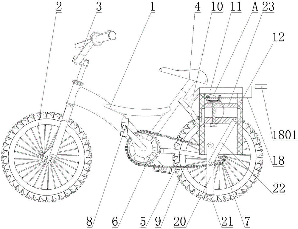
Fig. 1 is a schematic structural view of a leg link device of a toy bicycle according to the present invention.
Fig. 2 is an enlarged view of a portion a of fig. 1.
Reference numerals: 1. a frame; 2. a front wheel; 3. a handle head; 4. a vehicle seat; 5. a rear wheel; 6. a first sprocket; 7. a second sprocket; 8. pedaling; 9. a chain; 10. a connecting plate; 11. a support plate; 12. placing the cylinder; 1201. a chute; 13. a slide plate; 1301. a slider; 14. a screw rod; 15. a first gear; 16. a rotating shaft; 17. a second gear; 18. a crank; 1801. an anti-slip sleeve; 19. a limiting block; 20. supporting legs; 21. a universal wheel; 22. a connecting rod; 23. and (7) mounting the plate.
Detailed Description
In order to make the objects, technical solutions and advantages of the present invention more apparent, the present invention will be described in detail with reference to the accompanying drawings. It should be understood that the description is intended to be illustrative only and is not intended to limit the scope of the present invention. Moreover, in the following description, descriptions of well-known structures and techniques are omitted so as to not unnecessarily obscure the concepts of the present invention.
As shown in fig. 1-2, the utility model provides a leg link device of a toy bicycle, which comprises a frame 1, a chain 9 and a supporting component;
the front part of the frame 1 is provided with a handle head 3; a saddle 4 is arranged in the middle of the frame 1; the bottom of the frame 1 is rotatably provided with a front wheel 2, and the front wheel 2 is positioned below the handle head 3; a first chain wheel 6 is arranged in the middle of the frame 1; a second chain wheel 7 is arranged at the rear part of the frame, and the second chain wheel 7 is in transmission connection with the first chain wheel 6 through a chain 9; the second chain wheel 7 is provided with a rear wheel 5; the first chain wheel 6 is provided with a pedal 8; the rear part of the frame 1 is provided with a connecting plate 10, and the connecting plate 10 is positioned above the rear wheel 5; a support plate 11 is arranged on one transverse side of the connecting plate 10, and the support plate 11 is positioned above the rear wheel 5;
the support components are provided with two groups, the two groups of support components are respectively arranged at the longitudinal two sides of the support plate 11, the support plate comprises a placing barrel 12, a sliding plate 13, a screw rod 14, a first gear 15, a rotating shaft 16, a second gear 17, support legs 20, universal wheels 21, a connecting rod 22 and a mounting plate 23, the placing barrel 12 is arranged at the longitudinal two sides of the support plate 11, the mounting plate 23 is arranged on the inner wall of the placing barrel 12, the sliding plate 13 is arranged on the inner wall of the placing barrel 12 in a sliding way, the sliding plate 13 is positioned below the mounting plate 23, the screw rod 14 is arranged on the mounting plate 23 in a rotating way, the screw rod 14 penetrates through the mounting plate 23, the screw rod 14 is in threaded connection with the sliding plate 13, the first gear 15 is arranged at the upper end of the screw rod 14, the first gear 15 is positioned above the mounting plate 23, the rotating shaft 16 is arranged on the inner wall of the placing barrel 12 in a rotating way, the rotating shaft 16 is positioned above the mounting plate 23, the rotating shaft 16 penetrates through one lateral side of the placing barrel 12, the second gear 17 is arranged on the rotating shaft 16, the second gear 17 is meshed with the first gear 15, the supporting leg 20 is rotatably arranged on the inner wall of the placing barrel 12, the supporting leg 20 is positioned below the sliding plate 13, the universal wheel 21 is arranged at the bottom of the supporting leg 20, and two ends of the connecting rod 22 are respectively rotatably connected with the sliding plate 13 and the supporting leg 20.
In an alternative embodiment, the first gear 15 and the second gear 17 are hypoid gears, and the first gear 15 and the second gear 17 are perpendicular in axis, so that stability of the first gear 15 and the second gear 17 during transmission can be guaranteed.
In an alternative embodiment, the inner walls of the placing cylinder 12 at both lateral sides are provided with sliding grooves 1201; the horizontal both sides of slide 13 all are provided with slider 1301, slider 1301 with place a section of thick bamboo 12 sliding connection, slider 1301 is located the spout 1201, slides in the spout 1201 through setting up slider 1301, can guarantee slide stability of slide 13 on placing a section of thick bamboo 12 inner wall.
In an optional embodiment, the sliding groove 1201 is a T-shaped groove structure, the sliding block 1301 is a T-shaped block structure matched with the sliding groove 1201, and the T-shaped sliding block 1301 is matched with the T-shaped sliding groove 1201, so that guiding and limiting can be achieved.
In an alternative embodiment, the device further comprises a crank 18, the crank 18 is arranged at one end of the rotating shaft 16, which is positioned at the outer side of the placing barrel 12, the crank 18 is in a Z-shaped structure, and the rotating shaft 16 is controlled to rotate through the crank 18, so that the device is more convenient and simpler.
In an alternative embodiment, an anti-slip sleeve 1801 is disposed at an end of the crank 18 away from the rotating shaft 16, and anti-slip threads are disposed on the anti-slip sleeve 1801, so that the crank 18 can be prevented from slipping when being cranked by hand by providing the anti-slip sleeve 1801.
In an optional embodiment, the sliding device further comprises a limiting block 19, the limiting block 19 is arranged at the lower end of the screw rod 14, and the limiting block 19 is located above the supporting leg 20 to ensure that the sliding plate 13 cannot slip off the screw rod 14.
When the utility model is used, parents can put down two universal wheels 21 if they do not have time to look after children, so that children can learn to ride by themselves, if children are older and want children to know balance by themselves, the parents rotate the crank 18, the crank 18 drives the rotating shaft 16 to rotate, the rotating shaft 16 drives the second gear 17 to rotate, the second gear 17 drives the first gear 15 to rotate, the first gear 15 drives the screw rod 14 to rotate, the screw rod 14 drives the sliding plate 13 to ascend, the sliding plate 13 drives the connecting rod 22 to ascend, the connecting rod 22 drives the supporting leg 20 to ascend, the supporting leg 20 drives the universal wheels 21 to ascend, and the universal wheels 21 are collected into the placing barrel 12, so that children can know balance by themselves; meanwhile, parents can also rotate the crank 18 and retract the universal wheels 21 in the riding process of children, so that the bicycle can be more suitable for children to learn, and is high in flexibility and practicability in use.
It is to be understood that the above-described embodiments of the present invention are merely illustrative of or explaining the principles of the invention and are not to be construed as limiting the invention. Therefore, any modification, equivalent replacement, improvement and the like made without departing from the spirit and scope of the present invention should be included in the protection scope of the present invention. Further, it is intended that the appended claims cover all such variations and modifications as fall within the scope and boundaries of the appended claims or the equivalents of such scope and boundaries.