CN213730450U - Numerical control machining rotation angle table - Google Patents
Numerical control machining rotation angle table Download PDFInfo
- Publication number
- CN213730450U CN213730450U CN202021254874.7U CN202021254874U CN213730450U CN 213730450 U CN213730450 U CN 213730450U CN 202021254874 U CN202021254874 U CN 202021254874U CN 213730450 U CN213730450 U CN 213730450U
- Authority
- CN
- China
- Prior art keywords
- workpiece
- rotation angle
- rod
- wall
- sleeve
- Prior art date
- Legal status (The legal status is an assumption and is not a legal conclusion. Google has not performed a legal analysis and makes no representation as to the accuracy of the status listed.)
- Active
Links
- 238000003754 machining Methods 0.000 title claims abstract description 22
- 230000000670 limiting effect Effects 0.000 claims abstract description 45
- 238000010586 diagram Methods 0.000 description 4
- 230000000694 effects Effects 0.000 description 4
- 244000309464 bull Species 0.000 description 3
- 230000001360 synchronised effect Effects 0.000 description 3
- 238000005516 engineering process Methods 0.000 description 2
- 239000002184 metal Substances 0.000 description 2
- 238000000034 method Methods 0.000 description 2
- 230000009286 beneficial effect Effects 0.000 description 1
- 230000006835 compression Effects 0.000 description 1
- 238000007906 compression Methods 0.000 description 1
- 238000010276 construction Methods 0.000 description 1
- 238000005553 drilling Methods 0.000 description 1
- 238000003801 milling Methods 0.000 description 1
Images


Landscapes
- Machine Tool Units (AREA)
Abstract
The utility model discloses a numerical control machining rotation angle table, which comprises a bottom plate, wherein the left side of the top of the bottom plate is fixedly connected with a support frame, the top of the support frame is fixedly connected with a connecting disc, the outer wall of the connecting disc is rotatably connected with a driven wheel, the right side of the top of the bottom plate is provided with a motor, a belt is arranged between the driven wheel and the shaft part of the motor, the inner part of the connecting disc is rotatably connected with a rotating rod, the bottom of the rotating rod is provided with a second helical gear, the upper end of the limiting rod moves towards a workpiece at the moment due to the lever principle, thereby compressing a spring is compressed, thereby clamping the workpiece, the surface of the workpiece is prevented from being damaged by arranging a positioning head with a rubber structure, the workpiece is prevented from sliding by arranging anti-skid lines, the limiting effect is improved by arranging three groups of limiting rods which are arranged in a triangle, the workpiece is prevented from loosening during machining due to the manual pressing and fixing of the workpiece, thereby affecting the machining accuracy.
Description
Technical Field
The utility model relates to an auto-parts processing technology field specifically is a numerical control processing rotation angle platform.
Background
The numerical control machining rotation angle table is a machine tool accessory with a rotatable table top and used for clamping automobile workpieces and realizing rotation and indexing positioning. The rotary table can be divided into a general rotary table and a precise rotary table according to different functions, is an important accessory of a boring machine, a drilling machine, a milling machine, an slotting machine and the like, is used for processing holes, grooves and inclined planes with indexing requirements, and can process arc surfaces, arc grooves and the like by rotating the working table during processing. The universal rotary table is divided into a horizontal rotary table, a vertical and horizontal rotary table and a universal rotary table according to different structures.
Chinese patent discloses a numerical control processing rotation angle platform (grant publication No. CN 201821627304.0), this patent technique can be equipped with portable reference column, expansion bracket and adjustable fixed column, be convenient for adjust the height of revolving stage, can conveniently remove the revolving stage, can control sheet metal component processing position, can also be according to the size of sheet metal component, fix through the reference column, bring better use prospect, but current numerical control processing rotation angle platform adds the fixed work piece of the general needs manpower of man-hour, lead to adding easily that the work piece takes place not hard up man-hour, thereby influence the machining precision, and current numerical control processing rotation angle platform can not adjust the revolving stage height when rotatory, can not satisfy the use of co-altitude, bring inconvenience for the user. Therefore, a numerical control machining rotation angle table is provided by the technical personnel in the field to solve the problems in the background technology.
SUMMERY OF THE UTILITY MODEL
An object of the utility model is to provide a numerical control processing rotation angle platform to the fixed work piece of the general needs manpower is being added man-hour in the but current numerical control processing rotation angle platform that proposes in solving above-mentioned background art, leads to easily adding man-hour work piece emergence not hard up, thereby influences the machining precision, and current numerical control processing rotation angle platform can not adjust the revolving stage height when rotatory, can not satisfy the not use of co-altitude, the problem of inconvenience is brought for the user.
In order to achieve the above object, the utility model provides a following technical scheme:
a support frame is fixedly connected to the left side of the top of the bottom plate, a connecting disc is fixedly connected to the top of the support frame, a driven wheel is rotatably connected to the outer wall of the connecting disc, a motor is arranged on the right side of the top of the bottom plate, a belt is arranged between the driven wheel and a motor shaft portion, a rotating rod is rotatably connected to the interior of the connecting disc, a second bevel gear is arranged at the bottom of the rotating rod, a rocker is arranged on the left side wall of the support frame, a first bevel gear is arranged at the position, opposite to the second bevel gear, of the right end of the rocker, a sleeve is in threaded connection with the top of the rotating rod, a connecting frame is arranged at the top of the connecting disc, opposite to the outer wall of the sleeve, a rotating table is rotatably connected to the top of the sleeve, a telescopic rod is arranged between the bottom of the rotating table and the top of the driven wheel, and a limiting shell is fixedly connected to the top of the rotating table, the inside of spacing casing rotates and is connected with the flange, the upside position that the inside of spacing casing is located the flange is provided with puts the thing platform, the top of putting the thing platform is provided with the machined part, be provided with the regulation pole between the bottom of flange and the revolving stage, the outer wall swing joint of spacing casing has the gag lever post, be provided with the connecting rod between the downside and the flange of the one side of being close to spacing casing of gag lever post.
As a further aspect of the present invention: the sleeve is the cuboid structure, just sleeve and link inner wall sliding connection, through the sleeve that sets up the cuboid structure, when the bull stick rotates, the sleeve does not follow synchronous rotation, because the screw thread effect, sleeve rebound this moment to drive revolving stage rebound.
As a further aspect of the present invention: and a spring is arranged between the upper side of one side of the limiting rod, which is close to the limiting shell, and the outer wall of the limiting shell.
As a further aspect of the present invention: the outer wall of the convex disc is provided with a convex block relative to the connecting rod, and the connecting rod is driven to be in contact with the outer wall of the convex block when the convex disc rotates anticlockwise through the arrangement of the convex block, so that the connecting rod is pushed to move outwards, outwards force is applied to the bottom of the limiting rod, and the upper end of the limiting rod moves towards the direction of a workpiece at the moment due to the lever principle, so that the limiting function of the workpiece is realized.
As a further aspect of the present invention: the limiting rods are provided with three groups, the three groups of limiting rods are arranged in a triangular mode, and limiting effects are improved by arranging the three groups of limiting rods arranged in the triangular mode.
As a further aspect of the present invention: the locating head is arranged at the top of one side, close to the workpiece, of the limiting rod and is of a rubber structure, anti-slip lines are arranged on the surface of the locating head, the surface of the workpiece is prevented from being damaged through the locating head with the rubber structure, sliding is prevented through the anti-slip lines, and the limiting effect is improved.
Compared with the prior art, the beneficial effects of the utility model are that:
1. place the machined part in the upper end of putting the thing platform, the regulation pole rotates right, thereby it counter-clockwise turning to drive the protruding dish, thereby drive connecting rod and the contact of protruding piece outer wall, thereby promote the connecting rod and outwards remove, thereby exert outside power to the gag lever post bottom, because lever principle, the gag lever post upper end removes to the machined part direction this moment, thereby compression spring, thereby press from both sides tight machined part, through the location head that sets up rubber construction, prevent to harm the machined part surface, prevent through setting up anti-skidding line that the machined part slides, through setting up the gag lever post that three groups are triangle-shaped range, improve spacing effect, prevent that the manpower from pressing down fixed machined part and lead to adding man-hour machined part emergence not hard up, thereby influence the phenomenon of machining precision.
2. When the machined part is required to rotate, the motor is started, the driven wheel is driven to rotate through the belt, so that the telescopic rod is driven to rotate, the rotating platform is driven to rotate, and the machined part is rotated.
3. When the height of machined part is adjusted to needs, through rotating the rocker to drive first helical gear and rotate, thereby drive the rotation of second helical gear, thereby drive the bull stick and rotate, through the sleeve that sets up the cuboid structure, when the bull stick rotates, the sleeve does not follow synchronous rotation, because the screw thread effect, sleeve rebound this moment, thereby drive revolving stage rebound, thereby adjust the height of machined part.
Drawings
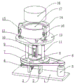
Fig. 1 is a schematic structural diagram of a numerical control machining rotation angle table.
Fig. 2 is a schematic front view of a numerical control machining rotation angle table.
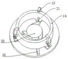
Fig. 3 is a schematic structural diagram of a convex disc in a numerical control machining rotation angle table.
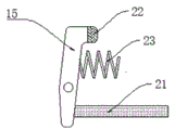
Fig. 4 is a schematic structural diagram of a limiting rod in a numerical control machining rotation angle table.
FIG. 5 is a schematic structural diagram of a sleeve in a numerical control machining rotation angle table
In the figure: 1. a base plate; 2. a support frame; 3. a first helical gear; 4. a rocker; 5. a motor; 6. a belt; 7. a driven wheel; 8. a connecting disc; 9. a rotating rod; 10. a sleeve; 11. a telescopic rod; 12. a connecting frame; 13. a rotating table; 14. a limiting shell; 15. a limiting rod; 16. adjusting a rod; 17. a placing table; 18. processing a workpiece; 19. a second helical gear; 20. a convex disc; 21. a connecting rod; 22. positioning the head; 23. a spring.
Detailed Description
The technical solutions in the embodiments of the present invention will be described clearly and completely with reference to the accompanying drawings in the embodiments of the present invention, and it is obvious that the described embodiments are only some embodiments of the present invention, not all embodiments. Based on the embodiments in the present invention, all other embodiments obtained by a person skilled in the art without creative work belong to the protection scope of the present invention.
Referring to fig. 1-5, in the embodiment of the present invention, a numerical control machining rotation angle table comprises a bottom plate 1, a supporting frame 2 is fixedly connected to the left side of the top of the bottom plate 1, a connecting disc 8 is fixedly connected to the top of the supporting frame 2, a driven wheel 7 is rotatably connected to the outer wall of the connecting disc 8, a motor 5 is arranged on the right side of the top of the bottom plate 1, a belt 6 is arranged between the driven wheel 7 and the shaft portion of the motor 5, a rotating rod 9 is rotatably connected to the inside of the connecting disc 8, a second helical gear 19 is arranged at the bottom of the rotating rod 9, a rocker 4 is arranged on the left side wall of the supporting frame 2, a first helical gear 3 is arranged at the right end of the rocker 4 corresponding to the second helical gear 19, a sleeve 10 is in threaded connection with the top of the rotating rod 9, a connecting frame 12 is arranged at the top of the connecting disc 8 corresponding to the outer wall of the sleeve 10, the sleeve 10 is of a rectangular structure, and the sleeve 10 is slidably connected to the inner wall of the connecting frame 12, by arranging the sleeve 10 with a cuboid structure, when the rotating rod 9 rotates, the sleeve 10 does not rotate synchronously with the rotating rod 9, due to the action of screw threads, the sleeve 10 moves upwards to drive the rotating platform 13 to move upwards, the top of the sleeve 10 is connected with the rotating platform 13 in a rotating way, an expansion rod 11 is arranged between the bottom of the rotating platform 13 and the top of the driven wheel 7, the top of the rotating platform 13 is fixedly connected with a limiting shell 14, a convex disc 20 is connected in the limiting shell 14 in a rotating way, an object placing platform 17 is arranged in the limiting shell 14 and at the upper side of the convex disc 20, a workpiece 18 is arranged at the top of the object placing platform 17, an adjusting rod 16 is arranged between the bottom of the convex disc 20 and the rotating platform 13, a limiting rod 15 is movably connected with the outer wall of the limiting shell 14, a spring 23 is arranged between the upper side of the limiting rod 15, which is close to one side of the limiting shell 14, and the convex disc 20, and a connecting rod 21 is arranged between the lower side of the limiting rod 15, which is close to one side of the limiting shell 14, the outer wall of the convex disc 20 is provided with a convex block at a position corresponding to the connecting rod 21, the connecting rod 21 is driven to contact with the outer wall of the convex block when the convex disc 20 rotates anticlockwise through the arrangement of the convex block, thereby pushing the connecting rod 21 to move outwards, thereby applying an outward force to the bottom of the limiting rod 15, because of the lever principle, the upper end of the limiting rod 15 moves towards the workpiece 18 at the moment to realize the limiting function of the workpiece 18, three groups of limiting rods 15 are arranged, the three groups of limiting rods 15 are arranged in a triangle, the limiting effect is improved by arranging three groups of limiting rods 15 which are arranged in a triangular shape, the top of one side of the limiting rod 15 close to the workpiece 18 is provided with a positioning head 22, the positioning head 22 is of a rubber structure, the surface of the positioning head is provided with anti-skid lines, the surface of the workpiece 18 is prevented from being damaged by arranging the positioning head 22 with a rubber structure, and the sliding is prevented by arranging the anti-sliding lines, so that the limiting effect is improved.
The utility model discloses a theory of operation is:
when the utility model is used, the workpiece 18 is placed at the upper end of the object placing table 17, the adjusting rod 16 is rotated rightwards, so that the convex disc 20 is driven to rotate anticlockwise, the connecting rod 21 is driven to contact with the outer wall of the convex block, the connecting rod 21 is pushed to move outwards, so that an outward force is applied to the bottom of the limiting rod 15, due to the lever principle, the upper end of the limiting rod 15 moves towards the workpiece 18, so that the spring 23 is compressed, the workpiece 18 is clamped, the surface of the workpiece 18 is prevented from being damaged by arranging the positioning head 22 with a rubber structure, the workpiece 18 is prevented from sliding by arranging the anti-sliding lines, the limiting effect is improved by arranging three groups of the limiting rods 15 which are arranged in a triangular shape, the phenomenon that the workpiece 18 is loosened during processing due to the fact that the workpiece 18 is pressed and fixed by manpower, so that the processing precision is influenced is avoided, when the workpiece 18 is required to rotate, the motor 5 is started, drive through belt 6 and rotate from driving wheel 7, thereby drive telescopic link 11 and rotate, thereby drive revolving stage 13 and rotate, the realization is to the rotation of machined part 18, when the height of machined part 18 is adjusted to needs, through rotating rocker 4, thereby drive first helical gear 13 and rotate, thereby drive second helical gear 19 and rotate, thereby drive revolving stage 9 and rotate, sleeve 10 through setting up the cuboid structure, when revolving stage 9 rotates, sleeve 10 does not follow 9 synchronous rotations, because the screw thread effect, sleeve 10 moves up this moment, thereby drive revolving stage 13 rebound, thereby adjust the height of machined part 18.
The above, only be the concrete implementation of the preferred embodiment of the present invention, but the protection scope of the present invention is not limited thereto, and any person skilled in the art is in the technical scope of the present invention, according to the technical solution of the present invention and the utility model, the concept of which is equivalent to replace or change, should be covered within the protection scope of the present invention.
Claims (6)
1. The numerical control machining rotation angle table comprises a bottom plate (1) and is characterized in that a support frame (2) is fixedly connected to the left side of the top of the bottom plate (1), a connecting disc (8) is fixedly connected to the top of the support frame (2), a driven wheel (7) is rotatably connected to the outer wall of the connecting disc (8), a motor (5) is arranged on the right side of the top of the bottom plate (1), a belt (6) is arranged between the driven wheel (7) and the shaft portion of the motor (5), a rotating rod (9) is rotatably connected to the inside of the connecting disc (8), a second helical gear (19) is arranged at the bottom of the rotating rod (9), a rocker (4) is arranged on the left side wall of the support frame (2), a first helical gear (3) is arranged at the position, opposite to the second helical gear (19), of the right end of the rocker (4), and a sleeve (10) is in threaded connection with the top of the rotating rod (9), the top of the connecting disc (8) is provided with a connecting frame (12) relative to the outer wall of the sleeve (10), the top of the sleeve (10) is rotationally connected with a rotating platform (13), a telescopic rod (11) is arranged between the bottom of the rotating platform (13) and the top of the driven wheel (7), the top of the rotating platform (13) is fixedly connected with a limiting shell (14), the inside of the limiting shell (14) is rotatably connected with a convex disc (20), an object placing table (17) is arranged at the upper side of the convex disc (20) in the limiting shell (14), a workpiece (18) is arranged at the top of the object placing table (17), an adjusting rod (16) is arranged between the bottom of the convex disc (20) and the rotating table (13), the outer wall swing joint of spacing casing (14) has gag lever post (15), be provided with connecting rod (21) between the downside and flange (20) of the one side of gag lever post (15) that is close to spacing casing (14).
2. The numerical control machining rotation angle table according to claim 1, characterized in that the sleeve (10) is of a rectangular parallelepiped structure, and the sleeve (10) is slidably connected with the inner wall of the connecting frame (12).
3. A numerically controlled machining rotation angle table according to claim 1, characterized in that a spring (23) is provided between the upper side of the limit rod (15) close to the limit housing (14) and the outer wall of the limit housing (14).
4. The numerical control machining rotation angle table according to claim 1, characterized in that the outer wall of the convex disc (20) is provided with a convex block at a position opposite to the connecting rod (21).
5. A numerically controlled machining rotation angle table according to claim 1, characterized in that said stop rods (15) are provided in three sets, said stop rods (15) of three sets being arranged in a triangle.
6. The numerical control machining rotation angle table according to claim 1, characterized in that a positioning head (22) is arranged at the top of one side of the limiting rod (15) close to the workpiece (18), the positioning head (22) is of a rubber structure, and the surface of the positioning head is provided with anti-skid lines.
Priority Applications (1)
| Application Number | Priority Date | Filing Date | Title |
|---|---|---|---|
| CN202021254874.7U CN213730450U (en) | 2020-07-01 | 2020-07-01 | Numerical control machining rotation angle table |
Applications Claiming Priority (1)
| Application Number | Priority Date | Filing Date | Title |
|---|---|---|---|
| CN202021254874.7U CN213730450U (en) | 2020-07-01 | 2020-07-01 | Numerical control machining rotation angle table |
Publications (1)
| Publication Number | Publication Date |
|---|---|
| CN213730450U true CN213730450U (en) | 2021-07-20 |
Family
ID=76814631
Family Applications (1)
| Application Number | Title | Priority Date | Filing Date |
|---|---|---|---|
| CN202021254874.7U Active CN213730450U (en) | 2020-07-01 | 2020-07-01 | Numerical control machining rotation angle table |
Country Status (1)
| Country | Link |
|---|---|
| CN (1) | CN213730450U (en) |
Cited By (2)
| Publication number | Priority date | Publication date | Assignee | Title |
|---|---|---|---|---|
| CN114770143A (en) * | 2022-06-16 | 2022-07-22 | 江苏宏达数控科技股份有限公司 | Gantry type numerical control machining tool |
| CN114905219A (en) * | 2022-05-11 | 2022-08-16 | 京信射频技术(广州)有限公司 | Auxiliary tool for welding communication device |
-
2020
- 2020-07-01 CN CN202021254874.7U patent/CN213730450U/en active Active
Cited By (4)
| Publication number | Priority date | Publication date | Assignee | Title |
|---|---|---|---|---|
| CN114905219A (en) * | 2022-05-11 | 2022-08-16 | 京信射频技术(广州)有限公司 | Auxiliary tool for welding communication device |
| CN114905219B (en) * | 2022-05-11 | 2023-12-22 | 京信射频技术(广州)有限公司 | Be used for communication device welded auxiliary fixtures |
| CN114770143A (en) * | 2022-06-16 | 2022-07-22 | 江苏宏达数控科技股份有限公司 | Gantry type numerical control machining tool |
| CN114770143B (en) * | 2022-06-16 | 2022-09-27 | 江苏宏达数控科技股份有限公司 | Gantry type numerical control machining tool |
Similar Documents
| Publication | Publication Date | Title |
|---|---|---|
| CN211439540U (en) | Polishing workbench fixing and clamping equipment | |
| CN216882780U (en) | Oil groove machining center for machining bearing bush oil line | |
| CN214445706U (en) | Machining workbench convenient to clamp | |
| CN211029341U (en) | Outside grinding device of stainless steel stamping workpiece | |
| CN215200352U (en) | Clamping device of full-automatic welding machine | |
| CN219561500U (en) | Single-head milling machine for front bearing shaft sleeve production | |
| CN220805756U (en) | Tapping machine positioner for workpiece machining | |
| CN215393902U (en) | Four-axis anchor clamps of convenient debugging | |
| CN219925293U (en) | Clamping tool convenient to adjust | |
| CN207840198U (en) | Tooling for radial drilling machine workbench | |
| CN214024640U (en) | Clamping device for machining precision machinery parts | |
| CN108838737A (en) | A kind of lathe of electromechanical integration processing | |
| CN215433182U (en) | Chamfering device for aluminum part machining | |
| CN221158665U (en) | Manual electric drill with high drilling precision | |
| CN213917506U (en) | Precision machine tool for machining anti-deviation grinding tool | |
| CN213438661U (en) | Clamping device of grinding head of numerical control cylindrical grinding machine | |
| CN213592455U (en) | Grinding device is used in production of indoor lamp shade | |
| CN221159645U (en) | Surface grinding machine positioning equipment for metal piece machining | |
| CN211889949U (en) | Fixing device is used in cutting of polisher protection casing | |
| CN211465990U (en) | Workpiece fixing structure for grinding machine | |
| CN214109907U (en) | Grinding device is used in sheet metal processing | |
| CN220637024U (en) | Two-way centre gripping frock of engine flywheel processing | |
| CN221232229U (en) | Corner polishing device for wood board production and processing | |
| CN220127953U (en) | High-efficient high accuracy welded fastening frock | |
| CN217750731U (en) | Circumference grinding equipment for motor end cover |
Legal Events
| Date | Code | Title | Description |
|---|---|---|---|
| GR01 | Patent grant | ||
| GR01 | Patent grant |