CN213728100U - Cleaning device for automobile gear - Google Patents
Cleaning device for automobile gear Download PDFInfo
- Publication number
- CN213728100U CN213728100U CN202022357890.5U CN202022357890U CN213728100U CN 213728100 U CN213728100 U CN 213728100U CN 202022357890 U CN202022357890 U CN 202022357890U CN 213728100 U CN213728100 U CN 213728100U
- Authority
- CN
- China
- Prior art keywords
- welded
- automobile gear
- mounting plate
- cleaning device
- tank body
- Prior art date
- Legal status (The legal status is an assumption and is not a legal conclusion. Google has not performed a legal analysis and makes no representation as to the accuracy of the status listed.)
- Active
Links
- 238000004140 cleaning Methods 0.000 title claims abstract description 17
- XLYOFNOQVPJJNP-UHFFFAOYSA-N water Substances O XLYOFNOQVPJJNP-UHFFFAOYSA-N 0.000 claims abstract description 15
- 238000001125 extrusion Methods 0.000 claims abstract description 12
- 238000003466 welding Methods 0.000 claims description 7
- 210000005056 cell body Anatomy 0.000 claims description 6
- 230000000149 penetrating effect Effects 0.000 abstract description 6
- 239000007921 spray Substances 0.000 description 5
- 239000012535 impurity Substances 0.000 description 4
- 230000005540 biological transmission Effects 0.000 description 2
- 239000007858 starting material Substances 0.000 description 2
- 230000009286 beneficial effect Effects 0.000 description 1
- 238000010586 diagram Methods 0.000 description 1
- 230000000694 effects Effects 0.000 description 1
- 238000005516 engineering process Methods 0.000 description 1
- 238000009434 installation Methods 0.000 description 1
- 238000003754 machining Methods 0.000 description 1
- 238000000034 method Methods 0.000 description 1
- 238000005406 washing Methods 0.000 description 1
Images


Landscapes
- Cleaning In General (AREA)
Abstract
The utility model relates to the technical field of automobile gear cleaning, in particular to a cleaning device for automobile gears, a first mounting plate is welded on one side in a tank body, a casing is welded on the lower portion of the first mounting plate, a motor is installed on the lower portion of the first mounting plate in the casing, a driving wheel is welded on one end of a main shaft in a penetrating manner, a plurality of second mounting plates are welded on one side in the tank body, a shaft sleeve is welded on the upper portion of each second mounting plate, a rotating shaft is sleeved in each shaft sleeve, two driven wheels are welded on one end of the rotating shaft in a penetrating manner, clamping grooves are formed in the upper portions of the main shaft and the rotating shaft, clamping blocks matched with the clamping grooves are clamped in the clamping grooves, a baffle is welded on one end of each clamping block, a fixed rod is welded on the upper portion of the baffle, an extrusion layer is adhered on the outer surface of the fixed rod, pull rings are welded on the upper portions of the fixed rods, a plurality of connecting pipes are welded on one side of the tank body, and a total water pipe is welded between one ends of the plurality of the connecting pipes, the utility model discloses, can be convenient clear up the concave position of automobile gear side.
Description
Technical Field
The utility model relates to an automobile gear clearance technical field especially relates to a cleaning device for automobile gear.
Background
The gear is a main basic transmission element in the automobile industry, generally, each automobile is provided with 18-30 tooth parts, in recent years, the gear technology is rapidly developed, and the development trend can be summarized as high bearing capacity, high tooth surface hardness, high precision, high speed, high reliability and high transmission efficiency. In the process of machining the gear, the gear is required to be cleaned of impurities stuck to the surface, the impurities are usually cleaned manually, but the impurities on the concave surfaces of the teeth on the side surfaces of the gear are usually inconvenient to clean.
SUMMERY OF THE UTILITY MODEL
The utility model aims at solving the shortcoming of inconvenient clearance of existing among the prior art, and the cleaning device for automobile gear who provides.
In order to achieve the above purpose, the utility model adopts the following technical scheme:
designing a cleaning device for an automobile gear, wherein a first mounting plate is welded on one side in a groove body, a shell is welded below the first mounting plate, a motor is arranged below the first mounting plate and positioned in the shell, the input end of the motor is connected with an external power supply, the output end of the motor is connected with a main shaft through a coupler, one end of the main shaft is in through welding with a driving wheel, a plurality of second mounting plates are welded on one side in the groove body, shaft sleeves are welded above the second mounting plates, rotating shafts are sleeved in the shaft sleeves, one ends of the rotating shafts are in through welding with two driven wheels, clamping grooves are formed above the main shaft and the rotating shafts, clamping blocks matched with the clamping grooves are clamped in the clamping grooves, baffles are welded at one ends of the clamping blocks, fixing rods are welded above the baffles, extrusion layers are adhered to the outer surfaces of the fixing rods, and a plurality of flange blocks are integrally formed on the surfaces of the extrusion layers, the utility model discloses a valve, including dead lever, cell body, valve, connecting pipe, valve, the dead lever top all welds there is the pull ring, the welding has a plurality of connecting pipe, a plurality of to run through on one side of the cell body the welding has water main between the connecting pipe one end, install the valve in water main one end, the connecting pipe is located the cell body one end side and has cup jointed a plurality of shower nozzle.
Preferably, telescopic cylinder has been welded to one side in the cell body, telescopic cylinder's one end's piston rod has the fixed plate, there is the connecting plate fixed plate 0 one side through the mounting screw, the welding of connecting plate one side has a plurality of brush body.
Preferably, a first belt is sleeved between the driving wheel on the main shaft and one driven wheel on the adjacent rotating shaft.
Preferably, a second belt is sleeved between two symmetrical driven wheels on two adjacent rotating shafts.
Preferably, the bottom end of one side of the groove body is sleeved with a drain pipe, and a door body is rotatably arranged on one side of the groove body.
The utility model provides a pair of cleaning device for automobile gear, beneficial effect lies in: this design mainly drives a plurality of spacing automobile gear who places of stack through rotary mechanism and rotates and wash the side, makes the concave recess of automobile gear side also can be convenient by the clean up.
Drawings
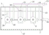
Fig. 1 is a schematic structural view of a cleaning device for an automobile gear according to the present invention;
fig. 2 is a schematic top view of the cleaning device for the automobile gear according to the present invention;
fig. 3 is the utility model provides a structural schematic diagram of main shaft of cleaning device for automobile gear.
In the figure: the device comprises a tank body 1, a first mounting plate 2, a machine shell 3, a motor 4, a main shaft 5, a second mounting plate 6, a shaft sleeve 7, a rotating shaft 8, a driven wheel 9, a first belt 10, a second belt 11, a baffle 12, an extrusion layer 13, a flange block 14, a pull ring 15, a fixed rod 16, a driving wheel 17, a connecting pipe 18, a water main pipe 19, a spray head 20, a telescopic cylinder 21, a connecting plate 22, a valve 23, a brush body 24, a fixture block 25, a drain pipe 26, a door body 27, an automobile gear 28, a clamping groove 29 and a fixing plate 30.
Detailed Description
The technical solutions in the embodiments of the present invention will be described clearly and completely with reference to the accompanying drawings in the embodiments of the present invention, and it is obvious that the described embodiments are only some embodiments of the present invention, not all embodiments.
Example 1
Referring to fig. 1-3, a cleaning device for an automobile gear, which comprises a tank body 1, and is characterized in that a first mounting plate 2 is welded on one side in the tank body 1, a machine shell 3 is welded on the lower portion of the first mounting plate 2, a motor 4 is installed below the first mounting plate 2 and in the machine shell 3, the input end of the motor 4 is connected with an external power supply, the output end of the motor 4 is connected with a main shaft 5 through a coupler, one end of the main shaft 5 is welded with a driving wheel 17 in a penetrating manner, a plurality of second mounting plates 6 are welded on one side in the tank body 1, the upper surfaces of the first mounting plate 2 and the second mounting plates 6 are both arc-shaped structures, so that water after washing can better fall down, shaft sleeves 7 are welded on the upper portions of the second mounting plates 6, rotating shafts 8 are sleeved in the shaft sleeves 7, one ends of the rotating shafts 8 are both welded with two driven wheels 9 in a penetrating manner, a first belt 10 is sleeved between the driving wheel 17 on the main shaft 5 and one of the driven wheels 9 on the adjacent rotating shafts 8, all there is the second belt 11 between the follower 9 of two symmetries on two adjacent pivots 8, when starter motor 4, motor 4 will drive main shaft 5 and rotate, integrative action wheel 17 of installation on main shaft 5 will also rotate, it will drive the follower 9 on the pivot 8 that one end is connected to overlap on action wheel 17 and rotate to have first belt 10, it is this pivot 8 also will rotate, because all connect through second belt 11 between the follower 9 on each pivot 8, when starter motor 4, each pivot 8 will also rotate, the placing mechanism who makes connection on main shaft 5 and each pivot 8 can drive the auto gear 28 rotation of placing and clear up cleanly.
The clamping grooves 29 are respectively formed above the main shaft 5 and the rotating shaft 8, the clamping blocks 25 matched with the clamping grooves are respectively clamped in the clamping grooves 29, the clamping grooves 29 are matched with the clamping blocks 25, the baffle plates 12 are respectively welded at one ends of the clamping blocks 25, the fixed rods 16 are respectively welded above the baffle plates 12, the extrusion layers 13 are respectively adhered to the outer surfaces of the fixed rods 16, the plurality of flange blocks 14 are respectively and integrally formed on the surfaces of the extrusion layers 13, pull rings 15 are respectively welded above the fixed rods 16, the fixed rods 16 can be pulled upwards through the pull rings 15, the clamping blocks 25 welded below the baffle plates 12 are moved out of the clamping grooves 29 formed in the main shaft 5, the fixed rods 16 with the baffle plates 12 are disassembled, the automobile gears 28 can be conveniently placed, when the automobile gears 28 need to be placed, the plurality of automobile gears 28 can be stacked outside the fixed rods 16 in a penetrating manner, the extrusion layers 13 adhered outside the fixed rods 16 can be elastic rubber layers, and can play a certain extrusion limiting role on the automobile gears 28, the plurality of flange blocks 14 arranged on the extrusion layer 13 can increase the friction force of the extrusion layer 13 on the automobile gear 28, and the limiting and placing effects of the automobile gear 28 can be better.
One side of the tank body 1 is welded with a plurality of connecting pipes 18 in a penetrating way, a water main 19 is welded between one ends of the connecting pipes 18, one end of the water main 19 is connected to a water source, a pump body for water delivery is arranged on the water main 19, a valve 23 is arranged in one end of the water main 19, a plurality of spray heads 20 are sleeved on the side surface of one end of the connecting pipe 18 positioned in the tank body 1, a drain pipe 26 is sleeved at the bottom end of one side of the tank body 1, a door body 27 is rotatably arranged on one side of the tank body 1, the connecting pipes 18 with the plurality of spray heads 20 are respectively arranged on one side of the fixed rod 16, one spray head 20 corresponds to one gear 28 after the automobile gear 28 is placed in a limiting way, the automobile gear 28 which is placed in a limiting way can be rotated firstly, then the pump body is started and the valve 23 is opened, water flows into each connecting pipe 18 from the water main 19, and is sprayed out from each spray head 20 on each connecting pipe 18 to the corresponding automobile gear 28, the side of the automobile gear 28 is washed, so that the side concave part of the automobile gear 28 can be cleaned.
Example 2
Referring to fig. 3, as another preferred embodiment of the present invention, the only difference from embodiment 1 is that a telescopic cylinder 21 is welded on one side inside a tank body 1, a fixing plate 30 is welded on a piston rod at one end of the telescopic cylinder 21, a connecting plate 22 is installed on one side of the fixing plate 30 through screws, a plurality of brush bodies 24 are welded on one side of the connecting plate 22, the plurality of brush bodies 24 all correspond to an automobile gear 28 stacked on a fixing rod 16, when the automobile gear 28 is washed, the telescopic cylinder 21 can be started, the brush bodies 24 are driven by the telescopic cylinder 21 to be capable of contacting with one side surface of the automobile gear 28, and impurities adhered to the automobile gear 28 can be brushed and fallen by the brush bodies 24, so that the automobile gear 28 can be cleaned more quickly.
The above, only be the concrete implementation of the preferred embodiment of the present invention, but the protection scope of the present invention is not limited thereto, and any person skilled in the art is in the technical scope of the present invention, according to the technical solution of the present invention and the utility model, the concept of which is equivalent to replace or change, should be covered within the protection scope of the present invention.
Claims (5)
1. The cleaning device for the automobile gear comprises a tank body (1) and is characterized in that a first mounting plate (2) is welded on one side in the tank body (1), a casing (3) is welded on the lower portion of the first mounting plate (2), a motor (4) is installed in the casing (3) below the first mounting plate (2), the input end of the motor (4) is connected with an external power supply, the output end of the motor (4) is connected with a spindle (5) through a coupler, one end of the spindle (5) is penetratingly welded with a driving wheel (17), a plurality of second mounting plates (6) are welded on one side in the tank body (1), a shaft sleeve (7) is welded on the upper portion of each second mounting plate (6), a rotating shaft (8) is sleeved in each shaft sleeve (7), two driven wheels (9) are penetratingly welded on one end of each rotating shaft (8), and a clamping groove (29) is formed in the upper portions of each spindle (5), equal joint has assorted fixture block (25) with it in draw-in groove (29), baffle (12) have all been welded to fixture block (25) one end, dead lever (16) have all been welded to baffle (12) top, dead lever (16) surface all is stained with extrusion layer (13), extrusion layer (13) surface homogeneous phase integrated into one piece has a plurality of flange piece (14), pull ring (15) have all been welded to dead lever (16) top, cell body (1) one side through welding has a plurality of connecting pipe (18), a plurality of the welding has water main (19) between connecting pipe (18) one end, install valve (23) in water main (19) one end, connecting pipe (18) are located cell body (1) one end side and have cup jointed a plurality of shower nozzle (20).
2. The cleaning device for the automobile gear is characterized in that a telescopic cylinder (21) is welded on one side in the groove body (1), a fixing plate (30) is welded on a piston rod at one end of the telescopic cylinder (21), a connecting plate (22) is installed on one side of the fixing plate (30) through screws, and a plurality of brush bodies (24) are welded on one side of the connecting plate (22).
3. The cleaning device for the automobile gear according to claim 1, characterized in that a first belt (10) is sleeved between the driving wheel (17) on the main shaft (5) and one driven wheel (9) on the adjacent rotating shaft (8).
4. The cleaning device for the automobile gear according to claim 1, characterized in that a second belt (11) is sleeved between two symmetrical driven wheels (9) on two adjacent rotating shafts (8).
5. The cleaning device for the automobile gear is characterized in that a drain pipe (26) is sleeved at the bottom end of one side of the groove body (1), and a door body (27) is rotatably installed at one side of the groove body (1).
Priority Applications (1)
| Application Number | Priority Date | Filing Date | Title |
|---|---|---|---|
| CN202022357890.5U CN213728100U (en) | 2020-10-21 | 2020-10-21 | Cleaning device for automobile gear |
Applications Claiming Priority (1)
| Application Number | Priority Date | Filing Date | Title |
|---|---|---|---|
| CN202022357890.5U CN213728100U (en) | 2020-10-21 | 2020-10-21 | Cleaning device for automobile gear |
Publications (1)
| Publication Number | Publication Date |
|---|---|
| CN213728100U true CN213728100U (en) | 2021-07-20 |
Family
ID=76852455
Family Applications (1)
| Application Number | Title | Priority Date | Filing Date |
|---|---|---|---|
| CN202022357890.5U Active CN213728100U (en) | 2020-10-21 | 2020-10-21 | Cleaning device for automobile gear |
Country Status (1)
| Country | Link |
|---|---|
| CN (1) | CN213728100U (en) |
-
2020
- 2020-10-21 CN CN202022357890.5U patent/CN213728100U/en active Active
Similar Documents
| Publication | Publication Date | Title |
|---|---|---|
| CN213378240U (en) | An ultrasonic cleaning machine for cigarette rubber rollers | |
| CN219817368U (en) | Quick cleaning device of water conservancy pipeline | |
| CN106826865B (en) | bathtub cleaning robot | |
| CN202185433U (en) | Cylinder body overturn cleaning machine | |
| CN112222068A (en) | Cleaning device for automobile gear | |
| CN212733397U (en) | Novel petroleum machinery exploitation pipeline clearance device | |
| CN206560994U (en) | A kind of Digit Control Machine Tool observation window cleaning device | |
| CN221492082U (en) | Water purification membrane module belt cleaning device | |
| CN209753544U (en) | Machine parts belt cleaning device | |
| CN217857644U (en) | Circulating water washes into sand system for production of fine work mechanism sand | |
| CN116005789B (en) | Novel dredging device for urban water supply and drainage | |
| CN214108189U (en) | A chemical test tube cleaning device | |
| CN220126982U (en) | Single-station rotary spraying cleaning machine | |
| CN222942225U (en) | Sink cleaning device | |
| CN221442136U (en) | Vibrating machine | |
| CN219666160U (en) | Cold drawing grinding and washing device for seamless steel tube | |
| CN222412297U (en) | Self-cleaning mechanism of washing machine | |
| CN223159678U (en) | A mechanical parts washing machine | |
| CN222001040U (en) | Foundry goods self-cleaning device | |
| CN220111718U (en) | Cleaning device for crankshaft machining | |
| CN219733508U (en) | Automobile radiator convenient to wash | |
| CN216187848U (en) | A material loading cleaning device for production of external wall insulation board bonding glue | |
| CN218168017U (en) | Cleaning device for automobile maintenance tool | |
| CN110666576A (en) | Oil removing and cleaning device for shaft on machine tool | |
| CN222659576U (en) | A hydraulic cylinder inner wall cleaning device |
Legal Events
| Date | Code | Title | Description |
|---|---|---|---|
| GR01 | Patent grant | ||
| GR01 | Patent grant |