SUMMERY OF THE UTILITY MODEL
The utility model aims at providing a beer fermentation device of water solubility cannabidiol transports the yeast of upper strata and stirring in jar body bottom's mode through rotating helical blade with the deposit, and helical blade stall back most yeast can even deposit on helical blade gradually, makes jar internal difference in temperature diminish, is convenient for control the temperature.
The above technical purpose of the present invention can be achieved by the following technical solutions:
a beer fermentation device containing water-soluble cannabidiol comprises a hollow tank body with an opening at the upper end and a cover body used for sealing the opening end of the tank body, wherein the lower end of the tank body is in a reverse taper shape, a rotating shaft is vertically arranged in the tank body, the rotating shaft and the tank body are coaxial, a motor is vertically arranged in the center of the cover body, the upper end of the rotating shaft penetrates through the cover body and is connected with an output shaft of the motor, the rotating shaft and the cover body form rotating fit through a bearing, a helical blade is arranged on the circumferential side of one end of the rotating shaft in the tank body, the diameter of the helical blade at the reverse taper position of the tank body is gradually increased from bottom to top, and the outer diameter of the helical blade is half to two thirds;
the water cooling device comprises a tank body, a water inlet pipe, a water cooler, a controller and a water outlet pipe, wherein at least two cooling pipelines are arranged in the wall of the tank body, the at least two cooling pipelines are arranged side by side and are spirally arranged on the tank body, the lower ends of the at least two cooling pipelines penetrate through the tank body and are communicated with the water inlet pipe, one end of the water inlet pipe, which is far away from the tank body, is connected with the water cooler, the water outlet of the water cooler is communicated with the water inlet pipe, the water inlet of the water cooler is communicated with the water outlet pipe, the upper ends of the at least two cooling pipelines penetrate through the tank body and are communicated with the water outlet pipe;
the heat preservation is equipped with to the external of jar, be equipped with feed inlet and manometer on the lid, jar body lower extreme is equipped with drain and wine outlet, the lower extreme of the jar body is equipped with the bracing piece.
The utility model discloses a further set up to: and the cover body is provided with a pressure regulating valve.
The utility model discloses a further set up to: a plurality of cleaning spray heads are evenly arranged on the inner wall of the tank body and communicated with a first electromagnetic valve, the other end of the first electromagnetic valve is communicated with the cooling pipeline, and a second electromagnetic valve is arranged on the water outlet pipe.
The utility model discloses a further set up to: jar body bottom inlays and is equipped with second temperature sensor, second temperature sensor and motor all with the controller electricity links.
To sum up, the utility model discloses following beneficial effect has:
one of which the utility model discloses a rotating helical blade will pile up in the wort of jar body bottom transports the upper strata and the stirring, and helical blade does not rotate the most yeast of back can even deposit gradually on helical blade, makes jar internal difference in temperature diminish, is convenient for control the temperature.
Secondly, the utility model provides a cooling tube controls the temperature to the wort under the control of controller, keeps the best fermentation temperature, and every cooling tube mutual independence is big and water pressure is stable with the area of contact of the jar body, and it is effectual to cool down.
Detailed Description
The present invention will be described in further detail with reference to the accompanying drawings.
In the description of the present invention, it is to be understood that the terms "upper", "lower", "left", "right", "front", "rear", "inner", "outer", and the like indicate orientations or positional relationships based on the orientations or positional relationships shown in the drawings, and are only for convenience of description and simplicity of description, and do not indicate or imply that the device or element being referred to must have a particular orientation, be constructed and operated in a particular orientation, and thus, should not be construed as limiting the present invention.
Furthermore, the terms "horizontal", "vertical" and the like do not imply that the components are required to be absolutely horizontal or pendant, but rather may be slightly inclined. For example, "horizontal" merely means that the direction is more horizontal than "vertical" and does not mean that the structure must be perfectly horizontal, but may be slightly inclined.
In the description of the present invention, it should also be noted that, unless explicitly stated or limited otherwise, the terms "disposed," "connected," and "connected" are to be construed broadly, e.g., as meaning fixedly connected, detachably connected, or integrally connected; they may be mechanically coupled, directly coupled, indirectly coupled through intervening media, or may be interconnected between two elements. The specific meaning of the above terms in the present invention can be understood according to specific situations by those skilled in the art.
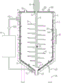
In the first embodiment, a beer fermentation apparatus containing water-soluble cannabidiol, as shown in fig. 1, includes a hollow tank 1 with an open upper end and a cover 2 for sealing the open end of the tank 1, the lower end of the tank 1 is in a reverse taper shape, a rotating shaft 3 is vertically disposed in the tank 1, the rotating shaft 3 is coaxial with the tank 1, a motor 4 is vertically disposed in the center of the cover 2, the upper end of the rotating shaft 3 penetrates through the cover 2 and is connected to an output shaft of the motor 4, the rotating shaft 3 and the cover 2 form a rotating fit through a bearing 5, a helical blade 6 is disposed on the rotating shaft 3 at the circumferential side of one end inside the tank 1, the diameter of the helical blade 6 at the reverse taper position of the tank 1 gradually increases from bottom to top, and the outer diameter of the helical blade 6 is.
In detail, motor 4 drives pivot 3 and rotates, and pivot 3 drives helical blade 6 and uses pivot 3 to rotate as the axle center, and helical blade 6 transports the yeast of depositing in jar body 1 lower extreme to the wort on the upper strata and stir evenly, has certain clearance between helical blade 6 and jar body 1, and less yeast deposit of being convenient for returns jar body 1 bottom.
At least two cooling pipelines 7 are arranged in the tank wall of the tank body 1, in the embodiment, four cooling pipelines 7 are provided, and certainly, two or five cooling pipelines do not influence the protection range of the utility model; at least two cooling pipe 7 set up side by side and are the heliciform and locate jar on 1 body, the lower extreme of two piece at least cooling pipe 7 passes jar body 1 and communicates and have inlet tube 71, the one end that jar body 1 was kept away from to inlet tube 71 is connected with cold water machine 9, the delivery port and the inlet tube 71 intercommunication of cold water machine 9, the water inlet intercommunication of cold water machine 9 has outlet pipe 72, jar body 1 and intercommunication in outlet pipe 72 are passed to the upper end of two piece at least cooling pipe 7, it is equipped with first temperature sensor 31 to inlay on the outer wall of pivot 3, the jar body 1 outside is equipped with controller 8, cold water machine 9 all links with controller 8 electricity with first temperature sensor 31.
In detail, the more the cooling pipelines 7 are, the shorter the cooling pipelines 7 are, the better the cooling effect is, the mutual isolation among the cooling pipelines 7 can ensure that the water pressure difference among the cooling pipelines 7 is not large, and the cooling effect is improved; controller 8 is passed to the wort temperature that first temperature sensor 31 will survey, and when the high temperature, cold water machine 9 work is cooled down jar body 1, and after the temperature dropped to the certain degree, cold water machine 9 stop work.
The heat preservation layer 11 is arranged outside the tank body 1, the cover body 2 is provided with a feeding hole 21 and a pressure gauge 22, the lower end of the tank body 1 is provided with a sewage outlet 12 and a wine outlet 13, and the lower end of the tank body 1 is provided with a support rod 14.
In detail, the heat preservation layer 11 is used for preserving heat of the tank body 1, so that the interference of the external temperature to the temperature in the tank body 1 is prevented; the pressure gauge 22 is used for detecting the pressure condition in the tank body 1; the drain outlet 12 is used for discharging yeast; the wine outlet 13 is used for collecting beer; the support rod 14 is used for supporting the tank body 1 to be far away from the ground, so that the tank body 1 is convenient to place.
Preferably, the lid 2 is provided with a pressure regulating valve 23. Particularly, the air pressure in the tank body 1 is convenient to adjust;
preferably, a plurality of cleaning nozzles 15 are uniformly arranged on the inner wall of the tank 1, the plurality of cleaning nozzles 15 are communicated with a first electromagnetic valve 16, the other end of the first electromagnetic valve 16 is communicated with the cooling pipeline 7, and a second electromagnetic valve 721 is arranged on the water outlet pipe 72. Particularly, the tank body 1 and the helical blade 6 are convenient to clean, the first electromagnetic valve 16 needs to be opened during cleaning, then the second electromagnetic valve 721 needs to be closed, and the cooled water is used for cleaning the interior of the tank body 1, so that the cooling water is convenient to replace.
Preferably, the bottom of the tank body 1 is embedded with a second temperature sensor 17, and the second temperature sensor 17 and the motor 4 are both electrically connected with the controller 8. Specifically, the second temperature sensor 17 transmits the temperature detected at the bottom of the tank 1 to the controller 8, and when the temperature at the bottom of the tank 1 is higher than the temperature at the middle part of the tank 1, the motor 4 works to stir wort.
Example two: as shown in fig. 1, the same features of this embodiment as those of the first embodiment are not described again, and the different features of this embodiment from those of the first embodiment are:
the outer diameter of the helical blade 6 in this embodiment is seventeen-tenths of the inner diameter of the can body 1.
Example three: as shown in fig. 1, the same features of this embodiment as those of the first embodiment are not described again, and the different features of this embodiment from those of the first embodiment are:
the outer diameter of the helical blade 6 in this embodiment is two thirds of the inner diameter of the can body 1.
It should be noted that, the utility model discloses in the ratio between helical blade 6's external diameter and jar body 1 internal diameter not only be limited to embodiment one, embodiment two and embodiment three in show, can also be half to two-thirds between arbitrary ratio, do not influence the utility model discloses a protection scope, the ratio is too big then helical blade 6 will influence the yeast deposit of small part to jar body 1 bottom, also be convenient for homogenize yeast and wheat juice, the ratio is too little then the area that can deposit the yeast on helical blade 6 is less, the effect that reduces the difference in temperature is less.
The present embodiment is only for explaining the present invention, and it is not limited to the present invention, and those skilled in the art can make modifications to the present embodiment without inventive contribution as required after reading the present specification, but all of them are protected by patent laws within the scope of the claims of the present invention.