CN213687637U - Quick environmental protection drying mechanism of plastic grain - Google Patents
Quick environmental protection drying mechanism of plastic grain Download PDFInfo
- Publication number
- CN213687637U CN213687637U CN202022861652.8U CN202022861652U CN213687637U CN 213687637 U CN213687637 U CN 213687637U CN 202022861652 U CN202022861652 U CN 202022861652U CN 213687637 U CN213687637 U CN 213687637U
- Authority
- CN
- China
- Prior art keywords
- conical barrel
- air
- drying mechanism
- air outlet
- mechanism comprises
- Prior art date
- Legal status (The legal status is an assumption and is not a legal conclusion. Google has not performed a legal analysis and makes no representation as to the accuracy of the status listed.)
- Active
Links
Images


Abstract
The utility model belongs to the technical field of a dryer, and discloses a plastic particle rapid environment-friendly drying mechanism, which comprises a conical barrel, wherein the bottom of the conical barrel is provided with a bottom pipe, one side of the conical barrel is provided with a controller, the outer wall of the conical barrel is provided with air blowers adjacent to both sides of the controller, a top cover is arranged above the conical barrel, two air outlet cavities are symmetrically formed inside the conical barrel, the air outlet end of the air blower extends to the inside of the air outlet cavities, one side of the inner wall of the conical barrel, which is close to the air outlet cavities, is provided with an air outlet head, one side of the bottom of the conical barrel, which is close to the inside of the bottom pipe, is provided with a blanking hole, hot air is sprayed out through the air outlet head, and the hot air is sprayed out in an accelerated circulation manner through the structure of the conical barrel, so that the circulation flow rate of the hot air inside the conical barrel is improved, thereby greatly reducing the difficulty of hot air circulation and achieving the effect of improving the efficiency of hot air circulation.
Description
Technical Field
The utility model belongs to the technical field of the desiccator, concretely relates to quick environmental protection drying mechanism of plastic grain.
Background
A dryer is a mechanical device for reducing moisture content of a material by using heat energy, and is used for drying the material, wherein the dryer vaporizes and escapes moisture (generally, moisture or other volatile liquid components) in the material by heating so as to obtain a solid material with a specified moisture content.
But the device on the existing market does not have the structure that improves heated air circulation efficiency, and hot-blast can only be in a single air-out, greatly increased the heated air circulation degree of difficulty, reduced heated air circulation efficiency to the inconvenient dismantlement of the inside stirring structure of device needs to twist a large amount of fixed knot to construct, greatly increased the dismantlement degree of difficulty of stirring structure, reduced the dismantlement efficiency of stirring structure.
SUMMERY OF THE UTILITY MODEL
An object of the utility model is to provide a quick environmental protection drying mechanism of plastic grain to solve the low problem of the dismantlement inefficiency of the hot air circulating inefficiency that provides and stirring structure among the above-mentioned background art.
In order to achieve the above object, the utility model provides a following technical scheme: the utility model provides a quick environmental protection drying mechanism of plastic grain, includes the toper bucket, the bottom tube is installed to the bottom of toper bucket, and one side of toper bucket installs the controller, the air-blower is all installed to the both sides that toper bucket outer wall is adjacent to the controller, the top cap is installed to the top of toper bucket, the inside symmetry of toper bucket is formed with two air-out chambeies, the end of giving vent to anger of air-blower extends to the inside in air-out chamber, the air outlet head is installed to one side that toper bucket inner wall is close to air-out chamber, the blanking hole has been seted up to one side that toper bucket bottom is close to the bottom tube inside, the internally mounted in air-out chamber has the heating pipe, the material pipe is installed to toper bucket.
Preferably, one side fixedly connected with motor that the top cap top is close to the material pipe, the bottom of motor is rotated and is connected with the pivot, the cross rod is installed to the bottom of pivot, spacing seat is installed to cone drum inner wall bottom, the internally mounted of spacing seat has the sill bar, the churn is installed at the top of sill bar, the circumference of churn is personally submitted the annular array and is installed four curb plates, and the cross recess has been seted up at the top of churn.
Preferably, the cross sections of the bottom rod and the limiting seat are both circular, and the diameter of the bottom rod is smaller than that of the limiting seat.
Preferably, the circumference of the bottom tube is in an annular array and is provided with four support rods, and a bottom plate is arranged between the bottoms of the four support rods.
Preferably, four bottom feet are arranged at the bottom of the bottom plate, two of the four bottom feet form a group, and the four bottom feet are symmetrical in pairs.
Preferably, the top of the material pipe is provided with a hopper, and the longitudinal section of the hopper is trapezoidal.
Compared with the prior art, the beneficial effects of the utility model are that:
(1) the utility model discloses a head of giving vent to anger spouts hot-air to through the structure of toper bucket, make hot-air circulation blowout with higher speed, thereby improve the hot-air at the inside circulation velocity of flow of toper bucket, and let the device can many places blowout hot-blastly, thereby greatly reduced the heated air circulation degree of difficulty, reached the effect that improves heated air circulation efficiency.
(2) The utility model discloses a pulling top cap makes the cross rod separate with the cross recess, and the pulling churn makes the churn drive the sill bar and removes, makes sill bar and spacing separation of seat, can take out the churn from the conical drum, lets the inside stirring structure convenient to detach of device, need not to twist and moves a large amount of fixed knot and construct, greatly reduced the dismantlement degree of difficulty of stirring structure, improved the dismantlement efficiency of stirring structure.
Drawings
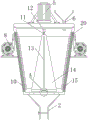
Fig. 1 is a schematic structural view of the present invention;
FIG. 2 is a view showing the inner structure of the cone-shaped barrel of the present invention;
FIG. 3 is a bottom view of the cone-shaped barrel of the present invention;
FIG. 4 is an enlarged view of portion A of FIG. 2;
FIG. 5 is a top view of the cross bar of the present invention when connected to the mixing drum;
fig. 6 is a bottom view of the rotating shaft of the present invention;
FIG. 7 is an internal structure view of the utility model when the bottom rod is connected with the limiting seat;
in the figure: 1. a support bar; 2. a bottom tube; 3. a controller; 4. a top cover; 5. a motor; 6. a material pipe; 7. a conical barrel; 8. a blower; 9. a base plate; 10. an air outlet cavity; 11. a cross bar; 12. a rotating shaft; 13. a side plate; 14. a mixing drum; 15. an air outlet head; 16. a blanking hole; 17. a bottom bar; 18. a limiting seat; 19. a cross groove; 20. heating a tube; 21. footing; 22. and (4) a hopper.
Detailed Description
The technical solutions in the embodiments of the present invention will be described clearly and completely with reference to the accompanying drawings in the embodiments of the present invention, and it is obvious that the described embodiments are only some embodiments of the present invention, not all embodiments. Based on the embodiments in the present invention, all other embodiments obtained by a person skilled in the art without creative work belong to the protection scope of the present invention.
Referring to fig. 1-7, the present invention provides the following technical solutions: the utility model provides a quick environmental protection drying mechanism of plastic grain, including toper bucket 7, bottom tube 2 is installed to the bottom of toper bucket 7, and controller 3 is installed to one side of toper bucket 7, air-blower 8 is all installed adjacent to controller 3's both sides to toper bucket 7 outer wall, top cap 4 is installed to toper bucket 7's top, toper bucket 7's inside symmetry is formed with two air-out chambeies 10, air-blower 8's the end of giving vent to anger extends to the inside in air-out chamber 10, air outlet head 15 is installed to one side that toper bucket 7 inner wall is close to air-out chamber 10, blanking hole 16 has been seted up to one side that toper bucket 7 bottom is close to bottom tube 2 inside, air-out chamber 10's internally mounted has heating pipe 20, material pipe 6 is installed at toper bucket 7 top, through air outlet head 15 blowout hot-air, and through toper bucket 7, make spun hot-air circulation accelerate, improve hot air flow rate.
Further, a motor 5 is fixedly connected to one side of the top cover 4 close to the material pipe 6, a rotating shaft 12 is rotatably connected to the bottom of the motor 5, a cross rod 11 is installed at the bottom of the rotating shaft 12, a limiting seat 18 is installed at the bottom end of the inner wall of the conical barrel 7, a bottom rod 17 is installed inside the limiting seat 18, a stirring barrel 14 is installed at the top of the bottom rod 17, four side plates 13 are installed on the circumference of the stirring barrel 14 in an annular array, a cross groove 19 is formed in the top of the stirring barrel 14, the blower 8, the heating pipe 20 and the motor 5 are all electrically connected with the controller 3, the motor 5 adopts a Y2-90L-4 driving motor, the controller 3 adopts a PLC (programmable logic controller) editable controller, the model is a PLC CPU226, the cross rod 11 is inserted into the cross groove 19, the bottom rod 17 is clamped with the limiting seat 18, when the stirring barrel 14 needs to be disassembled, the bottom rod 17 and the limiting seat 18 can be separated by pulling the mixing drum 14, so that the mixing drum 14 is convenient to disassemble.
Furthermore, the cross sections of the bottom rod 17 and the limiting seat 18 are both circular, the diameter of the bottom rod 17 is smaller than that of the limiting seat 18, and the bottom rod 17 can be inserted conveniently through the limiting seat 18 with a larger diameter.
Further, the circumference of bottom tube 2 is personally submitted the annular array and is installed four bracing pieces 1, installs bottom plate 9 between four bracing pieces 1 bottoms, supports bottom tube 2 through four bracing pieces 1, lets bottom tube 2 stabilize and places.
Further, four footing 21 are installed to bottom plate 9 bottom, and four footing 21 are two and are a set of, and two bisymmetry supports bottom plate 9 through four footing 21, lets bottom plate 9 place firmly.
Furthermore, a hopper 22 is installed on the top of the material pipe 6, the longitudinal section of the hopper 22 is trapezoidal, and raw materials can be conveniently added into the material pipe 6 through the hopper 22.
The utility model discloses a theory of operation and use flow: when the utility model is used, the conical barrel 7 is supported by the support rod 1 and the bottom plate 9, the conical barrel 7 is placed stably, plastic particles to be dried are added into the conical barrel 7 through the material pipe 6, the air blower 8 works to lead the external air into the air outlet cavity 10, the air is heated through the heating pipe 20, hot air is sprayed out through the air outlet head 15, the rotating shaft 12 is driven to rotate through the motor 5, the cross rod 11 is driven to rotate, the cross rod 11 drives the stirring cylinder 14 to rotate, the side plate 13 is driven to rotate, the plastic particles are stirred through the side plate 13, the sprayed hot air is accelerated to rotate through the structure of the conical barrel 7, the drying efficiency of the plastic particles is accelerated, the plastic particles are led into the bottom pipe 2 through the blanking hole 16, the valve on one side of the bottom pipe 2 is unscrewed, the plastic particles can be discharged, when the stirring cylinder 14 needs to be dismounted, the top cover 4 is pulled upwards, the cross rod 11 is separated from the cross groove 19, the mixing drum 14 is pulled upwards, the bottom rod 17 is separated from the limiting seat 18, and the mixing drum 14 can be taken out.
It is noted that, herein, relational terms such as first and second, and the like may be used solely to distinguish one entity or action from another entity or action without necessarily requiring or implying any actual such relationship or order between such entities or actions. Also, the terms "comprises," "comprising," or any other variation thereof, are intended to cover a non-exclusive inclusion, such that a process, method, article, or apparatus that comprises a list of elements does not include only those elements but may include other elements not expressly listed or inherent to such process, method, article, or apparatus.
Although embodiments of the present invention have been shown and described, it will be appreciated by those skilled in the art that changes, modifications, substitutions and alterations can be made in these embodiments without departing from the principles and spirit of the invention, the scope of which is defined in the appended claims and their equivalents.
Claims (6)
1. The utility model provides a quick environmental protection drying mechanism of plastic grain which characterized in that: including conical barrel (7), bottom tube (2) are installed to the bottom of conical barrel (7), and one side of conical barrel (7) installs controller (3), air-blower (8) are all installed adjacent to the both sides of controller (3) to conical barrel (7) outer wall, top cap (4) are installed to the top of conical barrel (7), the inside symmetry of conical barrel (7) is formed with two air-out chambeies (10), the end of giving vent to anger of air-blower (8) extends to the inside in air-out chamber (10), air outlet head (15) are installed to one side that conical barrel (7) inner wall is close to air-out chamber (10), blanking hole (16) have been seted up near bottom tube (2) inside one side in conical barrel (7) bottom, the internally mounted in air-out chamber (10) has heating pipe (20), material pipe (6) are installed at conical barrel (7) top.
2. The apparatus of claim 1, wherein the drying mechanism comprises: top cap (4) top is close to one side fixedly connected with motor (5) of material pipe (6), the bottom of motor (5) is rotated and is connected with pivot (12), cross rod (11) are installed to the bottom of pivot (12), spacing seat (18) are installed to cone drum (7) inner wall bottom, the internally mounted of spacing seat (18) has sill bar (17), churn (14) are installed at the top of sill bar (17), the circumference of churn (14) is personally submitted the annular array and is installed four curb plates (13), and cross recess (19) have been seted up at the top of churn (14).
3. The apparatus of claim 2, wherein the drying mechanism comprises: the cross sections of the bottom rod (17) and the limiting seat (18) are circular, and the diameter of the bottom rod (17) is smaller than that of the limiting seat (18).
4. The apparatus of claim 1, wherein the drying mechanism comprises: the circumference of bottom tube (2) is personally submitted annular array and is installed four bracing pieces (1), installs bottom plate (9) between four bracing piece (1) bottoms.
5. The apparatus of claim 4, wherein the drying mechanism comprises: four bottom feet (21) are installed at the bottom of the bottom plate (9), two of the four bottom feet (21) form a group, and the four bottom feet are symmetrical in pairs.
6. The apparatus of claim 1, wherein the drying mechanism comprises: the top of the material pipe (6) is provided with a hopper (22), and the longitudinal section of the hopper (22) is trapezoidal.
Priority Applications (1)
| Application Number | Priority Date | Filing Date | Title |
|---|---|---|---|
| CN202022861652.8U CN213687637U (en) | 2020-12-02 | 2020-12-02 | Quick environmental protection drying mechanism of plastic grain |
Applications Claiming Priority (1)
| Application Number | Priority Date | Filing Date | Title |
|---|---|---|---|
| CN202022861652.8U CN213687637U (en) | 2020-12-02 | 2020-12-02 | Quick environmental protection drying mechanism of plastic grain |
Publications (1)
| Publication Number | Publication Date |
|---|---|
| CN213687637U true CN213687637U (en) | 2021-07-13 |
Family
ID=76737750
Family Applications (1)
| Application Number | Title | Priority Date | Filing Date |
|---|---|---|---|
| CN202022861652.8U Active CN213687637U (en) | 2020-12-02 | 2020-12-02 | Quick environmental protection drying mechanism of plastic grain |
Country Status (1)
| Country | Link |
|---|---|
| CN (1) | CN213687637U (en) |
-
2020
- 2020-12-02 CN CN202022861652.8U patent/CN213687637U/en active Active
Similar Documents
| Publication | Publication Date | Title |
|---|---|---|
| CN203964589U (en) | Granule materials drying machine | |
| CN201417061Y (en) | Highly-efficient multi-purpose single-cone drier | |
| CN104596216B (en) | The drying machine of plastic bottle sheet | |
| CN106091594A (en) | A kind of Production of Medicinal Liqueur medicinal residues drying device | |
| CN213687637U (en) | Quick environmental protection drying mechanism of plastic grain | |
| CN208002022U (en) | A kind of tea drier of automatic turning tealeaves | |
| CN208810195U (en) | Crushing material mixing all-in-one machine | |
| CN204322569U (en) | Industrial chemicals extrusion forming device | |
| CN209689322U (en) | A kind of drying device for Erding granules | |
| CN204656615U (en) | Construction material extruding treatment appts | |
| CN206810210U (en) | A kind of vertical drying storing blender | |
| CN104534834A (en) | Energy-saving dryer | |
| CN210267986U (en) | High-efficient drying device for biological fermentation engineering | |
| CN204346065U (en) | Inner-outer circulation drying unit | |
| CN208817903U (en) | A kind of capsule drying rotating cage | |
| CN209197350U (en) | It is a kind of for producing the heated-air circulation oven of condensed pill | |
| CN210862061U (en) | Car plastic particle drying device | |
| CN209095779U (en) | A kind of plastics-production stirring drier | |
| CN207415750U (en) | A kind of particle dries mixer | |
| CN209214173U (en) | A kind of lift cooling device for rice | |
| CN207649234U (en) | A kind of plastic grain drying unit | |
| CN105972957A (en) | Plastic particle drying device | |
| CN205784366U (en) | Plastic pellet drying unit | |
| CN204525839U (en) | A kind of efficient materal drier | |
| CN210441579U (en) | Dehydration drying device for preparing high-molecular water-absorbent resin |
Legal Events
| Date | Code | Title | Description |
|---|---|---|---|
| GR01 | Patent grant | ||
| GR01 | Patent grant |