CN213683159U - Guide unloading device of attached scaffold - Google Patents
Guide unloading device of attached scaffold Download PDFInfo
- Publication number
- CN213683159U CN213683159U CN202021931349.4U CN202021931349U CN213683159U CN 213683159 U CN213683159 U CN 213683159U CN 202021931349 U CN202021931349 U CN 202021931349U CN 213683159 U CN213683159 U CN 213683159U
- Authority
- CN
- China
- Prior art keywords
- box body
- outer box
- plates
- plate
- supporting
- Prior art date
- Legal status (The legal status is an assumption and is not a legal conclusion. Google has not performed a legal analysis and makes no representation as to the accuracy of the status listed.)
- Expired - Fee Related
Links
- 238000013016 damping Methods 0.000 claims description 10
- 230000008878 coupling Effects 0.000 abstract 1
- 238000010168 coupling process Methods 0.000 abstract 1
- 238000005859 coupling reaction Methods 0.000 abstract 1
- 238000000034 method Methods 0.000 description 12
- 239000002699 waste material Substances 0.000 description 3
- 238000010276 construction Methods 0.000 description 2
- 238000005516 engineering process Methods 0.000 description 2
- OKTJSMMVPCPJKN-UHFFFAOYSA-N Carbon Chemical compound [C] OKTJSMMVPCPJKN-UHFFFAOYSA-N 0.000 description 1
- 230000004075 alteration Effects 0.000 description 1
- 230000009286 beneficial effect Effects 0.000 description 1
- 230000002457 bidirectional effect Effects 0.000 description 1
- 230000003139 buffering effect Effects 0.000 description 1
- 229910052799 carbon Inorganic materials 0.000 description 1
- 230000000694 effects Effects 0.000 description 1
- 238000012986 modification Methods 0.000 description 1
- 230000004048 modification Effects 0.000 description 1
- 238000006467 substitution reaction Methods 0.000 description 1
Images


Landscapes
- Conveying And Assembling Of Building Elements In Situ (AREA)
Abstract
The utility model discloses an inserted scaffold's direction off-load device, including supporting baseplate and outer box, the support curb plate is all installed to the up end left and right sides of supporting baseplate, and supports the curb plate and be close to the position of the vertical central line of supporting baseplate and install fixed diaphragm, the swash plate is installed to the below of fixed diaphragm, the upper end of supporting baseplate is installed and is driven actuating cylinder, and drives actuating cylinder's upper end and be connected with the telescopic link, outer box body coupling is in the upper end of telescopic link, the left and right sides of outer box all is fixed with the T-shaped board, and the T-shaped board keeps away from the position of the vertical central line of outer box and installs the deflector. This attached scaffold's direction unloading device is provided with mutually perpendicular between supporting baseplate and the support curb plate, has guaranteed that the support curb plate is in vertical state, and mutually perpendicular has guaranteed that the fixed diaphragm is in the horizontally state between support curb plate and the fixed diaphragm, so can guarantee that whole device is in the two-way balance of vertical and horizontal direction.
Description
Technical Field
The utility model relates to an unloading device technical field specifically is a direction unloading device of inserted scaffold frame.
Background
The attached lifting scaffold equipment is a novel scaffold technology which is rapidly developed in the early century, and has important influence on the progress of construction technology in China. It becomes the low place operation with the altitude construction, becomes the inside operation of support body with unsettled operation, has apparent low carbon nature, high-tech content and characteristics such as more economical, safer, more convenient, and the off-load is exactly just to remove the power that the object bore briefly.
The existing attached type lifting scaffold unloading device has potential safety hazards due to the fact that the ground is uneven and the like in the working process, the existing attached type lifting scaffold unloading device cannot well keep balance, and due to the fact that a guide device is lacked in the moving process, time and labor are wasted in the moving process, the use requirements of people cannot be well met, and technical innovation is conducted on the basis of the existing attached type scaffold guiding unloading device aiming at the situations.
SUMMERY OF THE UTILITY MODEL
An object of the utility model is to provide a direction off-load device of inserted scaffold to it because reasons such as ground unevenness can't fine keep balance nature to provide current inserted lift scaffold off-load device in the working process to solve among the above-mentioned background art, has the potential safety hazard, and removes the in-process and lack guider, leads to the removal process to waste time and energy, can not be fine satisfies people's user demand problem.
In order to achieve the above object, the utility model provides a following technical scheme: a guide unloading device of an attached scaffold comprises a support bottom plate and an outer box body, wherein support side plates are respectively arranged on the left side and the right side of the upper end surface of the support bottom plate, a fixed transverse plate is arranged at the position of the supporting side plate close to the vertical central line of the supporting bottom plate, an inclined plate is arranged below the fixed transverse plate, a driving cylinder is arranged at the upper end of the supporting bottom plate, the upper end of the driving cylinder is connected with a telescopic rod, the outer box body is connected with the upper end of the telescopic rod, T-shaped plates are fixed on the left side and the right side of the outer box body, and the T-shaped plate is provided with a guide plate at the position far away from the vertical central line of the outer box body, a limit chute is arranged inside the guide plate, a positioning back plate is arranged at the back side of the outer box body, a return spring is arranged in the outer box body, and a damping column is arranged at the position of the return spring close to the vertical central line of the outer box body, and the upper end of the return spring is connected with the inner box body.
Preferably, the supporting bottom plate and the supporting side plates are perpendicular to each other, and the supporting side plates are symmetrically distributed about the vertical center line of the supporting bottom plate.
Preferably, the supporting side plates are perpendicular to the fixing transverse plates, and the number of the fixing transverse plates is three.
Preferably, a semi-surrounding structure is formed between the outer box body and the inner box body, and the outer box body and the positioning rear plate are parallel to each other.
Preferably, the driving cylinder forms a telescopic structure through the telescopic rod and the outer box body, and the outer box body forms a sliding structure through the T-shaped plate, the limiting sliding groove and the guide plate.
Preferably, the inner box body and the outer box body form an elastic structure through a return spring, and the damping columns are symmetrically distributed about the vertical center line of the inner box body.
Preferably, the inclined angle between the inclined plate and the fixed transverse plate is 45 degrees, and the inclined plates are four.
Compared with the prior art, the beneficial effects of the utility model are as follows:
1. the utility model discloses be provided with between supporting baseplate and the support curb plate mutually perpendicular, guaranteed that the support curb plate is in vertical state, mutually perpendicular between support curb plate and the fixed diaphragm, guaranteed that the fixed diaphragm is in horizontal state, so can guarantee that whole device is in the two-way balance of vertical and horizontal direction, solved current attached lift scaffold unloading device in the course of the work because reasons such as ground unevenness can't be fine keep balance, have the problem of potential safety hazard;
2. the utility model is provided with the outer box body to facilitate the bearing of the inner box body, the positioning back plate is convenient for connecting the guide plate, the driving cylinder can drive the outer box body to move up and down through the telescopic rod, the moving track of the outer box body can be determined through the limiting sliding groove, and the guide plate plays a role in guiding the movement of the outer box body, thereby avoiding the problem that the moving process wastes time and labor due to the lack of a guide device in the moving process;
3. the utility model discloses be provided with return spring and can guarantee the balance of box left and right sides power, the damping post plays the supporting role to the internal box, and the swash plate plays the fixed action to playing support curb plate and fixed diaphragm, guarantees its stability, greatly increased this kind of attached scaffold's direction off-load device's practicality.
Drawings
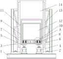
FIG. 1 is a schematic view of the structure of the present invention;
fig. 2 is a schematic top view of the positioning back plate of the present invention;
FIG. 3 is a schematic view of the connecting structure of the supporting side plates and the fixed transverse plate of the present invention;
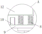
fig. 4 is a schematic view of a part of an enlarged structure at a in fig. 1 according to the present invention.
In the figure: 1. a support base plate; 2. supporting the side plates; 3. fixing the transverse plate; 4. a driving cylinder; 5. a telescopic rod; 6. a sloping plate; 7. a limiting chute; 8. a return spring; 9. an outer case; 10. a damping column; 11. a T-shaped plate; 12. an inner box body; 13. a guide plate; 14. the back plate is positioned.
Detailed Description
The technical solutions in the embodiments of the present invention will be described clearly and completely with reference to the accompanying drawings in the embodiments of the present invention, and it is obvious that the described embodiments are only some embodiments of the present invention, not all embodiments. Based on the embodiments in the present invention, all other embodiments obtained by a person skilled in the art without creative work belong to the protection scope of the present invention.
Referring to fig. 1-4, the present invention provides a technical solution: a guiding unloading device of an attached scaffold comprises a supporting bottom plate 1 and an outer box body 9, wherein supporting side plates 2 are respectively installed on the left side and the right side of the upper end surface of the supporting bottom plate 1, fixing transverse plates 3 are installed at positions, close to the vertical central line of the supporting bottom plate 1, of the supporting side plates 2, inclined plates 6 are installed below the fixing transverse plates 3, a driving cylinder 4 is installed at the upper end of the supporting bottom plate 1, a telescopic rod 5 is connected to the upper end of the driving cylinder 4, the outer box body 9 is connected to the upper end of the telescopic rod 5, T-shaped plates 11 are respectively fixed on the left side and the right side of the outer box body 9, a guide plate 13 is installed at a position, far away from the vertical central line of the outer box body 9, of each T-shaped plate 11, a limiting chute 7 is arranged inside each guide plate 13, a positioning rear plate 14 is installed at the rear side of the, the upper end of the return spring 8 is connected with an inner box body 12.
The utility model discloses in: the supporting bottom plate 1 and the supporting side plates 2 are perpendicular to each other, and the supporting side plates 2 are symmetrically distributed around the vertical center line of the supporting bottom plate 1; the supporting bottom plate 1 and the supporting side plate 2 are perpendicular to each other, so that the supporting side plate 2 is ensured to be in a vertical state.
The utility model discloses in: the supporting side plates 2 are vertical to the fixed transverse plates 3, and three fixed transverse plates 3 are arranged in each group; supporting between curb plate 2 and the fixed diaphragm 3 mutually perpendicular, having guaranteed that fixed diaphragm 3 is in the horizontally state, so can guarantee that whole device is in the two-way balance of vertical and horizontal direction, solved current inserted lift scaffold unloading device in the course of the work because reasons such as ground unevenness can't be fine keep balance, have the problem of potential safety hazard.
The utility model discloses in: a semi-surrounding structure is formed between the outer box body 9 and the inner box body 12, and the outer box body 9 and the positioning rear plate 14 are parallel to each other; the outer housing 9 facilitates the carrying of the inner housing 12 and the positioning of the back plate 14 facilitates the attachment of the guide plate 13.
The utility model discloses in: the driving cylinder 4 and the outer box body 9 form a telescopic structure through the telescopic rod 5, and the outer box body 9 and the guide plate 13 form a sliding structure through the T-shaped plate 11 and the limiting sliding chute 7; drive actuating cylinder 4 and can drive outer box 9 through telescopic link 5 and reciprocate, can confirm the removal orbit of outer box 9 through spacing spout 7, deflector 13 plays the guide effect to its removal, has avoided removing the in-process and has lacked guider, leads to the removal process problem that wastes time and energy.
The utility model discloses in: the inner box body 12 and the outer box body 9 form an elastic structure through a return spring 8, and the damping columns 10 are symmetrically distributed about the vertical center line of the inner box body 12; the return spring 8 can ensure the balance of forces on the left side and the right side of the inner box body 12, and the damping columns 10 play a role in supporting the inner box body 12.
The utility model discloses in: the included angle between the inclined plate 6 and the fixed transverse plate 3 is 45 degrees, and four inclined plates 6 are arranged; the inclined plate 6 plays a role in fixing the supporting side plate 2 and the fixing transverse plate 3, the stability of the inclined plate is guaranteed, and the practicability of the guide unloading device of the attached scaffold is greatly improved.
The guide unloading device of the attached scaffold has the working principle that: firstly, the supporting bottom plate 1 plays a role in bearing the device, the supporting bottom plate 1 and the positioning rear plate 14 are fixed on a building through a threaded rod, and the supporting bottom plate 1 is ensured to be in a horizontal state by means of a level gauge in the fixing process; secondly, the supporting side plates 2 are arranged on two sides of the supporting bottom plate 1 and are also in a vertical state, the fixing transverse plate 3 is in a horizontal state, the inclined plate 6 plays a role in fixing the supporting side plates 2 and the fixing transverse plate 3, the stability of the device is ensured, the whole device can be ensured to be in bidirectional balance in the vertical and horizontal directions, and potential safety hazards caused by the lack of balance of the device due to uneven ground and the like are avoided; then when the scaffold needs to be moved, the driving cylinder 4 is started, the driving cylinder 4 drives the outer box body 9 to move upwards or downwards through the telescopic rod 5, the inner box body 12 in the outer box body 9 moves simultaneously, the moving track of the outer box body 9 is determined by moving in the limiting sliding groove 7 of the T-shaped plate 11, the guide plate 13 plays a role in guiding the movement of the outer box body, the moving process is time-saving and labor-saving, and the positioning rear plate 14 is convenient for connecting the guide plate 13; finally, when one side of the inner box body 12 inclines, the inner box body 12 can be stretched towards the opposite direction through the return spring 8 at the opposite side, the balance of forces at the left side and the right side is kept, and the damping columns 10 play a role in supporting the inner box body 12 and play a role in damping and buffering.
Although embodiments of the present invention have been shown and described, it will be appreciated by those skilled in the art that changes, modifications, substitutions and alterations can be made in these embodiments without departing from the principles and spirit of the invention, the scope of which is defined in the appended claims and their equivalents.
Claims (7)
1. The utility model provides an attached scaffold's direction off-load device, includes supporting baseplate (1) and outer box (9), its characterized in that: the supporting side plates (2) are installed on the left side and the right side of the upper end face of the supporting base plate (1), the supporting side plates (2) are installed at positions, close to the vertical central line of the supporting base plate (1), of the supporting side plates (2) to form fixed transverse plates (3), inclined plates (6) are installed below the fixed transverse plates (3), driving cylinders (4) are installed at the upper end of the supporting base plate (1), telescopic rods (5) are connected to the upper ends of the driving cylinders (4), the outer box body (9) is connected to the upper ends of the telescopic rods (5), T-shaped plates (11) are fixed to the left side and the right side of the outer box body (9), guide plates (13) are installed at positions, far away from the vertical central line of the outer box body (9), limiting sliding grooves (7) are arranged inside the guide plates (13), positioning rear plates (14) are installed on the rear side of the outer box body (9), and, and a damping column (10) is installed at a position, close to the vertical central line of the outer box body (9), of the return spring (8), and the upper end of the return spring (8) is connected with the inner box body (12).
2. A guided unloading device of an attached scaffold according to claim 1, wherein: the supporting bottom plate (1) and the supporting side plates (2) are perpendicular to each other, and the supporting side plates (2) are symmetrically distributed around the vertical center line of the supporting bottom plate (1).
3. A guided unloading device of an attached scaffold according to claim 1, wherein: the supporting side plates (2) and the fixed transverse plates (3) are perpendicular to each other, and the number of the fixed transverse plates (3) in each group is three.
4. A guided unloading device of an attached scaffold according to claim 1, wherein: a semi-surrounding structure is formed between the outer box body (9) and the inner box body (12), and the outer box body (9) and the positioning rear plate (14) are parallel to each other.
5. A guided unloading device of an attached scaffold according to claim 1, wherein: the driving cylinder (4) forms a telescopic structure with the outer box body (9) through a telescopic rod (5), and the outer box body (9) forms a sliding structure with the guide plate (13) through a T-shaped plate (11) and a limiting sliding groove (7).
6. A guided unloading device of an attached scaffold according to claim 1, wherein: the inner box body (12) and the outer box body (9) form an elastic structure through a return spring (8), and the damping columns (10) are symmetrically distributed about the vertical center line of the inner box body (12).
7. A guided unloading device of an attached scaffold according to claim 1, wherein: the included angle between the inclined plate (6) and the fixed transverse plate (3) is 45 degrees, and the inclined plates (6) are provided with four.
Priority Applications (1)
| Application Number | Priority Date | Filing Date | Title |
|---|---|---|---|
| CN202021931349.4U CN213683159U (en) | 2020-09-07 | 2020-09-07 | Guide unloading device of attached scaffold |
Applications Claiming Priority (1)
| Application Number | Priority Date | Filing Date | Title |
|---|---|---|---|
| CN202021931349.4U CN213683159U (en) | 2020-09-07 | 2020-09-07 | Guide unloading device of attached scaffold |
Publications (1)
| Publication Number | Publication Date |
|---|---|
| CN213683159U true CN213683159U (en) | 2021-07-13 |
Family
ID=76746863
Family Applications (1)
| Application Number | Title | Priority Date | Filing Date |
|---|---|---|---|
| CN202021931349.4U Expired - Fee Related CN213683159U (en) | 2020-09-07 | 2020-09-07 | Guide unloading device of attached scaffold |
Country Status (1)
| Country | Link |
|---|---|
| CN (1) | CN213683159U (en) |
-
2020
- 2020-09-07 CN CN202021931349.4U patent/CN213683159U/en not_active Expired - Fee Related
Similar Documents
| Publication | Publication Date | Title |
|---|---|---|
| CN212670344U (en) | Bridge maintenance jacking device for municipal bridge engineering | |
| CN217233383U (en) | Hydraulic engineering overhauls cat ladder | |
| CN209942387U (en) | Rail guard for construction | |
| CN215484421U (en) | Mortar collection device for wall plastering | |
| CN109723238B (en) | Civil engineering building pillar | |
| CN212695514U (en) | A lifting device for installation of power distribution cabinet | |
| CN212200001U (en) | Ground tamping device for road administration construction | |
| CN204566377U (en) | A kind of precast beam steel strand pulling machine hoisting frame device | |
| CN218565164U (en) | A movable beacon for building site construction night | |
| CN220334715U (en) | Ground grabbing structure of scissor type lifting platform | |
| CN210737372U (en) | Highway bridge hydraulic pressure heel post | |
| CN220745263U (en) | Vertical elevator | |
| CN214659011U (en) | Building engineering construction protector | |
| CN210431070U (en) | Motor box sheet metal part | |
| CN224032201U (en) | Beam reinforcement cushion block positioning tool | |
| CN214577121U (en) | A new type of underground excavation construction support frame | |
| CN221955780U (en) | A kind of electric power maintenance equipment capable of lifting and lowering | |
| CN222730369U (en) | A temporary support device for installing a steel structure bridge | |
| CN215558345U (en) | Liftable support for construction engineering construction | |
| CN220539208U (en) | Building engineering template | |
| CN220167441U (en) | Building climbing frame | |
| CN216657473U (en) | Ceiling polishing device for flat slab | |
| CN217182708U (en) | Switch board base convenient to remove | |
| CN221917019U (en) | Stable placement platform for crane | |
| CN214570028U (en) | Be used for mud flat photovoltaic construction battery piece upper rack hoist device |
Legal Events
| Date | Code | Title | Description |
|---|---|---|---|
| GR01 | Patent grant | ||
| GR01 | Patent grant | ||
| CF01 | Termination of patent right due to non-payment of annual fee |
Granted publication date: 20210713 |
|
| CF01 | Termination of patent right due to non-payment of annual fee |