Hepatobiliary pancreas surgery pipe fixing device
Technical Field
The utility model relates to the technical field of medical equipment, specifically a hepatobiliary pancreas surgery pipe fixing device.
Background
Along with the development of the times, in order to reduce the pain of people caused by diseases, medical instruments are more and more comprehensive, during clinical interventional therapy, the catheters are usually inserted into the abdomen and need to be positioned generally, the catheters are usually fixed by gauze and adhesive tapes, in actual use, the catheters are easy to fall off or shake, the use safety is not high, and when the external catheters shake, the internal catheters can be involved to shift, the comfort is not good, and unnecessary pain is caused to patients.
Therefore, a hepatobiliary-pancreatic surgical catheter fixing device is designed.
SUMMERY OF THE UTILITY MODEL
The utility model provides a not enough to prior art, the utility model provides a hepatobiliary pancreas surgery pipe fixing device has solved current hepatobiliary pancreas surgery pipe fixing device when using, and the pipe drops easily or rocks, and the security of getting up is not high, and can lead to inside pipe aversion when the pipe activity of outside rocks, and the travelling comfort is not good, leads to unnecessary painful problem for the patient.
In order to achieve the above purpose, the utility model adopts the technical scheme that:
the utility model provides a hepatobiliary pancreas surgery pipe fixing device, which comprises a fixing plate and i, the preceding terminal surface of fixed plate has been seted up and has been led to the chamber, the preceding terminal surface of fixed plate still fixedly connected with half ring cover one, the front end of fixed plate still fixedly connected with fixed block, a side of fixed block is seted up flutedly, be provided with the regulation pole in the recess, the side fixedly connected with and the recess assorted slider of regulation pole, be provided with the spring between the embedded face of slider and recess, the spring housing is located on the regulation pole, the one end of regulation pole extends to outside the recess and fixedly connected with half ring cover two, the one end of half ring cover two and the preceding terminal surface sliding connection of fixed plate, the medial surface fixedly connected with assorted elasticity fixture block of half ring cover one and half ring cover two, the other end of regulation pole runs through the embedded face of recess and extends to outside the fixed block.
Furthermore, the rear end face of the first binding band is fixedly connected with a hook-and-loop fastener hook face, and the front end face of the second binding band is fixedly connected with a hook-and-loop fastener hair face.
Furthermore, the front end face of the fixed plate is provided with a bent pipe, the outer side face of the bent pipe is fixedly connected with a fixed sleeve, and the side face of the fixed sleeve is fixedly connected with the front end face of the fixed plate through symmetrically arranged connecting rods.
Furthermore, the rear end face of the fixing plate is fixedly connected with a matched protective pad.
Furthermore, the adjusting rod penetrates through the embedded surface in the groove and extends to one end outside the fixing block to be fixedly connected with a pull ring.
Furthermore, the inner side surface of the pull ring is fixedly connected with a matched rubber gasket.
The utility model has the advantages that:
1. when the utility model is used, the whole device is fixed on the waist of a patient through the first binding belt and the second binding belt, the adjusting rod is pulled rightwards firstly, the horizontal right movement of the adjusting rod drives the sliding block to horizontally move rightwards in the groove, the spring is extruded, the right movement of the adjusting rod simultaneously drives the right movement of the half-ring sleeve to expose the through cavity arranged on the front end surface of the fixed plate, the conduit penetrates through the through cavity to be inserted into the pipe, after the pipe is inserted into the pipe, the adjusting rod is loosened, the elasticity of the spring pushes the horizontal left movement of the sliding block, the horizontal movement of the sliding block drives the horizontal left movement of the adjusting rod, the horizontal left movement of the adjusting rod drives the horizontal movement of the half-ring sleeve to fix the conduit by the elastic clamping blocks on the inner side surfaces of the half-ring sleeve and the half-ring sleeve, the phenomenon of separation in the use process of the conduit is avoided, the safety performance is high, moreover, the conduit is clamped and fixed by the conduit through the, thereby avoiding unnecessary pain of the patient caused by the movement of the external catheter, having good comfort, being convenient for the patient to use, and being simple and convenient for the medical care personnel to operate.
2. The utility model discloses a hook face and magic tape hair side are pasted to magic through setting up, are convenient for be fixed in the patient health with the device through bandage one and bandage two on, and use convenient and fast, through the return bend that sets up, when using, run through the return bend with the pipe, the pipe passes through the return bend bending, can avoid the pipe to take place to bend and influence the circulation of pipe.
Drawings
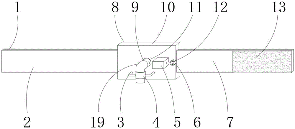
Fig. 1 is a schematic structural view of the present invention;
FIG. 2 is a schematic view of the present invention in partial section;
fig. 3 is a schematic structural diagram of the section of the middle fixing block of the present invention.
In the figure: 1. hook surface of magic tape; 2. binding a first belt; 3. a connecting rod; 4. fixing a sleeve; 5. a fixed block; 6. a pull ring; 7. a second binding band; 8. a protective pad; 9. the half ring is sleeved with a first ring; 10. a fixing plate; 11. a second half ring sleeve; 12. adjusting a rod; 13. magic tape hair side; 14. an elastic clamping block; 15. a cavity is communicated; 16. a slider; 17. a groove; 18. a spring; 19. and (5) bending the pipe.
Detailed Description
In order to make the objects, technical solutions and advantages of the embodiments of the present invention clearer, the embodiments of the present invention will be clearly and completely described below with reference to the accompanying drawings in the embodiments of the present invention, and it is obvious that the described embodiments are some, but not all, embodiments of the present invention. Based on the embodiments in the present invention, all other embodiments obtained by a person skilled in the art without creative efforts belong to the protection scope of the present invention.
Referring to FIGS. 1-3: a hepatobiliary pancreas surgery catheter fixing device comprises a fixing plate 10, wherein a through cavity 15 is formed in the front end face of the fixing plate 10, a first half ring sleeve 9 is fixedly connected to the front end face of the fixing plate 10, a fixing block 5 is fixedly connected to the front end of the fixing plate 10, a groove 17 is formed in one side face of the fixing block 5, an adjusting rod 12 is arranged in the groove 17, a sliding block 16 matched with the groove 17 is fixedly connected to the side face of the adjusting rod 12, a spring 18 is arranged between the sliding block 16 and the embedded face of the groove 17, the spring 18 is sleeved on the adjusting rod 12, one end of the adjusting rod 12 extends out of the groove 17 and is fixedly connected with a second half ring sleeve 11, one end of the second half ring sleeve 11 is slidably connected with the front end face of the fixing plate 10, matched elastic clamping blocks 14 are fixedly connected to the inner side faces of the first half ring sleeve 9 and the second half ring, one side surface of the fixing plate 10 is fixedly connected with a first binding band 2, and the other side surface of the fixing plate 10 is fixedly connected with a second binding band 7.
Bandage 2's rear end face fixedly connected with magic subsides hook face 1, bandage two 7 preceding terminal surface fixedly connected with magic subsides matte 13, through the magic subsides hook face 1 and the magic subsides matte 13 that set up, be convenient for through bandage one 2 and bandage two 7 with the device be fixed in on the patient's health, and use convenient and fast.
The preceding terminal surface of fixed plate 10 is provided with return bend 19, and the fixed cover 4 of lateral surface fixedly connected with of return bend 19, the connecting rod 3 that the side of fixed cover 4 set up through the symmetry and the preceding terminal surface fixed connection of fixed plate 10, through the return bend 19 that sets up, when using, runs through return bend 19 with the pipe, and the pipe passes through return bend 19 and bends, can avoid the pipe to take place to bend and influence the circulation of pipe.
The rear end face of the fixing plate 10 is fixedly connected with a matched protective pad 8, and the protective pad 8 is arranged, so that a patient feels more comfortable when using the medical nursing pad.
The adjusting rod 12 penetrates through the embedded surface in the groove 17 and extends to one end of the fixing block 5, the pull ring 6 is fixedly connected with the outer end of the fixing block, and the adjusting rod 12 can be conveniently pulled by an operator through the arranged pull ring 6.
The medial surface fixedly connected with assorted rubber packing ring of pull ring 6 through the rubber packing ring that sets up, makes operating personnel more comfortable when using pull ring 6.
To sum up, when the utility model is used, the whole device is fixed on the waist of a patient through the first binding belt 2 and the second binding belt 7, the adjusting rod 12 is pulled rightwards, the horizontal right movement of the adjusting rod 12 drives the slider 16 to horizontally move rightwards in the groove 17, the spring 18 is extruded, meanwhile, the right movement of the adjusting rod 12 drives the right movement of the half-ring sleeve 11, the through cavity 15 arranged on the front end surface of the fixing plate is exposed, the conduit penetrates through the through cavity 15, the conduit is inserted, after the conduit is inserted, the adjusting rod 12 is loosened, the elasticity of the spring 18 pushes the slider 16 to horizontally move leftwards, the horizontal movement of the slider 16 drives the horizontal left movement of the adjusting rod 12, the horizontal left movement of the adjusting rod 12 drives the horizontal movement of the half-ring sleeve 11, the elastic clamping blocks 14 on the inner side surfaces of the half-ring sleeve 9 and the half-ring sleeve 11 clamp the conduit, the phenomenon of separation in the conduit use process is, moreover, the catheter is clamped and fixed through the two elastic clamping blocks 14, the phenomenon that the motion of the catheter positioned outside the human body can cause the displacement of the catheter inside the human body is avoided, unnecessary pain of a patient caused by the motion of the external catheter is avoided, the comfort is good, the use of the patient is facilitated, and the operation of medical care personnel is simple and convenient.
In the description of the present invention, it should be noted that the terms "center", "upper", "lower", "left", "right", "vertical", "horizontal", "inner", "outer", "front", "rear", and the like indicate orientations or positional relationships based on the orientations or positional relationships shown in the drawings, and are only for convenience of description and simplicity of description, but do not indicate or imply that the device or element to be referred must have a specific orientation, be constructed and operated in a specific orientation, and thus are not to be construed as limiting the present invention, and in the present invention, unless otherwise explicitly specified or limited, the terms "set", "mount", "connect", and "fix" and the like are to be construed broadly, for example, as being fixedly connected, detachably connected, or integrated; they may be mechanically coupled, directly coupled, or indirectly coupled through intervening agents, both internally and/or in any other manner known to those skilled in the art. The specific meaning of the above terms in the present invention can be understood according to specific situations by those skilled in the art.
The above embodiments are only used to illustrate the technical solution of the present invention, and not to limit it; although the present invention has been described in detail with reference to the foregoing embodiments, it should be understood by those skilled in the art that: the technical solutions described in the foregoing embodiments may still be modified, or some technical features may be equivalently replaced; such modifications and substitutions do not depart from the spirit and scope of the present invention in its corresponding aspects.