SUMMERY OF THE UTILITY MODEL
For solving the problem that proposes among the above-mentioned background art, the utility model provides a multifunctional wardrobe has realized the multi-functional use of wardrobe through accomodating the district, putting the clothing district and drying in the air the district to and can dispel the peculiar smell of clothing in the wardrobe when separately placing dry and wet clothing.
In order to achieve the above object, the utility model provides a following technical scheme: a multifunctional wardrobe comprises a wardrobe body and a wardrobe door, wherein the wardrobe body is hinged with the wardrobe door, the wardrobe body comprises a long clothes area, a storage area, a clothes placing area and a clothes drying area, the long clothes area is positioned above the storage area, the clothes placing area is positioned between the storage area and the clothes drying area, the clothes drying area is fixedly connected with a fan, a heating pipe, a clothes drying rod and a bottom plate which are sequentially distributed from top to bottom, the upper end surface of the bottom plate is provided with a plurality of uniformly distributed through holes in a penetrating manner, the lower end surface of the bottom plate is communicated with a collecting tank, the upper end surface and the lower end surface of the clothes placing area are both fixedly connected with two rotating shafts, a rotating rod is fixedly connected between the two rotating shafts, the outer wall of the rotating rod is fixedly connected with a plurality of rotating plates, the top end of the inside of the wardrobe body is sequentially provided with a humidity sensor, a dehumidifier and a fragrance box from, the ventilation groove is positioned below the humidity sensor.
For the multi-functional use of wardrobe, conduct the utility model relates to a multifunctional wardrobe, accomodate the district and include from last to the storage cabinet, receiver and the peg that distribute down, the internally mounted of accomodating the cabinet has a plurality of baffles, the lower terminal surface intercommunication in accomodating the district has the dry layer.
In order to increase the multifunctionality of wardrobe, as the utility model relates to a multifunctional wardrobe, put the lower terminal surface in clothing district and install the desk, a plurality of sliders of lower terminal surface fixedly connected with of desk, the desk passes through slider and cabinet body sliding connection.
In order to put some little collocation pendants, as the utility model relates to a multifunctional wardrobe, it is a plurality of the lower terminal surface of commentaries on classics board has seted up a plurality of rings of hanging and a plurality of not of uniform size puts the thing groove respectively.
In order to make the person changing clothes have better clothes to experience, conduct the utility model relates to a multifunctional chest, the guide rail is all installed, two to the both sides of long clothing district inner wall sliding connection has the clothing pole between the guide rail, and the sunglasses are installed to the inner wall that is located left cabinet door.
In order to seal the cabinet body and cabinet door, as the utility model relates to a multifunctional wardrobe, two the magnet piece is all installed to the top of the inner wall of cabinet door, two and magnet piece assorted magnets of positive fixedly connected with of the cabinet body, four supporting legs are installed to the lower terminal surface of the cabinet body.
Compared with the prior art, the beneficial effects of the utility model are that:
1. this kind of multifunctional wardrobe, hang some wet clothings through at the clothes-horse, start the fan, make the wind that the heating pipe blew off the fan heat, and then can be with wet clothing fast drying, the surface of bottom plate is fallen into to the water that drips when wet clothing, collect in flowing into the collecting vat through the through-hole, can manually rotate the bull stick through the pivot, make the bull stick drive the rotor plate and rotate, and then can hang and get the clothing, can reach certain humidity dehumidifier when the internal humidity of cabinet through humidity transducer, just start work, dehumidify the internal clothing of cabinet, reach the drying, the peculiar smell can be got to the clothing of the internal of cabinet to fragrant box, the air channel can distribute away some humidity in the cabinet body, can reach the effect with outside ventilation simultaneously.
2. This kind of multifunctional chest separates into a plurality of little ingathering cabinets through the baffle with the ingathering cabinet, can place some smallclothes clothings, and the receiver can prevent some trousers, can hang some smallclothes clothes of easily wrinkling through the peg, and the drying layer can prevent that the clothing from weing, and then has realized the multi-functional use of wardrobe.
In conclusion, the multifunctional wardrobe realizes multifunctional use of the wardrobe, and can remove peculiar smell of clothes in the wardrobe while separately placing dry and wet clothes.
Detailed Description
In order to make the objects, technical solutions and advantages of the present invention more clearly understood, the present invention is further described in detail below with reference to the accompanying drawings and embodiments. It should be understood that the specific embodiments described herein are merely illustrative of the invention and are not intended to limit the invention.
In the description of the present invention, it is to be understood that the terms "length", "width", "upper", "lower", "front", "rear", "left", "right", "vertical", "horizontal", "top", "bottom", "inner", "outer", and the like indicate orientations or positional relationships based on those shown in the drawings, and are merely for convenience of description and simplicity of description, and do not indicate or imply that the device or element being referred to must have a particular orientation, be constructed and operated in a particular orientation, and thus, should not be construed as limiting the present invention. In addition, in the description of the present invention, "a plurality" means two or more unless specifically limited otherwise.
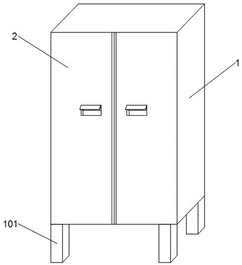
Referring to fig. 1-3, the present invention provides the following technical solutions: a multifunctional wardrobe comprises a wardrobe body 1 and a wardrobe door 2, wherein the wardrobe body 1 is hinged with the wardrobe door 2, the wardrobe body 1 comprises a long clothes area 3, a containing area 4, a clothes placing area 5 and a clothes drying area 6, the long clothes area 3 is positioned above the containing area 4, the clothes placing area 5 is positioned between the containing area 4 and the clothes drying area 6, the clothes drying area 6 is fixedly connected with a fan 601, a heating pipe 602, a clothes drying rod 603 and a bottom plate 604 which are sequentially distributed from top to bottom, the upper end surface of the bottom plate 604 is provided with a plurality of through holes which are uniformly distributed in a penetrating manner, the lower end surface of the bottom plate 604 is communicated with a collecting tank 605, the upper end surface and the lower end surface of the clothes placing area 5 are both fixedly connected with two rotating shafts 501, a rotating rod 502 is fixedly connected between the two rotating shafts 501, the outer wall of the rotating rod 502 is fixedly connected with a plurality of rotating plates 503, a humidity sensor 701, a dehumidifier 703 and an aromatic box 702 are sequentially arranged from left, the ventilation groove 7 is located below the humidity sensor 701.
In this embodiment: hang some wet clothing through at clothes-horse 603, start fan 601, make the wind that heating pipe 602 blew out fan 601 heat, and then can be with wet clothing fast drying, water that drops when wet clothing falls into the surface of bottom plate 604, collect in flowing into collecting vat 605 through the through-hole, but manual rotation bull stick 502 through pivot 501, make bull stick 502 drive rotating plate 503 rotate, and then can hang and get the clothing, can reach certain humidity as the humidity in the cabinet body 1 through humidity transducer 701, dehumidifier 703 just starts work, dehumidify the clothing in the cabinet body 1, reach the drying, peculiar smell can be got rid of to the clothing in the cabinet body 1 to fragrant box 702, some humidity in the cabinet body 1 can be distributed out to ventilation duct 7, can reach the effect with outside ventilation simultaneously.
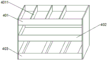
As the utility model discloses a technical optimization scheme, accomodate district 4 and include from last to the storage cabinet 401, receiver 402 and peg 403 that distribute down, the internally mounted of accomodating cabinet 401 has a plurality of baffles 4011, and the lower terminal surface intercommunication of accomodating district 4 has dry layer 404.
In this embodiment: the storage cabinet 401 is divided into a plurality of small storage cabinets 401 through the partition plates 4011, small clothes can be placed, the storage cabinet 402 can prevent trousers, the hanging rods 403 can hang the small clothes which are prone to wrinkling, the drying layer 404 can prevent the clothes from being damped, and therefore multifunctional use of the wardrobe is achieved.
As a technical optimization scheme of the utility model, put the lower terminal surface in clothing district 5 and install desk 506, a plurality of sliders 507 of lower terminal surface fixedly connected with of desk 506, desk 506 pass through slider 507 and cabinet body 1 sliding connection.
In this embodiment: by pulling the desk 506, the desk 506 is moved to the outside of the wardrobe body 1 under the action of the sliding block 507, so that the wardrobe can be used for working, and the multifunctional performance of the wardrobe is improved.
As a technical optimization scheme of the utility model, a plurality of rings 504 and a plurality of object placing grooves 505 that differ in size have been seted up respectively to a plurality of lower terminal surfaces that change board 503.
In this embodiment: clothes which are easy to wrinkle such as dress clothes can be hung through the hanging rings 504, small matching hanging pieces can be placed in the storage groove 505, and the practical flexibility of the wardrobe is improved.
As a technical optimization scheme of the utility model, guide rail 302 is all installed to the both sides of 3 inner walls in long clothing district, and sliding connection has between two guide rails 302 to hang clothing pole 301, and the sunglasses 201 is installed to the inner wall that is located left cabinet door 2.
In this embodiment: the clothes hanging rod 301 is manually pulled according to the length of the hung clothes, so that the clothes hanging rod 301 moves up and down in the guide rail 302, the clothes hanging rod can be automatically adjusted according to the requirement, and the clothes changing mirror 201 enables a user to have better clothes changing experience.
As a technical optimization scheme of the utility model, magnet piece 202 is all installed to the top of two cabinet door 2's inner wall, two and magnet piece 202 assorted magnet 203 of the positive fixedly connected with of the cabinet body 1, four supporting legs 101 are installed to the lower terminal surface of the cabinet body 1.
In this embodiment: the cabinet 1 and the cabinet door 2 can be closed by the attraction force of the magnet pieces 202 and the magnets 203, and the support legs 101 can support and stabilize the whole cabinet 1.
The utility model discloses a theory of operation and use flow: firstly, according to the length of the clothes, the clothes hanging rod 301 is manually pulled to enable the clothes hanging rod 301 to move up and down in the guide rail 302, and then the clothes hanging mirror 201 can be automatically adjusted according to requirements, so that a better clothes changing experience can be achieved for a clothes changing person, then the storage cabinet 401 is divided into a plurality of small storage cabinets 401 through the partition plates 4011, some small clothes can be prevented, the storage cabinet 402 can prevent some trousers, some small clothes which are easy to wrinkle can be hung through the hanging rods 403, the clothes can be prevented from being wetted by the drying layer 404, secondly, some wet clothes are hung on the clothes hanging rods 603, the fan 601 is started, the air blown out by the fan 601 is heated by the heating pipes 602, so that the wet clothes can be quickly dried, when water dropped from the wet clothes falls on the surface of the bottom plate 604 and flows into the collecting tank 605 through the through holes to be collected, then, the rotating rod 502 can be manually rotated through the rotating shaft 501, so that the rotating plate 503 is driven by the rotating rod, finally, the humidity sensor 701 can work when the humidity in the cabinet body 1 reaches a certain humidity, the dehumidifier 703 starts to work to dehumidify the clothes in the cabinet body 1, so as to achieve drying, the fragrance box 702 can remove peculiar smell from the clothes in the cabinet body 1, the ventilation groove 7 can distribute some humidity in the cabinet body 1, and meanwhile, the ventilation effect with the outside can be achieved.
The above description is only exemplary of the present invention and should not be construed as limiting the present invention, and any modifications, equivalents and improvements made within the spirit and principles of the present invention are intended to be included within the scope of the present invention.