CN213653024U - Fabric cutting and spreading device - Google Patents
Fabric cutting and spreading device Download PDFInfo
- Publication number
- CN213653024U CN213653024U CN202022507782.1U CN202022507782U CN213653024U CN 213653024 U CN213653024 U CN 213653024U CN 202022507782 U CN202022507782 U CN 202022507782U CN 213653024 U CN213653024 U CN 213653024U
- Authority
- CN
- China
- Prior art keywords
- threaded rod
- gear
- threaded
- fixed plate
- spreading device
- Prior art date
- Legal status (The legal status is an assumption and is not a legal conclusion. Google has not performed a legal analysis and makes no representation as to the accuracy of the status listed.)
- Expired - Fee Related
Links
- 239000004744 fabric Substances 0.000 title claims abstract description 46
- 238000005520 cutting process Methods 0.000 title claims description 11
- 238000003892 spreading Methods 0.000 title claims description 10
- 238000009434 installation Methods 0.000 claims abstract description 18
- 244000309464 bull Species 0.000 claims description 5
- 238000003466 welding Methods 0.000 claims description 3
- 230000009286 beneficial effect Effects 0.000 description 1
- 238000004519 manufacturing process Methods 0.000 description 1
- 238000000034 method Methods 0.000 description 1
Images


Landscapes
- Treatment Of Fiber Materials (AREA)
Abstract
The utility model discloses a granny rag device is tailor to surface fabric, including workstation, recess, installation piece, second fixed plate, cloth main part and second gear, the top of workstation is all seted up flutedly, and the internally mounted of recess has first fixed plate, first threaded rod is installed through the bearing in the inside of first fixed plate, and the outer wall of first threaded rod is provided with the installation piece, the second gear is installed to the one end of first threaded rod, the mounting panel is installed on the top of installation piece, and the top of mounting panel installs the second fixed plate, the slide rail is all installed to the lateral wall of second fixed plate one end. This granny rag device is tailor to surface fabric can drive the anchor clamps board through the slider in the inside of slide rail and carry out reciprocating motion through the second threaded rod when rotatory, is convenient for make anchor clamps board lifting movement come to press from both sides tight fixedly to the cloth main part, avoids operating personnel manual to take-up fixedly to the cloth.
Description
Technical Field
The utility model relates to a granny rag device technical field specifically is a granny rag device is tailor to surface fabric.
Background
The surface fabric needs to be tailor in process of production, when tailorring the cloth, needs straighten the cloth to be convenient for tailor the cloth, traditional surface fabric is tailor granny rag device and can satisfy people's user demand basically, but still has certain problem, and specific problem is as follows:
1. most fabric cutting and stretching devices in the market at present cannot fixedly stretch the fabric, and stretch the fabric manually, so that the labor intensity of operators is greatly increased by the stretching mode;
2. the granny rag device is tailor to most surface fabrics in the existing market, can't adjust, can't fix the flare-out to the cloth of different length, makes this granny rag device's practicality reduce.
SUMMERY OF THE UTILITY MODEL
An object of the utility model is to provide a granny rag device is tailor to solve the unable fixed flare-out to the cloth that proposes in the above-mentioned background art, all through artifical manual flare-out with unable regulation, the problem of can't fixing the flare-out to the cloth of different length.
In order to achieve the above object, the utility model provides a following technical scheme: a fabric cutting and spreading device comprises a workbench, grooves, mounting blocks, a second fixing plate, a fabric main body and a second gear, wherein the top end of the workbench is provided with the grooves, the first fixing plate is mounted inside the grooves, a first threaded rod is mounted inside the first fixing plate through a bearing, the outer wall of the first threaded rod is provided with the mounting blocks, one end of the first threaded rod is provided with the second gear, the top end of the mounting block is provided with a mounting plate, the top end of the mounting plate is provided with the second fixing plate, the side wall of one end of the second fixing plate is provided with a slide rail, a slide block is arranged inside the slide rail, one end of the slide block, which is far away from the slide rail, is provided with a clamp plate, the inside of the clamp plate is provided with a first threaded hole, the side wall of one end inside the workbench is provided with a rotating rod through a bearing, and the inside of mount pad is provided with the roller, the outer wall of roller is provided with the cloth main part.
Preferably, a second threaded hole is formed in the mounting block, and the second threaded hole is in threaded connection with the first threaded rod.
Preferably, the inside of first screw hole is provided with the second threaded rod, and the bottom of second threaded rod is connected with the mounting panel through the bearing.
Preferably, the top end of the second threaded rod is provided with a second turntable, and the outer wall of the second turntable is provided with anti-skid grains.
Preferably, a first gear is mounted at one end of the rotating rod, and the first gear and the second gear are meshed with each other.
Preferably, a first rotary table is installed at one end of the rotary rod, and the first rotary table and the rotary rod are of a welding integrated structure.
Compared with the prior art, the beneficial effects of the utility model are that:
1. by installing the mounting plate, the second fixing plate, the sliding rail, the sliding block, the clamp plate, the second threaded rod and the first threaded hole, the first threaded hole is in threaded connection with the second threaded rod, and the sliding rail and the sliding block are matched with each other, so that the second threaded rod can drive the clamp plate to reciprocate in the sliding rail through the sliding block while rotating, the clamp plate can be conveniently lifted and moved to clamp and fix the cloth main body, and an operator is prevented from manually tensioning and fixing the cloth;
2. the device is through installing first threaded rod simultaneously, the installation piece, first carousel, the bull stick, first gear, second gear and second screw hole, it is rotatory to drive bull stick and first gear through rotating first carousel, and through first gear and second gear intermeshing, make first gear can drive second gear and first threaded rod and rotate simultaneously in rotatory, and through second screw hole and first threaded rod threaded connection, make first threaded rod drive the installation piece and reciprocate to remove about in rotatory, thereby be convenient for operating personnel adjusts the distance of installation piece, make this granny rag device can strain different length cloth.
Drawings
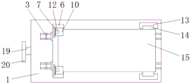
Fig. 1 is a schematic top view of the present invention;
FIG. 2 is a schematic top sectional view of the present invention;
FIG. 3 is a schematic sectional view of the front view of the present invention;
FIG. 4 is an enlarged view of the portion A of FIG. 3 according to the present invention;
fig. 5 is a schematic view of the cloth main body tensioning structure of the present invention.
In the figure: 1. a work table; 2. a groove; 3. a first fixing plate; 4. a first threaded rod; 5. mounting blocks; 6. mounting a plate; 7. a second fixing plate; 8. a slide rail; 9. a slider; 10. a clamp plate; 11. a first threaded hole; 12. a second threaded rod; 13. a mounting seat; 14. a roller; 15. a cloth main body; 16. a second threaded hole; 17. a first gear; 18. a second gear; 19. a rotating rod; 20. a first turntable; 21. a second turntable.
Detailed Description
The technical solutions in the embodiments of the present invention will be described clearly and completely with reference to the accompanying drawings in the embodiments of the present invention, and it is obvious that the described embodiments are only some embodiments of the present invention, not all embodiments. Based on the embodiments in the present invention, all other embodiments obtained by a person skilled in the art without creative work belong to the protection scope of the present invention.
Referring to fig. 1-5, the present invention provides an embodiment: a fabric cutting and spreading device comprises a workbench 1, grooves 2, mounting blocks 5, a second fixing plate 7, a fabric main body 15 and a second gear 18, wherein the grooves 2 are formed in the top end of the workbench 1, a first fixing plate 3 is mounted inside the grooves 2, a first threaded rod 4 is mounted inside the first fixing plate 3 through a bearing, and the mounting blocks 5 are arranged on the outer wall of the first threaded rod 4;
a second threaded hole 16 is formed in the mounting block 5, the second threaded hole 16 is in threaded connection with the first threaded rod 4, and the first threaded rod 4 is in threaded connection with the first threaded rod 4 through the second threaded hole 16, so that the mounting block 5 is driven to move left and right in a reciprocating manner while rotating;
a second gear 18 is installed at one end of the first threaded rod 4, an installation plate 6 is installed at the top end of the installation block 5, a second fixing plate 7 is installed at the top end of the installation plate 6, slide rails 8 are installed on the side walls of one end of the second fixing plate 7, a slide block 9 is arranged inside each slide rail 8, a clamp plate 10 is installed at one end, away from each slide rail 8, of each slide block 9, and a first threaded hole 11 is formed in each clamp plate 10;
a second threaded rod 12 is arranged inside the first threaded hole 11, and the bottom end of the second threaded rod 12 is connected with the mounting plate 6 through a bearing, so that the second threaded rod 12 can rotate inside the mounting plate 6;
the top end of the second threaded rod 12 is provided with a second rotary table 21, the outer wall of the second rotary table 21 is provided with anti-slip lines, and the anti-slip lines are arranged on the outer wall of the second rotary table 21, so that the phenomenon that an operator slips when rotating the second rotary table 21 is avoided;
a rotating rod 19 is arranged on the side wall of one end inside the workbench 1 through a bearing;
a first gear 17 is arranged at one end of the rotating rod 19, the first gear 17 is meshed with a second gear 18, and the first gear 17 is meshed with the second gear 18, so that the second gear 18 and the first threaded rod 4 can be driven to rotate simultaneously when the first gear 17 rotates;
a first rotating disc 20 is installed at one end of the rotating rod 19, and the first rotating disc 20 and the rotating rod 19 are of a welding integrated structure, so that the rotating rod 19 is driven to rotate simultaneously by rotating the first rotating disc 20;
an installation seat 13 is installed at one end of the top end of the workbench 1, a roller 14 is arranged inside the installation seat 13, and a cloth main body 15 is arranged on the outer wall of the roller 14.
The working principle is as follows: when the fabric cutting and spreading device is used, firstly, an operator pulls the fabric main body 15 to place the fabric main body 15 at the top end of the mounting plate 6, then the second rotary table 21 is rotated to drive the second threaded rod 12 to rotate, the first threaded hole 11 is in threaded connection with the second threaded rod 12, and the slide rail 8 is matched with the slide block 9, so that the second threaded rod 12 can drive the clamp plate 10 to reciprocate in the slide rail 8 through the slide block 9 while rotating, the clamp plate 10 can conveniently move up and down to clamp and fix the fabric main body 15, and the operator is prevented from manually tensioning and fixing the fabric;
after cloth main part 15 is fixed, drive bull stick 19 and first gear 17 simultaneously through rotating first carousel 20 and rotate, and through first gear 17 and 18 intermeshing of second gear, make first gear 17 can drive second gear 18 and first threaded rod 4 simultaneously rotate in the rotatory, and through second screw hole 16 and 4 threaded connection of first threaded rod, make first threaded rod 4 drive installation piece 5 and reciprocate when rotatory and control about, thereby be convenient for operating personnel adjusts the distance of installation piece 5, make this granny rag device can strain different length cloth, it is above the utility model discloses a whole theory of operation.
It is obvious to a person skilled in the art that the invention is not restricted to details of the above-described exemplary embodiments, but that it can be implemented in other specific forms without departing from the spirit or essential characteristics of the invention. The present embodiments are therefore to be considered in all respects as illustrative and not restrictive, the scope of the invention being indicated by the appended claims rather than by the foregoing description, and all changes which come within the meaning and range of equivalency of the claims are therefore intended to be embraced therein. Any reference sign in a claim should not be construed as limiting the claim concerned.
Claims (6)
1. The utility model provides a granny rag device is tailor to surface fabric, includes workstation (1), recess (2), installation piece (5), second fixed plate (7), cloth main part (15) and second gear (18), its characterized in that: the top end of the workbench (1) is provided with grooves (2), a first fixing plate (3) is arranged inside the grooves (2), a first threaded rod (4) is arranged inside the first fixing plate (3) through a bearing, an installation block (5) is arranged on the outer wall of the first threaded rod (4), a second gear (18) is arranged at one end of the first threaded rod (4), an installation plate (6) is arranged at the top end of the installation block (5), a second fixing plate (7) is arranged at the top end of the installation plate (6), slide rails (8) are arranged on the side wall of one end of the second fixing plate (7), a slide block (9) is arranged inside the slide rails (8), a clamp plate (10) is arranged at one end, far away from the slide rails (8), of the slide block (9), a first threaded hole (11) is formed inside the clamp plate (10), a rotating rod (19) is arranged on the side wall of one end inside the workbench (1) through a, a mounting seat (13) is installed at one end of the top end of the workbench (1), a roller (14) is arranged inside the mounting seat (13), and a cloth main body (15) is arranged on the outer wall of the roller (14).
2. A fabric cutting and spreading device according to claim 1, which is characterized in that: and a second threaded hole (16) is formed in the mounting block (5), and the second threaded hole (16) is in threaded connection with the first threaded rod (4).
3. A fabric cutting and spreading device according to claim 1, which is characterized in that: the inside of first screw hole (11) is provided with second threaded rod (12), and the bottom of second threaded rod (12) is connected with mounting panel (6) through the bearing.
4. A fabric cutting and spreading device according to claim 3, which is characterized in that: and a second turntable (21) is installed at the top end of the second threaded rod (12), and anti-skid grains are arranged on the outer wall of the second turntable (21).
5. A fabric cutting and spreading device according to claim 1, which is characterized in that: a first gear (17) is installed at one end of the rotating rod (19), and the first gear (17) is meshed with a second gear (18).
6. A fabric cutting and spreading device according to claim 1, which is characterized in that: first carousel (20) is installed to the one end of bull stick (19), and first carousel (20) and bull stick (19) are welding integral structure.
Priority Applications (1)
| Application Number | Priority Date | Filing Date | Title |
|---|---|---|---|
| CN202022507782.1U CN213653024U (en) | 2020-11-03 | 2020-11-03 | Fabric cutting and spreading device |
Applications Claiming Priority (1)
| Application Number | Priority Date | Filing Date | Title |
|---|---|---|---|
| CN202022507782.1U CN213653024U (en) | 2020-11-03 | 2020-11-03 | Fabric cutting and spreading device |
Publications (1)
| Publication Number | Publication Date |
|---|---|
| CN213653024U true CN213653024U (en) | 2021-07-09 |
Family
ID=76705230
Family Applications (1)
| Application Number | Title | Priority Date | Filing Date |
|---|---|---|---|
| CN202022507782.1U Expired - Fee Related CN213653024U (en) | 2020-11-03 | 2020-11-03 | Fabric cutting and spreading device |
Country Status (1)
| Country | Link |
|---|---|
| CN (1) | CN213653024U (en) |
Cited By (2)
| Publication number | Priority date | Publication date | Assignee | Title |
|---|---|---|---|---|
| CN118292255A (en) * | 2024-05-13 | 2024-07-05 | 晋江森拓领服装有限责任公司 | A clothing cutting machine with high cutting precision |
| CN119510200A (en) * | 2024-10-14 | 2025-02-25 | 镇江恒创纺织机械有限公司 | A textile machinery component performance testing device and method |
-
2020
- 2020-11-03 CN CN202022507782.1U patent/CN213653024U/en not_active Expired - Fee Related
Cited By (2)
| Publication number | Priority date | Publication date | Assignee | Title |
|---|---|---|---|---|
| CN118292255A (en) * | 2024-05-13 | 2024-07-05 | 晋江森拓领服装有限责任公司 | A clothing cutting machine with high cutting precision |
| CN119510200A (en) * | 2024-10-14 | 2025-02-25 | 镇江恒创纺织机械有限公司 | A textile machinery component performance testing device and method |
Similar Documents
| Publication | Publication Date | Title |
|---|---|---|
| CN215325983U (en) | Tufting machine base cloth deviation correcting device | |
| CN214640728U (en) | Civil air defense door frame channel steel cutting device | |
| CN211277798U (en) | Device is used in processing of new energy automobile electric cabinet | |
| CN212741146U (en) | Semi-automatic cutting device of super large super thick glass | |
| CN213681451U (en) | Device is tailor fast to cloth for textile production | |
| CN214053179U (en) | Section bar stretching and straightening device | |
| CN215251640U (en) | Cloth fixing device of embroidery machine | |
| CN110539580A (en) | Leveling mechanism for attaching wall cloth | |
| CN214024302U (en) | A fixture for welding display sheet metal shell | |
| CN221318677U (en) | Automatic tiling machine of regulation | |
| CN119036247B (en) | A curtain wall cutting and edging device for curtain wall decoration engineering | |
| CN211759433U (en) | Welding device for producing vehicle outlet box | |
| CN221895284U (en) | A buttonhole machine for garment processing | |
| CN221421434U (en) | Curtain cloth weaving hole stretching device | |
| CN112935971A (en) | Processing machine for parts of electronic pattern machine | |
| CN221480327U (en) | Garment materials ironing device | |
| CN201092725Y (en) | Grinding device for dustfree wall surface | |
| CN223706083U (en) | Polyester knitting grey cloth processing shearing mechanism | |
| CN220024263U (en) | Quick installation device of clothing trim | |
| CN212834545U (en) | Cloth tightening device for coated cloth | |
| CN221165795U (en) | Mounting bracket for power engineering | |
| CN215704918U (en) | Glass silk screen printing machine of ability automatically regulated printing pressure | |
| CN218363431U (en) | A compress tightly fixing device fast for machining | |
| CN220246531U (en) | Edge cutter is used in textile fabric processing | |
| CN219583751U (en) | Heat transfer screen cloth mechanism of stretching straight |
Legal Events
| Date | Code | Title | Description |
|---|---|---|---|
| GR01 | Patent grant | ||
| GR01 | Patent grant | ||
| CF01 | Termination of patent right due to non-payment of annual fee |
Granted publication date: 20210709 |
|
| CF01 | Termination of patent right due to non-payment of annual fee |