CN213647748U - Large-scale cutting machine of irregular sponge - Google Patents
Large-scale cutting machine of irregular sponge Download PDFInfo
- Publication number
- CN213647748U CN213647748U CN202022756398.5U CN202022756398U CN213647748U CN 213647748 U CN213647748 U CN 213647748U CN 202022756398 U CN202022756398 U CN 202022756398U CN 213647748 U CN213647748 U CN 213647748U
- Authority
- CN
- China
- Prior art keywords
- fixing frame
- sides
- workbench
- cutting machine
- carrying platform
- Prior art date
- Legal status (The legal status is an assumption and is not a legal conclusion. Google has not performed a legal analysis and makes no representation as to the accuracy of the status listed.)
- Expired - Fee Related
Links
- 238000005520 cutting process Methods 0.000 title claims abstract description 37
- 230000001788 irregular Effects 0.000 title claims abstract description 14
- 230000007246 mechanism Effects 0.000 claims abstract description 13
- 238000004519 manufacturing process Methods 0.000 abstract description 3
- 206010066054 Dysmorphism Diseases 0.000 description 2
- 230000002547 anomalous effect Effects 0.000 description 2
- 230000009286 beneficial effect Effects 0.000 description 1
- 230000005540 biological transmission Effects 0.000 description 1
- 230000007547 defect Effects 0.000 description 1
- 238000010586 diagram Methods 0.000 description 1
- 238000000034 method Methods 0.000 description 1
Images
Landscapes
- Processing Of Stones Or Stones Resemblance Materials (AREA)
Abstract
The utility model relates to the technical field of sponge cutting machines, in particular to a large irregular sponge cutting machine, which comprises a cutting mechanism, a workbench and a control cabinet, wherein the workbench is arranged at the bottom of the cutting mechanism, guide rails are arranged at both sides of the top of the workbench, a carrying platform is connected on the guide rails in a sliding way, a motor is fixedly connected on the end surface of the workbench, the sponge is clamped and fixed by a first fixing frame and a second fixing frame which are arranged, the clamping range is larger and is not limited to the width of the carrying platform because the first fixing frame and the second fixing frame can move outwards or inwards, and a user can conveniently observe the clamping force of the first fixing frame by a pressure sensor arranged, thereby the user can conveniently adjust the expansion amount of an electric telescopic rod, the utility model has reasonable design and low cost, is worthy of enterprise production and popularization to the society.
Description
Technical Field
The utility model relates to a sponge cutting machine technical field especially relates to a large-scale cutting machine of irregular sponge.
Background
Chinese patent publication No. CN201783980U discloses a numerical control special-shaped sponge cutting machine, which comprises a frame and a conveyor belt arranged at the bottom of the frame, wherein three groups of vibration cutting mechanisms are arranged on the frame, and each vibration cutting mechanism is formed by connecting a vibration knife between a pair of vibration boxes; the first group of vibrating knives are transversely arranged; second, three vertical settings of group's vibration sword, and be connected through slide rail, slider between three vibration cutting mechanism's of group each vibration casees and the frame for the vibration case can be followed the frame side post respectively, the upper and lower crossbeam removes the position change that realizes the vibration sword, adopts the utility model discloses when the multi-functional sponge cutting machine of structure cuts, can select from horizontal and vertical cutting piecemeal that carries out the sponge according to actual requirement, when repairing sponge both sides deckle edge, only need adopt two sets of vertical vibration cutters simultaneously to go on, need not to move again and go on to special deckle edge cutting machine, save and remove the time of moving the sponge from top to bottom, improved production efficiency, reduced workman intensity of labour.
Although this dysmorphism sponge cutting machine can effectually carry out anomalous special-shaped processing to the sponge, discover during the use not to the fixed of sponge in its frame, consequently in the cutting process, the change of position very easily takes place for the sponge to lead to cutting error, extravagant material.
SUMMERY OF THE UTILITY MODEL
The utility model aims at solving the defects that the sponge is not fixed and the like in the prior art and providing a large-scale cutting machine for irregular sponge.
In order to achieve the above purpose, the utility model adopts the following technical scheme:
the large irregular sponge cutting machine comprises a cutting mechanism, a workbench and a control cabinet, wherein the workbench is arranged at the bottom of the cutting mechanism, guide rails are arranged on two sides of the top of the workbench, a carrying platform is connected on the guide rails in a sliding manner, a motor is fixedly connected to the end surface of the workbench, a groove is formed in the middle of the workbench, an output shaft of the motor penetrates through the end surface of the workbench and is fixedly connected with a screw rod, one end, away from the motor, of the screw rod is rotatably connected to the inner wall of the groove through a bearing, the screw rod is in threaded connection with the carrying platform, mounting grooves are formed in two sides of the top of the carrying platform, a cover plate is arranged at the tops of the mounting grooves, a first fixing frame and a second fixing frame are movably inserted into two sides of the mounting grooves respectively, the length of the first fixing frame is larger than that of the second fixing frame, the bottom of the two sets of mounting grooves is provided with gears at intervals, racks at the bottoms of the first fixing frame and the second fixing frame are respectively arranged on two sides of the gears and meshed with the gears, supporting plates are fixedly connected to two sides of the first fixing frame, electric push rods are arranged on two sides of the top of the carrying platform, output shafts of the electric push rods are fixedly connected with the supporting plates, and the electric push rods are electrically connected with an external power supply through wires.
Preferably, a drag chain is arranged in the groove along the length direction, a lead of the electric push rod is arranged in the drag chain, and two ends of the drag chain are respectively arranged at the bottom of the groove and the end surface of the carrier.
Preferably, the cover plate is fixedly installed at the top of the carrying platform through bolts, openings of the first fixing frame and the second fixing frame are contained in two sides of the top of the cover plate, and rollers abutted to the racks are arranged on two sides of the bottom of the cover plate.
Preferably, pressure sensors are arranged on two sides of the first fixing frame and electrically connected with the control cabinet.
The utility model provides a pair of large-scale cutting machine of irregular sponge, beneficial effect lies in: the utility model discloses a first mount and the second mount that set up come to carry out the centre gripping to the sponge fixed, because first mount and second mount can outwards or inside removal, therefore its centre gripping scope is bigger, and not limited to the width of microscope carrier, the clamping force degree of first mount is observed through the pressure sensor person of facilitating the use who sets up to the person of facilitating the use adjusts electric telescopic handle's flexible volume, this utility model relates to a rationally, and the cost is not high, be worth enterprise's production and popularize to the society.
Drawings
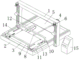
Fig. 1 is a schematic structural view of a large irregular sponge cutting machine provided by the present invention;
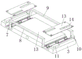
fig. 2 is the structural schematic diagram of the large-scale cutting machine carrier for irregular sponge provided by the utility model.
In the figure: 1. a cutting mechanism; 2. a work table; 3. a stage; 4. a motor; 5. a groove; 6. a screw; 7. mounting grooves; 8. a first fixing frame; 9. a second fixing frame; 10. a support plate; 11. an electric push rod; 12. a drag chain; 13. a cover plate; 14. an opening; 15. a control cabinet.
Detailed Description
The technical solutions in the embodiments of the present invention will be described clearly and completely with reference to the accompanying drawings in the embodiments of the present invention, and it is obvious that the described embodiments are only some embodiments of the present invention, not all embodiments.
Referring to fig. 1-2, a large-scale irregular sponge cutting machine comprises a cutting mechanism 1, a workbench 2 and a control cabinet 15, wherein the workbench 2 is arranged at the bottom of the cutting mechanism 1, guide rails are arranged on both sides of the top of the workbench 2, a carrier 3 is connected on the guide rails in a sliding manner, rollers can be arranged on the carrier 3, so that the sponge can be conveniently moved when being fixed, a motor 4 is fixedly connected onto the end surface of the workbench 2, a groove 5 is arranged in the middle of the workbench 2, an output shaft of the motor 4 penetrates through the end surface of the workbench 2 and is fixedly connected with a screw 6, one end of the screw 6 far away from the motor 4 is rotatably connected onto the inner wall of the groove 5 through a bearing, the screw 6 is in threaded connection with the carrier 3, mounting grooves 7 are arranged on both sides of the top of the carrier 3, a cover plate 13 is arranged on the top of the mounting grooves 7, a, and the length of first mount 8 is greater than the length of second mount 9, the bottom both sides of first mount 8 and second mount 9 all are provided with the rack, the bottom interval of two sets of mounting grooves 7 is provided with the gear, the rack of the bottom of first mount 8 and second mount 9 sets up respectively in the both sides of gear and with gear engagement, the both sides fixedly connected with backup pad 10 of first mount 8, the top both sides of microscope carrier 3 all are provided with electric putter 11, and electric putter 11's output shaft and backup pad 10 fixed connection, electric putter 11 passes through wire and external power source electric connection.
The inside of recess 5 is provided with tow chain 12 along length direction, and electric putter 11's wire setting is in the inside of tow chain 12, and the both ends of tow chain 12 are installed respectively on the bottom of recess 5 and the terminal surface of microscope carrier 3, and the condition of knoing takes place to twine for the wire of electric putter 11 is avoided to the tow chain 12 that sets up.
The cover plate 13 is fixedly installed at the top of the carrying platform 3 through bolts, openings 14 of the first fixing frame 8 and the second fixing frame 9 are contained in the two sides of the top of the cover plate 13, rollers abutted to the racks are arranged on the two sides of the bottom of the cover plate 13, the racks are abutted and fixed through the cover plate 13, and the openings 14 are convenient for the first fixing frame 8 and the second fixing frame 9 to move inwards to clamp the sponge with small size.
Pressure sensor is all provided with in the both sides of first mount 8, and pressure sensor and 15 electric connection of switch board, and pressure sensor person of facilitating the use observes the centre gripping dynamics of first mount 8 and second mount 9 to the sponge to person of facilitating the use adjusts electric putter 11's flexible volume.
A working mode; the during operation, place the sponge that will process on microscope carrier 3, at this moment, electric putter 11 can be opened to the user, electric putter 11 drives first mount 8 and removes, first mount 8 is through the rack of bottom both sides and the meshing transmission of gear, make second mount 9 produce relative motion, thereby it is fixed to realize that first mount 8 and second mount 9 come to carry out the centre gripping to the both sides of sponge, motor 4 can be opened to fixed completion back user, motor 4 passes through 6 drive microscope carrier 3 removals of screw rod, make the sponge carry out cutting mechanism 1 and carry out anomalous dysmorphism processing, and is simple in operation.
The above, only be the concrete implementation of the preferred embodiment of the present invention, but the protection scope of the present invention is not limited thereto, and any person skilled in the art is in the technical scope of the present invention, according to the technical solution of the present invention and the utility model, the concept of which is equivalent to replace or change, should be covered within the protection scope of the present invention.
Claims (4)
1. The utility model provides a large-scale cutting machine of irregular sponge, includes cutting mechanism (1), workstation (2) and switch board (15), its characterized in that: the cutting machine is characterized in that the workbench (2) is arranged at the bottom of the cutting mechanism (1), guide rails are arranged on two sides of the top of the workbench (2), a carrying platform (3) is connected onto the guide rails in a sliding manner, a motor (4) is fixedly connected onto the end face of the workbench (2), a groove (5) is formed in the middle of the workbench (2), an output shaft of the motor (4) penetrates through the end face of the workbench (2) and is fixedly connected with a screw rod (6), one end, far away from the motor (4), of the screw rod (6) is rotatably connected onto the inner wall of the groove (5) through a bearing, the screw rod (6) is in threaded connection with the carrying platform (3), mounting grooves (7) are arranged on two sides of the top of the carrying platform (3), a cover plate (13) is arranged on the top of each mounting groove (7), a first fixing frame (8) and a second fixing frame (9, and the length of the first fixing frame (8) is greater than that of the second fixing frame (9), racks are arranged on two sides of the bottoms of the first fixing frame (8) and the second fixing frame (9), two sets of gears are arranged at the bottom of the mounting groove (7) at intervals, the racks on the bottoms of the first fixing frame (8) and the second fixing frame (9) are respectively arranged on two sides of the gears and are meshed with the gears, supporting plates (10) are fixedly connected to two sides of the first fixing frame (8), electric push rods (11) are arranged on two sides of the top of the carrying platform (3), output shafts of the electric push rods (11) are fixedly connected with the supporting plates (10), and the electric push rods (11) are electrically connected with an external power supply through wires.
2. The large irregular sponge cutting machine according to claim 1, wherein: the inner part of the groove (5) is provided with a drag chain (12) along the length direction, a lead of the electric push rod (11) is arranged in the drag chain (12), and two ends of the drag chain (12) are respectively arranged at the bottom of the groove (5) and the end surface of the carrying platform (3).
3. The large irregular sponge cutting machine according to claim 1, wherein: the cover plate (13) is fixedly installed at the top of the carrying platform (3) through bolts, openings (14) of the first fixing frame (8) and the second fixing frame (9) are contained in two sides of the top of the cover plate (13), and rollers abutted to the racks are arranged on two sides of the bottom of the cover plate (13).
4. The large irregular sponge cutting machine according to claim 1, wherein: and pressure sensors are arranged on two sides of the first fixing frame (8) and are electrically connected with the control cabinet (15).
Priority Applications (1)
| Application Number | Priority Date | Filing Date | Title |
|---|---|---|---|
| CN202022756398.5U CN213647748U (en) | 2020-11-25 | 2020-11-25 | Large-scale cutting machine of irregular sponge |
Applications Claiming Priority (1)
| Application Number | Priority Date | Filing Date | Title |
|---|---|---|---|
| CN202022756398.5U CN213647748U (en) | 2020-11-25 | 2020-11-25 | Large-scale cutting machine of irregular sponge |
Publications (1)
| Publication Number | Publication Date |
|---|---|
| CN213647748U true CN213647748U (en) | 2021-07-09 |
Family
ID=76689452
Family Applications (1)
| Application Number | Title | Priority Date | Filing Date |
|---|---|---|---|
| CN202022756398.5U Expired - Fee Related CN213647748U (en) | 2020-11-25 | 2020-11-25 | Large-scale cutting machine of irregular sponge |
Country Status (1)
| Country | Link |
|---|---|
| CN (1) | CN213647748U (en) |
Cited By (2)
| Publication number | Priority date | Publication date | Assignee | Title |
|---|---|---|---|---|
| CN114670266A (en) * | 2022-03-29 | 2022-06-28 | 南通荣日纺织科技有限公司 | Sponge piece cutting machine |
| CN115107092A (en) * | 2022-06-29 | 2022-09-27 | 兰剑智能科技股份有限公司 | Sponge strip blocking device |
-
2020
- 2020-11-25 CN CN202022756398.5U patent/CN213647748U/en not_active Expired - Fee Related
Cited By (3)
| Publication number | Priority date | Publication date | Assignee | Title |
|---|---|---|---|---|
| CN114670266A (en) * | 2022-03-29 | 2022-06-28 | 南通荣日纺织科技有限公司 | Sponge piece cutting machine |
| CN115107092A (en) * | 2022-06-29 | 2022-09-27 | 兰剑智能科技股份有限公司 | Sponge strip blocking device |
| CN115107092B (en) * | 2022-06-29 | 2024-03-19 | 兰剑智能科技股份有限公司 | Sponge strip blocking device |
Similar Documents
| Publication | Publication Date | Title |
|---|---|---|
| CN211305228U (en) | Industrial laser device for cutting | |
| CN215749648U (en) | Sliding table saw convenient to adjust and used for wood processing | |
| CN214264792U (en) | Pneumatic centre gripping frock of dysmorphism piece | |
| CN110552190A (en) | Clothing cutting system | |
| CN216633623U (en) | Wire cutting machine is used in aluminum products production | |
| CN107706835B (en) | A kind of cable laser cutting peeling equipment | |
| CN219465100U (en) | Processing cutting equipment for hollow plastic plate | |
| CN215786956U (en) | Light planer-type milling machine of base self-cleaning formula | |
| CN218802648U (en) | Machine parts cutting process device | |
| CN210916745U (en) | Clothing cutting system | |
| CN220838285U (en) | Steering gear rack double-sided tapping machine tool | |
| CN214815696U (en) | Dust removal and waste collection device of laser cutting machine | |
| CN212954865U (en) | A glass-cutting machine for processing of on-vehicle bar screen | |
| CN212558386U (en) | Material stripping device | |
| CN210504948U (en) | Drum type cloth slicing and strip cutting machine | |
| CN217144054U (en) | Double-convolution paper cutter with dust removal function | |
| CN213672301U (en) | Electric spark wire-electrode cutting machine tool | |
| CN217536472U (en) | A cutting equipment for surface fabric processing | |
| CN222971165U (en) | Linear cutting equipment for injection mold machining | |
| CN220840656U (en) | Furniture board fluting device | |
| CN219854892U (en) | Round pressing and cutting machine | |
| CN219379396U (en) | Automatic feeding and cutting equipment for spectacle frame | |
| CN218365252U (en) | Workpiece supporting table of water cutting machine | |
| CN112318754A (en) | Multi-wire cutting machine for processing solar cell panel | |
| CN221271424U (en) | Double-sided planing device |
Legal Events
| Date | Code | Title | Description |
|---|---|---|---|
| GR01 | Patent grant | ||
| GR01 | Patent grant | ||
| CF01 | Termination of patent right due to non-payment of annual fee | ||
| CF01 | Termination of patent right due to non-payment of annual fee |
Granted publication date: 20210709 |