Filter bag body and head-bottom needle eye film pasting and sealing integrated machine
Technical Field
The utility model relates to a filter bag processing equipment technical field specifically is a sealed all-in-one of needle eye pad pasting at bottom of filter bag body and head.
Background
The filter bag has excellent chemical property stability and heat resistance, is a representative of the highest performance in the filter material industry, is also a variety with the highest performance in all common filter materials, and achieves higher levels in the aspects of filter efficiency, filter precision and the like. Commonly used filter materials are PE, PP, PTFE, PMIA, NMO and the like, a filter bag is a key part in the operation process of a bag type dust collector, and a cylindrical filter bag is usually vertically hung in the dust collector. The fabric and design of the filter bag should seek high-efficiency filtration, easy dust stripping and durable effect as much as possible. In pulse and air box type pulse dust collector, dust is attached to the outer surface of the filter bag. When the dust-containing gas passes through the dust remover, the dust is trapped on the outer surface of the filter bag, and the clean gas enters the interior of the filter bag through the filter material. The cage inside the bag serves to support the bag against collapse and at the same time it facilitates the removal and redistribution of the dust cake.
At present, in the production and sealing process of a filter bag, a bag body and a head bottom needle eye of the filter bag need to be subjected to film pasting sealing, most of the filter bag needs to be subjected to film pasting sealing through manual work, the time is too consumed in the process, and the labor cost is higher.
SUMMERY OF THE UTILITY MODEL
An object of the utility model is to provide a filter bag body and sealed all-in-one of needle eye pad pasting at bottom of head to solve the problem that provides among the above-mentioned background art.
In order to achieve the above object, the utility model provides a following technical scheme: a filter bag body and head-bottom needle eye pad pasting sealing integrated machine comprises a workbench, wherein a mounting plate is fixedly mounted at the left end of the upper surface of the workbench, a hydraulic telescopic cylinder is fixedly mounted at the right side of the mounting plate, a push plate is fixedly mounted at the right end of the hydraulic telescopic cylinder, a spring clamp is fixedly mounted at the right side of the push plate, a connecting plate is fixedly connected with the rear end of the upper surface of the workbench, a placing plate is fixedly mounted at the middle part of the connecting plate, a first fixing plate is fixedly mounted at the upper end of the front of the connecting plate, a first telescopic cylinder is fixedly mounted at the bottom of the first fixing plate, a pressing device is fixedly mounted at the bottom end of the first telescopic cylinder, a rubber pressing wheel is rotatably connected inside the pressing device, a rubber roller is rotatably connected at the middle part of the front of the connecting plate, a second fixing plate is fixedly mounted at the right, the cutting device comprises a cutting device body, a first fixing plate, a first rubber pressing roller, a second fixing plate, a first return spring, a press plate, a cutter, a first fixing plate, a first film sticking box, a servo motor, a second telescopic cylinder, a support plate, a second cutting device body and a second film sticking box.
Preferably, the number of the sliding grooves is 2, the sliding grooves are respectively arranged on the left wall and the right wall in the first cutter device, the return springs are fixedly arranged in the sliding grooves, and the top ends of the two return springs are respectively and fixedly arranged at the bottoms of the left end and the right end of the pressing plate.
Preferably, the upper surface of workstation is seted up flutedly, and the inside fixed mounting of recess has the flexible cylinder of second, and the top fixed mounting of the flexible cylinder of second has the fixed block, and the back fixed mounting of fixed block has the bearing, and the bearing rotates and is connected with the rubber compression roller.
Preferably, the back fixed mounting of connecting plate has the board of accepting, and the last fixed surface of accepting the board installs servo motor, and servo motor's left end pivot is rotated and is connected with the rubber roller, and the bottom right-hand member fixed mounting who accepts the board has the bracing piece, and the other end of bracing piece is installed at the back of connecting plate.
Preferably, the inner front wall and the inner rear wall of the abutting device are respectively and fixedly provided with a bearing, and the inner sides of the two bearings are respectively and rotatably connected with the front end and the rear end of the rubber pinch roller.
Compared with the prior art, the utility model provides a sealed all-in-one of needle eye pad pasting at bottom of filter bag body and head possesses following beneficial effect:
the integrated machine for sticking the film on the bag body and the needle hole at the bottom of the filter bag comprises a filter bag, a rubber roller, a first telescopic cylinder, a servo motor, a cutter device, a hydraulic telescopic rod, a second telescopic cylinder, a spring clamp, a filter bag head, a second film sticking device, a rubber roller, a rubber film sticking head, a second film sticking roller, a hydraulic telescopic rod, a hydraulic telescopic cylinder, a hydraulic telescopic rod, a first telescopic cylinder, a second telescopic cylinder, a first film sticking head, a second film sticking head, a third telescopic rod, the cost of manual film sticking is reduced.
Drawings
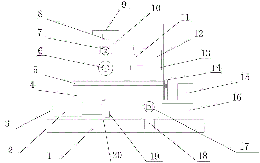
FIG. 1 is a schematic side sectional view of the present invention;
FIG. 2 is a schematic view of the front cross-sectional structure of the present invention;
fig. 3 is a schematic view of the section structure of the cutter device of the present invention.
In the figure: the cutting machine comprises a workbench, a hydraulic telescopic cylinder 2, a mounting plate 3, a connecting plate 4, a placing plate 5, a rubber roller 6, a rubber pressing wheel 7, a first telescopic cylinder 8, a first fixing plate 9, a first abutting device 10, a first cutter device 11, a first film box 12, a second fixing plate 13, a second cutter device 14, a second film box 15, a supporting plate 16, a rubber pressing roller 17, a second telescopic cylinder 18, a spring clamp 19, a push plate 20, a servo motor 21, a sliding chute 22, a return spring 23, a pressing plate 24 and a cutter 25.
Detailed Description
The technical solutions in the embodiments of the present invention will be described clearly and completely with reference to the accompanying drawings in the embodiments of the present invention, and it is obvious that the described embodiments are only some embodiments of the present invention, not all embodiments. Based on the embodiments in the present invention, all other embodiments obtained by a person skilled in the art without creative work belong to the protection scope of the present invention.
Referring to fig. 1-3, the present invention provides a technical solution: a filter bag body and head and bottom needle eye pad pasting and sealing integrated machine comprises a workbench 1, a mounting plate 3 is fixedly mounted at the left end of the upper surface of the workbench 1, a hydraulic telescopic cylinder 2 is fixedly mounted at the right side of the mounting plate 3, a push plate 20 is fixedly mounted at the right end of the hydraulic telescopic cylinder 2, a spring clamp 19 is fixedly mounted at the right side of the push plate 20, a connecting plate 4 is fixedly connected with the rear end of the upper surface of the workbench 1, a placing plate 5 is fixedly mounted at the middle part of the connecting plate 4, a first fixing plate 9 is fixedly mounted at the upper end of the front surface of the connecting plate 4, a first telescopic cylinder 8 is fixedly mounted at the bottom of the first fixing plate 9, a pressure resisting device 10 is fixedly mounted at the bottom end of the first telescopic cylinder 8, a rubber pinch roller 7 is rotatably connected inside the pressure resisting device 10, bearings are respectively fixedly mounted on the front wall and the rear wall inside of, the middle part of the front of the connecting plate 4 is rotatably connected with a rubber roller 6, the right side of the front of the connecting plate 4 is fixedly provided with a second fixing plate 13, the left end of the upper surface of the second fixing plate 13 is fixedly provided with a first cutter device 11, the left wall of the inner part of the first cutter device 11 is provided with a chute 22, the inner part of the chute 22 is fixedly provided with a return spring 23, the top end of the return spring 23 is fixedly provided with a pressing plate 24, the bottom of the pressing plate 24 is fixedly provided with a cutter 25, the number of the chutes 22 is 2, the chutes 22 are respectively arranged on the left wall and the right wall of the inner part of the first cutter device 11, the inner part of each chute is fixedly provided with a return spring, the top ends of the two return springs are respectively and fixedly arranged at the bottoms of the left end and the right end of the pressing, a servo motor 21 is fixedly arranged on the upper surface of the bearing plate, a rubber roller 6 is rotatably connected with a rotating shaft at the left end of the servo motor 21, a filter bag is sleeved on the rubber roller 6, a film in a film sticking box I12 is stuck to a needle hole of a filter bag head, a first telescopic cylinder 8 is started to press a rubber pressing wheel 7 to the upper surface of the film, the servo motor 21 is started to drive the rubber roller 6 to rotate, the film is stuck under the pressure of the rubber pressing wheel 7, the film is cut off by a cutter device I11 after the film sticking is finished, a supporting rod is fixedly arranged at the right end of the bottom of the bearing plate, the other end of the supporting rod is arranged on the back surface of a connecting plate 4, a second telescopic cylinder 18 is fixedly arranged on the upper surface of the workbench 1, a rubber pressing roller 17 is rotatably connected with the top end of the second telescopic cylinder 18, a groove is formed in the upper surface of the workbench 1, a second telescopic cylinder, a bearing is fixedly arranged on the back of the fixed block, the bearing is rotatably connected with a rubber compression roller 17, a supporting plate 16 is fixedly arranged on the upper surface of the workbench 1, a cutter device II 14 is fixedly arranged on the left end of the upper surface of the supporting plate 16, a film sticking box II 15 is fixedly arranged on the right end of the upper surface of the supporting plate 16, a filter bag body and a head-bottom needle eye film sticking and sealing integrated machine are fixedly arranged, then the filter bag is taken down, the spring clamp 19 clamps the filter bag head, the adhesive film in the adhesive film box II 15 is adhered on the needle hole of the filter bag body, the second telescopic cylinder 18 is started, the rubber compression roller 17 presses the filter bag, then the hydraulic telescopic rod 2 is started to retract the telescopic rod of the hydraulic telescopic cylinder, the spring clamp 19 is driven to move leftwards, the filter bag moves along, after the film sticking is completed, the second cutter device 14 is used for cutting off the sticking film, so that the working efficiency of sticking film sealing of the filter bag is improved, manual sticking film is avoided, and the cost of manual sticking film is reduced.
In the actual operation process, when the device is used, the filter bag is sleeved on the rubber roller 6, the pad pasting in the pad pasting box I12 is pasted on the needle eye of the filter bag head, the first telescopic cylinder 8 is started to press the rubber pressing wheel 7 against the upper surface of the pad pasting, the servo motor 21 is started to drive the rubber roller 6 to rotate, the film is pasted under the pressure of the rubber pinch roller 7, the film is cut off by a cutter device I11 after the film is pasted, then the filter bag is taken down, the spring clamp 19 clamps the filter bag head, the adhesive film in the adhesive film box II 15 is adhered on the needle hole of the filter bag body, the second telescopic cylinder 18 is started, the rubber compression roller 17 presses the filter bag, then the hydraulic telescopic rod 2 is started to retract the telescopic rod of the hydraulic telescopic cylinder, the spring clamp 19 is driven to move leftwards, the filter bag moves along, after the film sticking is completed, the film is cut off by a second cutter device 14, the spring clamp 19 is opened, and the filter bag is taken out.
Although embodiments of the present invention have been shown and described, it will be appreciated by those skilled in the art that changes, modifications, substitutions and alterations can be made in these embodiments without departing from the principles and spirit of the invention, the scope of which is defined in the appended claims and their equivalents.