CN213639255U - Automatic device that adds of fodder for livestock-raising - Google Patents
Automatic device that adds of fodder for livestock-raising Download PDFInfo
- Publication number
- CN213639255U CN213639255U CN202022236047.1U CN202022236047U CN213639255U CN 213639255 U CN213639255 U CN 213639255U CN 202022236047 U CN202022236047 U CN 202022236047U CN 213639255 U CN213639255 U CN 213639255U
- Authority
- CN
- China
- Prior art keywords
- fixedly connected
- screw rod
- groove
- swivel nut
- livestock
- Prior art date
- Legal status (The legal status is an assumption and is not a legal conclusion. Google has not performed a legal analysis and makes no representation as to the accuracy of the status listed.)
- Expired - Fee Related
Links
- 238000007664 blowing Methods 0.000 claims abstract description 14
- 244000144972 livestock Species 0.000 claims description 9
- 238000009395 breeding Methods 0.000 claims description 7
- 230000001488 breeding effect Effects 0.000 claims description 7
- 238000007599 discharging Methods 0.000 claims description 7
- 230000035622 drinking Effects 0.000 claims description 3
- 230000037213 diet Effects 0.000 abstract description 7
- 235000005911 diet Nutrition 0.000 abstract description 7
- 241001465754 Metazoa Species 0.000 description 5
- 238000000034 method Methods 0.000 description 5
- 230000008569 process Effects 0.000 description 3
- 241000282414 Homo sapiens Species 0.000 description 2
- 239000008187 granular material Substances 0.000 description 2
- 208000037805 labour Diseases 0.000 description 2
- 230000004048 modification Effects 0.000 description 2
- 238000012986 modification Methods 0.000 description 2
- 241000282326 Felis catus Species 0.000 description 1
- 230000009471 action Effects 0.000 description 1
- 238000012271 agricultural production Methods 0.000 description 1
- 238000003975 animal breeding Methods 0.000 description 1
- 230000009286 beneficial effect Effects 0.000 description 1
- 230000008901 benefit Effects 0.000 description 1
- 230000009194 climbing Effects 0.000 description 1
- 238000010586 diagram Methods 0.000 description 1
- 230000000694 effects Effects 0.000 description 1
- 238000002474 experimental method Methods 0.000 description 1
- 230000006872 improvement Effects 0.000 description 1
- 239000002245 particle Substances 0.000 description 1
- 238000005192 partition Methods 0.000 description 1
- 244000144977 poultry Species 0.000 description 1
- 239000000126 substance Substances 0.000 description 1
Images


Landscapes
- Feeding And Watering For Cattle Raising And Animal Husbandry (AREA)
Abstract
The utility model discloses an automatic device that adds of fodder for livestock-raising, comprising a base plate, the equal fixedly connected with bracing piece all around at bottom plate top, the case is placed to the top fixedly connected with of bracing piece, the first rotation motor of left side fixedly connected with of placing the case, the first output fixedly connected with screw rod that rotates the motor, and bearing swing joint in the right side of placing the incasement wall is passed through on the right side of screw rod, the surperficial threaded connection of screw rod has the swivel nut, the bottom fixedly connected with connecting rod of swivel nut, the bottom of placing the case has seted up logical groove. The utility model discloses an output of first rotation motor drives the screw rod and rotates, and the screw rod drives the swivel nut and removes to the right side, and the swivel nut passes through the connecting rod and drives the blowing fill and remove to the right side, opens the solenoid valve, and the fodder passes through the unloading pipe and falls to the inner chamber in diet groove, carries out automatic feeding, has solved current diet groove and has not possessed the function of automatic feeding to the problem that people used not convenient for.
Description
Technical Field
The utility model relates to a livestock-raising technical field specifically is an automatic device that adds of fodder for livestock-raising.
Background
Livestock breeding refers to the process of producing livestock products by adopting animals such as livestock and poultry which are artificially fed and domesticated by human beings, and plants such as pasture, feed and the like can be converted into animal energy, which is an extremely important link for exchanging substances between human beings and the nature, the animal husbandry is an important component of agriculture and is arranged as two major pillars of agricultural production together with the planting industry, a feeding trough is needed to feed animals in the animal breeding, but the existing feeding trough does not have the function of automatic feeding, and generally, a plurality of labors are adopted by a farm to feed the animals one by one, so that huge labor cost is consumed, and the livestock breeding is not convenient for people to use.
SUMMERY OF THE UTILITY MODEL
Technical problem to be solved
Not enough to prior art, the utility model provides a device is added with fodder is automatic to livestock-raising possesses the advantage of automatic feeding, has solved current diet groove and has not possessed the function of automatic feeding to the problem that people used is not convenient for.
(II) technical scheme
In order to achieve the above object, the utility model provides a following technical scheme: the utility model provides a device is added with fodder is automatic for livestock-raising, includes the bottom plate, equal fixedly connected with bracing piece all around at bottom plate top, the case is placed to the top fixedly connected with of bracing piece, the first rotation motor of the left side fixedly connected with of placing the case, the first output fixedly connected with screw rod that rotates the motor, and the right side of screw rod passes through bearing swing joint in the right side of placing the incasement wall, the surperficial threaded connection of screw rod has the swivel nut, the bottom fixedly connected with connecting rod of swivel nut, the bottom of placing the case has seted up logical groove, the connecting rod runs through to the bottom of placing the case through logical groove, and the bottom fixedly connected with blowing fill of connecting rod, the bottom intercommunication of blowing fill has the unloading pipe, the surface of unloading pipe is provided.
Preferably, the top fixedly connected with baffle of blowing hopper inner chamber, the top fixedly connected with second of baffle rotates the motor, the second rotates the crushing pole of output fixedly connected with of motor, and the fixed surface of crushing pole is connected with crushing blade, the left side intercommunication at blowing hopper top has the inlet pipe, and the bottom of inlet pipe communicates to the bottom of baffle.
Preferably, the inner sides of the supporting rods are fixedly connected with supporting plates, the number of the supporting plates is two, the inner sides of the supporting plates are provided with second sliding grooves, the inner cavities of the second sliding grooves are connected with second sliding blocks in a sliding mode, and the inner sides of the second sliding blocks are fixedly connected to the outer sides of the discharging hoppers.
Preferably, the top of placing the incasement wall has seted up first spout, the inner chamber sliding connection of first spout has first slider, and the bottom fixed connection of first slider is in the top of swivel nut.
Preferably, the top of the bottom plate is fixedly connected with a food drinking groove, and the left side of the bottom plate is fixedly connected with a ladder stand.
(III) advantageous effects
Compared with the prior art, the utility model provides an automatic device that adds of fodder for livestock-raising possesses following beneficial effect:
1. the utility model discloses an output of first rotation motor drives the screw rod and rotates, and the screw rod drives the swivel nut and removes to the right side, and the swivel nut passes through the connecting rod and drives the blowing fill and remove to the right side, opens the solenoid valve, and the fodder passes through the unloading pipe and falls to the inner chamber in diet groove, carries out automatic feeding, has solved current diet groove and has not possessed the function of automatic feeding to the problem that people used not convenient for.
2. The utility model discloses a second rotates the output of motor and drives crushing pole and rotate, and crushing pole drives crushing blade and rotates, smashes the fodder, avoids the too big unloading pipe of blockking up of fodder granule to lead to unable automatic feeding.
3. The utility model discloses a set up first spout and swivel nut, effectively improve the swivel nut and remove stability and the smoothness nature of in-process.
4. The utility model discloses a set up second spout and second slider, when carrying out the support to the blowing fill, effectively improve the blowing fill and remove the stability and the smoothness nature of in-process about.
Drawings
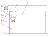
FIG. 1 is a schematic structural view of the present invention;
FIG. 2 is a schematic sectional view of the present invention;
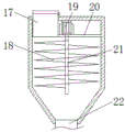
FIG. 3 is a schematic sectional view of the discharge hopper of the present invention;
fig. 4 is the structural schematic diagram of the supporting plate with a right-side view.
In the figure: 1. a base plate; 2. a food drinking groove; 3. a support bar; 4. climbing a ladder; 5. a discharge hopper; 6. a first rotating electric machine; 7. placing a box; 8. a support plate; 9. a connecting rod; 10. an electromagnetic valve; 11. a threaded sleeve; 12. a first slider; 13. a first chute; 14. a screw; 15. a through groove; 16. a second chute; 17. a feed pipe; 18. a crushing blade; 19. a second rotating electric machine; 20. a partition plate; 21. crushing the stems; 22. a discharging pipe; 23. and a second slider.
Detailed Description
The technical solutions in the embodiments of the present invention will be described clearly and completely with reference to the accompanying drawings in the embodiments of the present invention, and it is obvious that the described embodiments are only some embodiments of the present invention, not all embodiments. Based on the embodiments in the present invention, all other embodiments obtained by a person skilled in the art without creative work belong to the protection scope of the present invention.
In the description of the present invention, it should be noted that the terms "upper", "lower", "inner", "outer", "front end", "rear end", "both ends", "one end", "the other end", and the like indicate orientations or positional relationships based on the orientations or positional relationships shown in the drawings, and are only for convenience of description and simplification of description, but do not indicate or imply that the device or element to be referred must have a specific orientation, be constructed in a specific orientation, and be operated, and thus, should not be construed as limiting the present invention. Furthermore, the terms "first" and "second" are used for descriptive purposes only and are not to be construed as indicating or implying relative importance.
In the description of the present invention, it is to be noted that, unless otherwise explicitly specified or limited, the terms "mounted", "provided", "connected", and the like are to be construed broadly, such as "connected", which may be fixedly connected, detachably connected, or integrally connected; can be mechanically or electrically connected; they may be connected directly or indirectly through intervening media, or they may be interconnected between two elements. The specific meaning of the above terms in the present invention can be understood in specific cases to those skilled in the art.
The utility model discloses a bottom plate 1, diet groove 2, bracing piece 3, cat ladder 4, blowing fill 5, first rotation motor 6, place case 7, backup pad 8, connecting rod 9, solenoid valve 10, swivel nut 11, first slider 12, first spout 13, screw rod 14, lead to groove 15, second spout 16, inlet pipe 17, crushing blade 18, second rotation motor 19, baffle 20, crushing pole 21, unloading pipe 22 and second slider 23 part are the parts that universal standard spare or technical personnel in the field know, its structure and principle all are that this technical staff all can learn through the technical manual or learn through conventional experimental method.
Referring to fig. 1-4, an automatic feed adding device for livestock breeding comprises a bottom plate 1, a feeding trough 2 is fixedly connected to the top of the bottom plate 1, a ladder 4 is fixedly connected to the left side of the bottom plate 1, support rods 3 are fixedly connected to the periphery of the top of the bottom plate 1, two support plates 8 are fixedly connected to the inner sides of the support rods 3, a second chute 16 is formed in the inner side of each support plate 8, a second slider 23 is slidably connected to the inner cavity of the second chute 16, the inner side of each second slider 23 is fixedly connected to the outer side of a discharging hopper 5, the discharging hopper 5 is supported by the arrangement of the second chute 16 and the second slider 23, the stability and the smoothness of the discharging hopper 5 in the left-right moving process are effectively improved, a placing box 7 is fixedly connected to the top of each support rod 3, a first rotating motor 6 is fixedly connected to the left side of the placing box 7, the output end of the first rotating motor 6 is fixedly connected with a screw rod 14, the right side of the screw rod 14 is movably connected to the right side of the inner wall of the placing box 7 through a bearing, the surface of the screw rod 14 is in threaded connection with a threaded sleeve 11, the top of the inner wall of the placing box 7 is provided with a first sliding groove 13, the inner cavity of the first sliding groove 13 is in sliding connection with a first sliding block 12, the bottom of the first sliding block 12 is fixedly connected to the top of the threaded sleeve 11, through the arrangement of the first sliding groove 13 and the threaded sleeve 11, the stability and the smoothness in the left-right moving process of the threaded sleeve 11 are effectively improved, the bottom of the threaded sleeve 11 is fixedly connected with a connecting rod 9, the bottom of the placing box 7 is provided with a through groove 15, the connecting rod 9 penetrates to the bottom of the placing box 7 through the through groove 15, the bottom of the connecting rod 9 is fixedly connected with, the second rotates the crushing pole 21 of 19 output fixedly connected with of motor, and the fixed surface of crushing pole 21 is connected with and smashes blade 18, the output that rotates motor 19 through the second drives crushing pole 21 and rotates, crushing pole 21 drives and smashes blade 18 and rotates, smash the fodder, avoid the too big unloading pipe 22 that blocks up of fodder granule to lead to unable automatic feeding, the left side intercommunication at 5 tops of blowing fill has inlet pipe 17, and the bottom of inlet pipe 17 communicates to the bottom of baffle 20, the bottom intercommunication of blowing fill 5 has unloading pipe 22, the surface of unloading pipe 22 is provided with solenoid valve 10.
When the feed adding device is used, firstly, the cover plate is lifted to place feed into an inner cavity of the discharge hopper 5, when the feed is required to be added, the first rotating motor 6 is started through the external controller, the output end of the first rotating motor 6 drives the screw rod 14 to rotate, the screw rod 14 drives the screw sleeve 11 to move towards the right side through the action of the threads, the screw sleeve 11 drives the discharge hopper 5 to move towards the right side through the connecting rod 9, then the electromagnetic valve 10 is opened through the external controller, the feed falls into the inner cavity of the diet groove 2 through the discharge pipe 22, the purpose of automatically adding the feed is achieved, meanwhile, the second rotating motor 19 is started through the external controller, the output end of the second rotating motor 19 drives the crushing rod 21 to rotate, the crushing rod 21 drives the crushing blade 18 to rotate, the feed is crushed, the blockage of the discharge pipe 22 by overlarge feed particles is avoided (the external controller is a PLC controller in the application, and meanwhile, two wiring terminals of the external controller are connected with, and mains power is used for power supply in this application).
While embodiments of the present invention have been shown and described, it will be apparent to those skilled in the art that various modifications and changes can be made in the present invention. Any modification, equivalent replacement, improvement, etc. made within the spirit and principle of the present invention should be included in the scope of the claims of the present invention.
Claims (5)
1. The utility model provides a device is added with fodder is automatic to livestock-raising, includes bottom plate (1), its characterized in that: the supporting rods (3) are fixedly connected to the periphery of the top of the bottom plate (1), the top of each supporting rod (3) is fixedly connected with a placing box (7), the left side of each placing box (7) is fixedly connected with a first rotating motor (6), the output end of each first rotating motor (6) is fixedly connected with a screw rod (14), the right side of each screw rod (14) is movably connected to the right side of the inner wall of each placing box (7) through a bearing, the surface threads of each screw rod (14) are connected with a threaded sleeve (11), the bottom of each threaded sleeve (11) is fixedly connected with a connecting rod (9), the bottom of each placing box (7) is provided with a through groove (15), each connecting rod (9) penetrates through the bottom of each placing box (7) through the through groove (15), the bottom of each connecting rod (9) is fixedly connected with a discharging hopper (5), and the bottom of each discharging hopper (, the surface of the blanking pipe (22) is provided with an electromagnetic valve (10).
2. The automatic feed adding device for livestock breeding according to claim 1, characterized in that: the top fixedly connected with baffle (20) of blowing fill (5) inner chamber, the top fixedly connected with second of baffle (20) rotates motor (19), the second rotates the crushing pole (21) of output fixedly connected with of motor (19), and smashes surperficial fixedly connected with crushing blade (18) of pole (21), the left side intercommunication at blowing fill (5) top has inlet pipe (17), and the bottom of inlet pipe (17) communicates to the bottom of baffle (20).
3. The automatic feed adding device for livestock breeding according to claim 1, characterized in that: the utility model discloses a hopper, including bracing piece (3), inboard fixedly connected with backup pad (8) of bracing piece (3), and the quantity of backup pad (8) is two, second spout (16) have been seted up to the inboard of backup pad (8), the inner chamber sliding connection of second spout (16) has second slider (23), the inboard fixed connection of second slider (23) is in the outside of blowing fill (5).
4. The automatic feed adding device for livestock breeding according to claim 1, characterized in that: place the top of case (7) inner wall and seted up first spout (13), the inner chamber sliding connection of first spout (13) has first slider (12), and the bottom fixed connection of first slider (12) in the top of swivel nut (11).
5. The automatic feed adding device for livestock breeding according to claim 1, characterized in that: the top of the bottom plate (1) is fixedly connected with a food drinking groove (2), and the left side of the bottom plate (1) is fixedly connected with a ladder stand (4).
Priority Applications (1)
| Application Number | Priority Date | Filing Date | Title |
|---|---|---|---|
| CN202022236047.1U CN213639255U (en) | 2020-10-10 | 2020-10-10 | Automatic device that adds of fodder for livestock-raising |
Applications Claiming Priority (1)
| Application Number | Priority Date | Filing Date | Title |
|---|---|---|---|
| CN202022236047.1U CN213639255U (en) | 2020-10-10 | 2020-10-10 | Automatic device that adds of fodder for livestock-raising |
Publications (1)
| Publication Number | Publication Date |
|---|---|
| CN213639255U true CN213639255U (en) | 2021-07-09 |
Family
ID=76701773
Family Applications (1)
| Application Number | Title | Priority Date | Filing Date |
|---|---|---|---|
| CN202022236047.1U Expired - Fee Related CN213639255U (en) | 2020-10-10 | 2020-10-10 | Automatic device that adds of fodder for livestock-raising |
Country Status (1)
| Country | Link |
|---|---|
| CN (1) | CN213639255U (en) |
Cited By (1)
| Publication number | Priority date | Publication date | Assignee | Title |
|---|---|---|---|---|
| CN114275199A (en) * | 2022-01-08 | 2022-04-05 | 界首市祥云面粉有限公司 | Quantitative flour bagging device |
-
2020
- 2020-10-10 CN CN202022236047.1U patent/CN213639255U/en not_active Expired - Fee Related
Cited By (1)
| Publication number | Priority date | Publication date | Assignee | Title |
|---|---|---|---|---|
| CN114275199A (en) * | 2022-01-08 | 2022-04-05 | 界首市祥云面粉有限公司 | Quantitative flour bagging device |
Similar Documents
| Publication | Publication Date | Title |
|---|---|---|
| CN214233935U (en) | Feed particle forming machine | |
| CN109349152B (en) | Automatic feeding equipment for livestock breeding based on lever principle | |
| CN211246366U (en) | Efficient feed mixing device for livestock breeding | |
| CN109757392B (en) | A beef cattle feed feeding and supplying system and working method | |
| CN112056240B (en) | Breeding equipment for breeding industry | |
| CN213095476U (en) | Automatic feeding device of pig raising fodder | |
| CN212184655U (en) | Automatic feeding device for livestock breeding | |
| CN211298086U (en) | Poultry is bred and uses excrement and urine cleaning device | |
| CN211538074U (en) | Forage grass feed processing device capable of preventing spraying | |
| CN210183958U (en) | Livestock-raising is with forage reducing mechanism that can add water automatically | |
| CN208836796U (en) | A kind of chicken device for feeding that convenience is cleared up automatically | |
| CN219228705U (en) | Novel livestock-raising large-scale chicken feeding device | |
| CN214183253U (en) | Poultry is with fodder reducing mechanism | |
| CN207284674U (en) | A kind of liftable pig fodder groove | |
| CN213523411U (en) | A feeding device based on animal husbandry | |
| CN207911717U (en) | Feeding device for animal husbandry | |
| CN211205480U (en) | Weighing device for livestock breeding | |
| CN109661910A (en) | A kind of herding forage cutting pressure setting | |
| CN211020491U (en) | An automatic feeding device for feeding troughs for animal husbandry | |
| CN211134060U (en) | Be used for farm to breed fodder crushing equipment | |
| CN209983293U (en) | Novel feed mixing equipment for livestock-raising | |
| CN211322498U (en) | Beef cattle breeding automatic material conveying device | |
| CN213281058U (en) | Feeder is fattened in child care convenient to use | |
| CN217038443U (en) | Local chicken is bred and throws feeding device with fodder with memory function | |
| CN212545494U (en) | Livestock-raising feed processing device |
Legal Events
| Date | Code | Title | Description |
|---|---|---|---|
| GR01 | Patent grant | ||
| GR01 | Patent grant | ||
| CF01 | Termination of patent right due to non-payment of annual fee |
Granted publication date: 20210709 |
|
| CF01 | Termination of patent right due to non-payment of annual fee |