CN213636836U - A low-voltage complete set of fixed switch cabinet - Google Patents

A low-voltage complete set of fixed switch cabinet Download PDF

Info

Publication number
CN213636836U
CN213636836U CN202022668988.2U CN202022668988U CN213636836U CN 213636836 U CN213636836 U CN 213636836U CN 202022668988 U CN202022668988 U CN 202022668988U CN 213636836 U CN213636836 U CN 213636836U
Authority
CN
China
Prior art keywords
fixed
pipe
box
heat dissipation
low
Prior art date
Legal status (The legal status is an assumption and is not a legal conclusion. Google has not performed a legal analysis and makes no representation as to the accuracy of the status listed.)
Expired - Fee Related
Application number
CN202022668988.2U
Other languages
Chinese (zh)
Inventor
陶汝建
Current Assignee (The listed assignees may be inaccurate. Google has not performed a legal analysis and makes no representation or warranty as to the accuracy of the list.)
Inner Mongolia Oumeng Power Equipment Manufacturing Installation Co ltd
Original Assignee
Kunming Zhenbiao Electrical Equipment Co ltd
Priority date (The priority date is an assumption and is not a legal conclusion. Google has not performed a legal analysis and makes no representation as to the accuracy of the date listed.)
Filing date
Publication date
Application filed by Kunming Zhenbiao Electrical Equipment Co ltd filed Critical Kunming Zhenbiao Electrical Equipment Co ltd
Priority to CN202022668988.2U priority Critical patent/CN213636836U/en
Application granted granted Critical
Publication of CN213636836U publication Critical patent/CN213636836U/en
Expired - Fee Related legal-status Critical Current
Anticipated expiration legal-status Critical

Links

Images

Landscapes

  • Patch Boards (AREA)

Abstract

本实用新型公开了一种低压成套固定式开关柜,包括箱体,散热板上安装有电器元件,散热板的内部开设有散热管,水泵的输出端连接有进水管,进水管的另一端与散热管的进水端相连通,散热管的出水端与出水管相连通,出水管的另一端与储水箱相连接,旋转电机的输出端连接有螺纹杆,螺纹杆上螺纹安装有滑座,滑座的侧端固定有套筒,套筒的内部安装有伸缩弹簧,伸缩弹簧的一端固定有伸缩杆,伸缩杆的另一端固定有安装板,安装板上安装有毛刷,箱体的侧端开设有若干个进气孔,箱体的上端安装有出气管,出气管内通过固定杆固定安装有排风扇,出气管的上端连通有通风管。本实用新型不仅散热方式多样,散热效果好,而除尘效果好。
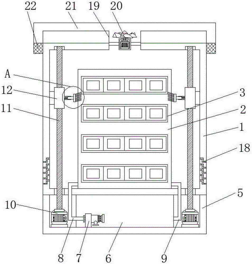
Figure 202022668988

The utility model discloses a low-voltage complete set of fixed switch cabinet, comprising a box body, electrical components are mounted on a heat dissipation plate, a heat dissipation pipe is arranged inside the heat dissipation plate, an output end of a water pump is connected with a water inlet pipe, and the other end of the water inlet pipe is connected with The water inlet end of the heat dissipation pipe is connected, the water outlet end of the heat dissipation pipe is connected with the water outlet pipe, the other end of the water outlet pipe is connected with the water storage tank, the output end of the rotating motor is connected with a threaded rod, and the threaded rod is threaded with a sliding seat. The side end of the sliding seat is fixed with a sleeve, a telescopic spring is installed inside the sleeve, one end of the telescopic spring is fixed with a telescopic rod, the other end of the telescopic rod is fixed with a mounting plate, and a brush is installed on the mounting plate. The end is provided with a number of air intake holes, the upper end of the box body is provided with an air outlet pipe, an exhaust fan is fixedly installed in the air outlet pipe through a fixing rod, and a ventilation pipe is communicated with the upper end of the air outlet pipe. The utility model not only has various heat dissipation modes, but also has good heat dissipation effect and good dust removal effect.

Figure 202022668988

Description

Low-voltage complete fixed switch cabinet
Technical Field
The utility model relates to a cubical switchboard technical field, in particular to fixed cubical switchboard of low pressure complete set.
Background
The switch cabinet is an electrical device, the external line of the switch cabinet firstly enters a main control switch in the cabinet and then enters a branch control switch, and each branch is arranged according to the requirement. Such as meters, automatic controls, magnetic switches of motors, various alternating current contactors, and the like, some of which are also provided with high-voltage chambers and low-voltage chamber switch cabinets, and high-voltage buses, such as power plants, and some of which are also provided with low-frequency load shedding for keeping main equipment. The switch cabinet can be divided into a high-voltage switch cabinet, a medium-voltage switch cabinet, a low-voltage switch cabinet and the like according to different voltage grades. The low-voltage complete fixed switch equipment is suitable for power users of power plants, substations, industrial and mining enterprises and the like to be used as power in a power distribution system with the alternating current of 50Hz, the rated working voltage of 380V and the rated current of 3150A, and is used for power conversion, distribution and control of lighting and power distribution equipment, the product has high breaking capacity, and the rated short-time withstand current reaches 50 KA.
The low-voltage complete fixed switch cabinet generates a large amount of heat in work, so that the internal temperature is high, the heat cannot be dissipated, and the service life of the low-voltage complete fixed switch cabinet is influenced; in addition, in the using process, external dust easily enters the interior of the low-voltage complete fixed switch cabinet, and the dust is accumulated on electrical elements, so that the electrical elements are easily damaged, and the normal operation of the low-voltage complete fixed switch cabinet is influenced.
SUMMERY OF THE UTILITY MODEL
The utility model discloses a main aim at provides a fixed cubical switchboard of low pressure complete set can effectively solve the problem in the background art.
In order to achieve the above purpose, the utility model adopts the following technical scheme:
a low-voltage complete set fixed switch cabinet comprises a cabinet body, wherein a heat dissipation plate is arranged inside the cabinet body, an electrical element is arranged on the heat dissipation plate, a heat dissipation pipe is arranged inside the heat dissipation plate, a base is fixed at the lower end of the cabinet body, a water storage tank is arranged inside the base, a water pump is arranged inside the water storage tank, the output end of the water pump is connected with a water inlet pipe, the other end of the water inlet pipe is communicated with the water inlet end of the heat dissipation pipe, the water outlet end of the heat dissipation pipe is communicated with a water outlet pipe, the other end of the water outlet pipe is connected with the water storage tank, a rotating motor is arranged inside the base, the output end of the rotating motor is connected with a threaded rod, the upper end of the threaded rod penetrates through the cabinet body and extends into, the side of slide is fixed with the sleeve, telescopic internally mounted has expanding spring, expanding spring's one end is fixed with the telescopic link, the other end of telescopic link is fixed with the mounting panel, install the brush on the mounting panel, just a plurality of inlet port has been seted up to the side of box, the outlet duct is installed to the upper end of box, there is the exhaust fan through dead lever fixed mounting in the outlet duct, just the upper end intercommunication of outlet duct has the ventilation pipe, the mouth of pipe department of ventilation pipe installs the dust removal net.
Preferably, the air inlet hole is of a Z-shaped structure, and a filter screen is arranged inside the air inlet hole.
Preferably, the rotating motor, the threaded rod, the sliding seat, the sleeve, the telescopic spring, the telescopic rod, the mounting plate and the hairbrush are all provided with two groups.
Preferably, the ventilation pipe is of an L-shaped structure, and the pipe orifice of the ventilation pipe faces downwards.
Preferably, the telescopic rod is connected with the inner wall of the sleeve in a sliding mode through a sliding block.
Preferably, the front end of the box body is movably provided with a box door through a hinge.
Compared with the prior art, the utility model discloses following beneficial effect has: the low-voltage complete fixed switch cabinet is characterized in that when the low-voltage complete fixed switch cabinet is used, an electrical component generates heat when working, the heat is transferred to the heat dissipation plate and the interior of a box body, a water pump is started, the water pump conveys distilled water in a water storage tank into the heat dissipation plate through a water inlet pipe, the distilled water in the heat dissipation plate exchanges heat with the heat dissipation plate, the temperature of the heat dissipation plate is reduced, the temperature of the electrical component is conveniently reduced and the heat is dissipated, the distilled water in the heat dissipation plate enters the water storage tank from a water outlet pipe to be circulated, an exhaust fan is started simultaneously, external air enters the interior of the box body from an air inlet hole, the air in the box body is conveyed to a ventilation pipe from an air outlet pipe to be discharged outside from, reciprocating motion about the positive and negative reciprocating rotation of threaded rod drives the slide to reciprocating motion about driving the brush, the dust on the brush clearance electrical components of being convenient for, brush extrusion electrical components, the flexible position of being convenient for adjust the brush of expanding spring, the dust on the brush clearance electrical components of being convenient for, the cleaning performance is good, the dust of clearance is discharged by the exhaust fan along with the air in the box, and the dust removal net is collected the dust, prevents the dust polluted air.
Drawings
Fig. 1 is a schematic view of the overall structure of a low-voltage complete fixed switch cabinet of the present invention;
fig. 2 is a schematic plan view of a heat dissipation plate of a low-voltage complete fixed switch cabinet according to the present invention;
fig. 3 is an enlarged schematic structural diagram of a portion a in fig. 1 of a low-voltage complete fixed switchgear of the present invention.
In the figure: 1. a box body; 2. a heat dissipation plate; 3. an electrical component; 4. a radiating pipe; 5. a base; 6. a water storage tank; 7. a water pump; 8. a water inlet pipe; 9. a water outlet pipe; 10. a rotating electric machine; 11. a threaded rod; 12. a slide base; 13. a sleeve; 14. a tension spring; 15. a telescopic rod; 16. mounting a plate; 17. a brush; 18. an air inlet; 19. an air outlet pipe; 20. an exhaust fan; 21. a vent pipe; 22. a dust removal net.
Detailed Description
In order to make the technical means, creation features, achievement purposes and functions of the present invention easy to understand, the present invention is further described below with reference to the following embodiments.
As shown in fig. 1-3, a low-voltage complete fixed switch cabinet comprises a cabinet 1, a heat dissipation plate 2 is installed inside the cabinet 1, an electrical component 3 is installed on the heat dissipation plate 2, a heat dissipation tube 4 is installed inside the heat dissipation plate 2, a base 5 is fixed at the lower end of the cabinet 1, a water storage tank 6 is installed inside the base 5, a water pump 7 is installed inside the water storage tank 6, an output end of the water pump 7 is connected with a water inlet tube 8, the other end of the water inlet tube 8 is communicated with a water inlet end of the heat dissipation tube 4, a water outlet end of the heat dissipation tube 4 is communicated with a water outlet tube 9, the other end of the water outlet tube 9 is connected with the water storage tank 6, a rotating motor 10 is installed inside the base 5, an output end of the rotating motor 10 is connected with a threaded rod 11, an, threaded mounting has slide 12 on threaded rod 11, slide 12's one end passes through the inside sliding connection of slider and box 1, slide 12's side is fixed with sleeve 13, sleeve 13's internally mounted has expanding spring 14, expanding spring 14's one end is fixed with telescopic link 15, telescopic link 15's the other end is fixed with mounting panel 16, install brush 17 on the mounting panel 16, just a plurality of inlet port 18 has been seted up to box 1's side, outlet duct 19 is installed to box 1's upper end, there is exhaust fan 20 through dead lever fixed mounting in the outlet duct 19, just the upper end intercommunication of outlet duct 19 has ventilation pipe 21, dust removal net 22 is installed to the mouth of pipe department of ventilation pipe 21.
In this embodiment, preferably, the air inlet 18 is a Z-shaped structure, and a filter screen is installed inside the air inlet 18 to prevent dust from entering the inside of the box body 1 through the air inlet 18.
In this embodiment, preferably, two sets of the rotating motor 10, the threaded rod 11, the sliding seat 12, the sleeve 13, the extension spring 14, the extension rod 15, the mounting plate 16 and the brush 17 are provided, so as to clean dust on the electrical component 3.
In this embodiment, preferably, the ventilation pipe 21 is in an L-shaped structure, and a nozzle of the ventilation pipe 21 faces downward, so as to prevent dust from entering the inside of the box body 1 from the ventilation pipe 21.
In this embodiment, preferably, the telescopic rod 15 is slidably connected to the inner wall of the sleeve 13 through a sliding block, so that the telescopic rod 15 can move in the sleeve 13 conveniently.
In this embodiment, preferably, a box door is movably mounted at the front end of the box body 1 through a hinge, so that the box door can be opened to inspect and maintain the electrical component 3 inside the box body 1.
It should be noted that, the utility model relates to a fixed cubical switchboard of low pressure complete set, in use, electrical components 3 produce heat during operation, the heat transmits to the inside of heating panel 2 and box 1, start water pump 7, water pump 7 transports the distilled water in storage water tank 6 to in the cooling tube 4 through inlet tube 8, the distilled water in the cooling tube 4 exchanges heat with heating panel 2, the temperature of heating panel 2 reduces, thereby the temperature of electrical components 3 reduces, be convenient for the cooling and heat dissipation of electrical components 3, the distilled water in the cooling tube 4 enters into storage water tank 6 from outlet tube 9 and circulates, start exhaust fan 20 simultaneously, external air enters into the inside of box 1 from inlet port 18, exhaust fan 20 transports the air in box 1 to ventilation pipe 21 from outlet duct 19, discharge from the outside from ventilation pipe 21, be convenient for the circulation of the air in box 1, be convenient for heat dissipation, the radiating effect is good, start rotating electrical machines 10, rotating electrical machines 10 is just reciprocal rotatory, rotating electrical machines 10 is rotatory to be driven 11 positive and negative reciprocal rotations of threaded rod, 11 positive and negative reciprocal rotations of threaded rod drive slide 12 up-and-down reciprocating motion, thereby drive brush 17 up-and-down reciprocating motion, be convenient for brush 17 clearance dust on the electrical components 3, brush 17 extrusion electrical components 3, the flexible position of being convenient for adjust brush 17 of expanding spring 14, be convenient for brush 17 clearance dust on the electrical components 3, the cleaning performance is good, the dust of clearance is discharged by exhaust fan 20 along with the air in the box 1, dust removal net 22 is collected the dust, prevent dust polluted air.
The basic principles and the main features of the invention and the advantages of the invention have been shown and described above. It will be understood by those skilled in the art that the present invention is not limited to the above embodiments, and that the foregoing embodiments and descriptions are provided only to illustrate the principles of the present invention without departing from the spirit and scope of the present invention. The scope of the invention is defined by the appended claims and equivalents thereof.

Claims (6)

1. The utility model provides a fixed cubical switchboard of low pressure complete set, includes box (1), its characterized in that: the internal mounting of box (1) has heating panel (2), install electrical components (3) on heating panel (2), just cooling tube (4) have been seted up to the inside of heating panel (2), the lower extreme of box (1) is fixed with base (5), the internal mounting of base (5) has storage water tank (6), the internal mounting of storage water tank (6) has water pump (7), the output of water pump (7) is connected with inlet tube (8), the other end of inlet tube (8) is linked together with the intake end of cooling tube (4), the play water end of cooling tube (4) is linked together with outlet pipe (9), the other end of outlet pipe (9) is connected with storage water tank (6), and the internal mounting of base (5) has rotating electrical machines (10), the output of rotating electrical machines (10) is connected with threaded rod (11), the upper end of threaded rod (11) runs through the inside that box (1) extended to box (1), threaded rod (11) is gone up the screw thread and is installed slide (12), the inside sliding connection of slider and box (1) is passed through to the one end of slide (12), the side of slide (12) is fixed with sleeve (13), the internally mounted of sleeve (13) has expanding spring (14), the one end of expanding spring (14) is fixed with telescopic link (15), the other end of telescopic link (15) is fixed with mounting panel (16), install brush (17) on mounting panel (16), just a plurality of inlet port (18) have been seted up to the side of box (1), outlet duct (19) are installed to the upper end of box (1), through dead lever fixed mounting have exhaust fan (20) in outlet duct (19), just the upper end intercommunication of outlet duct (19) has ventilation pipe (21), and a dust removal net (22) is arranged at the pipe orifice of the ventilation pipe (21).
2. A low-voltage fixed switchgear panel as claimed in claim 1, characterized in that: the air inlet hole (18) is of a Z-shaped structure, and a filter screen is arranged inside the air inlet hole (18).
3. A low-voltage fixed switchgear panel as claimed in claim 1, characterized in that: the rotary electric machine (10), the threaded rod (11), the sliding seat (12), the sleeve (13), the telescopic spring (14), the telescopic rod (15), the mounting plate (16) and the hairbrush (17) are all provided with two groups.
4. A low-voltage fixed switchgear panel as claimed in claim 1, characterized in that: the ventilation pipe (21) is of an L-shaped structure, and the opening of the ventilation pipe (21) faces downwards.
5. A low-voltage fixed switchgear panel as claimed in claim 1, characterized in that: the telescopic rod (15) is connected with the inner wall of the sleeve (13) in a sliding mode through the sliding block.
6. A low-voltage fixed switchgear panel as claimed in claim 1, characterized in that: the front end of the box body (1) is movably provided with a box door through a hinge.
CN202022668988.2U 2020-11-18 2020-11-18 A low-voltage complete set of fixed switch cabinet Expired - Fee Related CN213636836U (en)

Priority Applications (1)

Application Number Priority Date Filing Date Title
CN202022668988.2U CN213636836U (en) 2020-11-18 2020-11-18 A low-voltage complete set of fixed switch cabinet

Applications Claiming Priority (1)

Application Number Priority Date Filing Date Title
CN202022668988.2U CN213636836U (en) 2020-11-18 2020-11-18 A low-voltage complete set of fixed switch cabinet

Publications (1)

Publication Number Publication Date
CN213636836U true CN213636836U (en) 2021-07-06

Family

ID=76634265

Family Applications (1)

Application Number Title Priority Date Filing Date
CN202022668988.2U Expired - Fee Related CN213636836U (en) 2020-11-18 2020-11-18 A low-voltage complete set of fixed switch cabinet

Country Status (1)

Country Link
CN (1) CN213636836U (en)

Cited By (5)

* Cited by examiner, † Cited by third party
Publication number Priority date Publication date Assignee Title
CN114243480A (en) * 2021-12-29 2022-03-25 南京达尔威机电设备有限公司 Heat dissipation system for distribution box
CN117096757A (en) * 2023-07-24 2023-11-21 浙江旭锐电气有限公司 An anti-interference and reliable switch cabinet
CN117424111A (en) * 2023-11-29 2024-01-19 安徽德睿智能技术有限公司 Intelligent protection device of preassembled high-voltage power distribution cabinet
CN117415067A (en) * 2023-10-23 2024-01-19 安徽能通新能源科技有限公司 An energy storage device that can automatically clean cooling air vents
CN118174163A (en) * 2024-04-24 2024-06-11 山东济电德能电气集团有限公司 A dust removal device for outdoor complete switchgear

Cited By (5)

* Cited by examiner, † Cited by third party
Publication number Priority date Publication date Assignee Title
CN114243480A (en) * 2021-12-29 2022-03-25 南京达尔威机电设备有限公司 Heat dissipation system for distribution box
CN117096757A (en) * 2023-07-24 2023-11-21 浙江旭锐电气有限公司 An anti-interference and reliable switch cabinet
CN117415067A (en) * 2023-10-23 2024-01-19 安徽能通新能源科技有限公司 An energy storage device that can automatically clean cooling air vents
CN117424111A (en) * 2023-11-29 2024-01-19 安徽德睿智能技术有限公司 Intelligent protection device of preassembled high-voltage power distribution cabinet
CN118174163A (en) * 2024-04-24 2024-06-11 山东济电德能电气集团有限公司 A dust removal device for outdoor complete switchgear

Similar Documents

Publication Publication Date Title
CN214227559U (en) Heat dissipation structure of power distribution equipment
CN213989682U (en) Cleaning equipment for high-low voltage power distribution cabinet
CN220209644U (en) Low-voltage switching device
CN215955771U (en) Dustproof high-low voltage distribution cabinet ventilates
CN216048350U (en) High-efficient air can heat pump device
CN211151095U (en) Fixed high tension switchgear
CN213847258U (en) Electrical control box for engineering machinery
CN213782686U (en) Alternating-current low-voltage power distribution cabinet with heat dissipation structure
CN210502687U (en) Subway air conditioner of adjustable amount of wind filters return air duct
CN218732655U (en) Switch cabinet structure
CN216436596U (en) Distribution room is with high-low voltage switch cabinet convenient to overhaul
CN210041335U (en) Dust-protection type intelligence condenser
CN211183066U (en) Low-voltage switch cabinet
CN211629694U (en) Cubical switchboard that heat dispersion is good
CN214958062U (en) High-integration low-voltage draw-out type switch cabinet
CN216903944U (en) New energy automobile fills high voltage distribution box for electric pile
CN220138967U (en) High-low voltage switch cabinet convenient to clean
CN220382968U (en) Medium-voltage alternating-current frequency converter
CN220652633U (en) Reliable fixed metal-enclosed ring main unit
CN217656229U (en) Switch cabinet with air purification device
CN219498551U (en) Prevent wind husky switch board
CN213989805U (en) Low-voltage control cabinet
CN219980106U (en) Dustproof high-voltage power distribution cabinet
CN222735638U (en) A heat dissipation type power distribution cabinet
CN220107230U (en) Dust type switch board

Legal Events

Date Code Title Description
GR01 Patent grant
GR01 Patent grant
TR01 Transfer of patent right

Effective date of registration: 20240909

Address after: No. 5 Qingyuan Road, Equipment Manufacturing Industrial Park, Qingshan District, Baotou City, Inner Mongolia Autonomous Region, 014000

Patentee after: INNER MONGOLIA OUMENG POWER EQUIPMENT MANUFACTURING INSTALLATION Co.,Ltd.

Country or region after: China

Address before: No.4, building 21, phase II, Tuqiao hardware, electromechanical and building materials City, Kunming Dengding market, no.1585, Yulong Road, Guandu District, Kunming, Yunnan, 650200

Patentee before: Kunming zhenbiao Electrical Equipment Co.,Ltd.

Country or region before: China

TR01 Transfer of patent right
CF01 Termination of patent right due to non-payment of annual fee

Granted publication date: 20210706

CF01 Termination of patent right due to non-payment of annual fee