Independent support die carrier
Technical Field
The utility model relates to a building engineering technical field, concretely relates to independent support die carrier.
Background
The building formwork is a temporary supporting structure, which is manufactured according to the design requirements, so that the concrete structure and the members are formed according to the specified positions and geometric dimensions, the correct positions of the concrete structure and the members are kept, and the self weight of the building formwork and the external load acting on the building formwork are borne. The existing formwork support system mostly adopts a mode of combining a rod type steel pipe with a fastener, and the formwork support system has the following two problems:
on one hand, when the structures such as a main beam, a secondary beam and the like of a floor slab are supported, the vertical rods cannot be transversely connected with other vertical rods, the cross rods can be connected between the vertical rods only in a traditional steel pipe fastener mode, and then battens for supporting templates are placed on the cross rods. The mode wastes manpower and material resources and has larger potential safety hazard.
On the other hand, some supporting die systems are connected with adjustable screw rods and jacking plates in the vertical rods in a sleeved mode, the top plates are used for placing formboard battens, nuts and sleeves of the adjustable screw rods are only connected in a pipe surface contact mode, so that the freedom degree of the contact surfaces of the sleeves and the nuts is large, the battens on the sleeves and the hasps can be caused to displace under a certain transverse stress condition, and even the stability of the jacking plates and the top plates of the screw rods is influenced.
SUMMERY OF THE UTILITY MODEL
The utility model provides a not enough to prior art, the utility model provides an independent support die carrier can replace the steel pipe bridging structure of traditional mode through utilizing two die carriers, utilizes the floorbar to connect the back can be to template direct mount on the secondary beam, has not only practiced thrift the quantity of steel pipe, makes the activity space increase between two die carriers moreover, conveniently dismantles and tear the quick detach early, and can have enough to meet the need the use many times, reduces the shakeout expense.
The utility model discloses a realize through following technical scheme:
the independent supporting die frame comprises a lifting cylinder and a supporting cylinder, wherein the lifting cylinder is fixedly provided with a bottom plate which is used for being connected with a lifting mechanism; the lower part of the supporting cylinder is fixedly connected with the upper part of the lifting cylinder through bolts and nuts, the upper end of the supporting cylinder is fixedly connected with a supporting plate, and a connecting piece used for connecting a bottom beam is fixed on the supporting plate.
The support cylinder between the two die carriers is connected through the connecting piece and the bottom beam to form the whole die carrier, the structure of a steel pipe building frame in the traditional mode is replaced, construction can be carried out between each floor of a building through the two die carriers, the die carriers can be lowered by the lifting mechanism to be hoisted from the lower layer to the upper layer to be continuously used, and recycling can be achieved.
Furthermore, the connecting piece comprises two vertical plates welded and fixed on the supporting plate, and the two vertical plates are provided with connecting holes at the same positions.
The connecting holes between the vertical plates are connected with the bottom beam and are used for connecting the two die carriers to form an integrated structure.
Furthermore, lifting lugs are welded and fixed on the outer walls of the lifting cylinder and the supporting cylinder.
In order to guarantee the stability of support, the quality of a lift section of thick bamboo and a support section of thick bamboo is great, needs to hoist and mount the installation, and the lug can be connected the bracing between the stationary plane in addition, improves stability.
As an embodiment of the utility model, elevating system establishes outside the lift section of thick bamboo and with a lift section of thick bamboo sliding connection's a fixed section of thick bamboo including the cover, installs the self-locking type electric jack who connects the power cord in the fixed section of thick bamboo, offsets from the piston rod and the bottom plate of locking type electric jack.
The self-locking electric jack can be manually controlled to operate, and the lifting of the lifting cylinder is controlled by the expansion and contraction of the piston rod. The fixed cylinder is used for playing a supporting role when the lifting cylinder is lifted, so that the stability is improved, and the swinging can be effectively prevented.
Furthermore, the bottom surface of the fixed cylinder is sleeved with and fixed with an annular fixed plate, and the annular fixed plate is provided with at least two threaded holes and is connected with a mounting seat for fixed mounting through bolts and nuts.
The annular fixing plate is connected with the mounting seat through the bolts and the nuts, the mounting seat is separated from the fixing cylinder, the jack is convenient to maintain, the through hole is formed in the mounting seat, and the bolts can be fixedly connected with the fixing surface, so that the stability is improved.
Preferably, the outer wall of the lifting cylinder is provided with a sliding block, and the inner wall of the fixed cylinder is provided with a sliding way matched with the sliding block.
The lifting cylinder and the fixed cylinder are connected in a matched mode through the sliding block and the sliding way, so that when the lifting cylinder is lifted, the fixed cylinder can play a role in guiding the lifting cylinder, and the running stability is improved.
Furthermore, a lifting lug is welded and fixed on the fixed cylinder.
Besides being convenient for hoisting, the lifting lugs on the fixed cylinder can also be connected with the inclined struts after being static, so that the integral stability of the die carrier is enhanced.
As a second embodiment of the present invention, the lifting mechanism includes a lifting seat and at least two vertical screws fixed on the lifting seat, through holes for the screws to run through are respectively provided on the bottom plate, and an adjusting nut is screwed on each screw on the bottom plate.
When the weight of the die carrier is light and small, the overall height of the lifting cylinder and the supporting cylinder can be adjusted by utilizing the screw rod and nut structures, and the die carrier is fixed by utilizing the adjusting nut after the adjustment is finished.
The utility model has the advantages that:
compare traditional template support system, the die carrier of this scheme has sufficient intensity, rigidity and stability, guarantees construction smoothly and safety, installs and removes convenience, stable performance, safe and reliable, can have enough to meet the need the use many times, reduces the expense of amortizing. The utility model discloses reach the initial set back after the building is pour and is accomplished, alright will descend through elevating system and demolish, realize early tearing open the quick detach.
Drawings
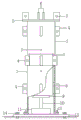
Fig. 1 is a schematic structural diagram of embodiment 1 of the present invention;
fig. 2 is a schematic structural diagram of embodiment 2 of the present invention.
Shown in the figure:
1. the lifting device comprises a lifting cylinder, 2, a supporting cylinder, 3, a bolt and nut, 4, a lifting lug, 5, a supporting plate, 6, a connecting piece, 7, a connecting hole, 8, a sliding block, 9, a supporting plate, 10, a piston rod, 11, a self-locking electric jack, 12, an annular fixing plate, 13, a mounting seat, 14, a bolt, 15, a screw rod, 16, an adjusting nut, 17, a bottom plate, 18 and a lifting seat.
Detailed Description
In order to clearly illustrate the technical features of the present solution, the present solution is explained below by way of specific embodiments.
Example 1:
as shown in fig. 1, an independent supporting die carrier comprises a lifting cylinder 1 and a supporting cylinder 2, wherein a bottom plate 17 used for being connected with a lifting mechanism is fixed on the lifting cylinder 1; the lower end of the supporting cylinder 2 is sleeved on the upper portion of the lifting cylinder 1 and fixedly connected with the lifting cylinder through a bolt and a nut 3, the upper end of the supporting cylinder 2 is fixedly connected with a supporting plate 5, and a connecting piece 6 used for connecting a bottom beam is fixed on the supporting plate 5. Of course, the supporting cylinder and the lifting cylinder 1 can be connected in other ways, such as flange connection.
The connecting piece 6 comprises two vertical plates welded and fixed on the supporting plate 5, and the two vertical plates are provided with connecting holes 7 at the same positions. Through the vertical plate arranged on the supporting plate 5, the two die carriers can be connected through the bottom beam to form an integral structure for bearing. In order to facilitate connection, four connecting pieces are arranged on the supporting plate, every two connecting pieces are in a group, and the connecting lines between the vertical plates of the two groups of connecting pieces are mutually vertical.
Lifting lugs 4 are welded and fixed on the outer walls of the lifting cylinder 1 and the supporting cylinder 2. The lifting lugs 4 can be applied during lifting, and can also be connected with inclined struts through holes of the lifting lugs to assist the whole stability of the die carrier. The lifting mechanism is a self-locking electric jack 11 connected with a power line, and a piston rod 10 of the self-locking electric jack 11 is abutted against the bottom plate. The lifting device further comprises a fixed cylinder 7 which is sleeved outside the lifting cylinder 1 and is in sliding connection with the lifting cylinder 1, and the jack 11 is installed in the fixed cylinder 7.
An annular fixing plate 12 is fixedly sleeved on the bottom surface of the fixing barrel 7, at least two threaded holes are formed in the annular fixing plate 12, and a mounting seat 13 for fixed mounting is connected to the annular fixing plate through a bolt and a nut 3. The fixed cylinder is connected with the mounting seat 13 through the bolts between the annular fixing plate 12 and the mounting seat 13, and when the jack is required to be overhauled, the fixed cylinder 7 is separated from the mounting seat 13 through the bolts, so that the jack is convenient to overhaul.
The outer wall of the lifting cylinder 1 is provided with a slide block 8, and the inner wall of the fixed cylinder 7 is provided with a slide way matched with the slide block 8. The fixed cylinder 7 is fixedly welded with a lifting lug 4, and similarly, the lifting lug 4 can also be connected with an inclined strut.
The utility model discloses a construction method:
the stability is improved by fixing the annular fixing plate 12 on the bottom surface of the fixing cylinder 7 with the mounting seat 13, and then fixing the mounting seat 13 with the ground through the bolt 14. A piston rod 10 of a self-locking electric jack 11 abuts against a bottom plate in a lifting cylinder 1, in order to reduce pressure intensity, a supporting plate 9 can be fixed at the end of the piston rod 10 to increase the stress area between the piston rod 10 and the bottom plate, the jack 11 is started to the maximum stroke, after the lifting cylinder 1 and a supporting cylinder 2 rise for 50cm generally, the self-locking jack 11 keeps the lifting cylinder 1 and the supporting cylinder 2 stable through self-locking continuous force application, and after initial setting is achieved after building pouring is completed, the lifting mechanism can descend to be disassembled, so that early disassembly and quick disassembly are realized.
Example 2:
compared with the embodiment 1, the independent supporting die carrier of the embodiment has smaller mass and volume, so that the lifting mechanism can be manually operated, the lifting mechanism comprises a lifting seat 18 and a self-locking electric jack 11 installed on the lifting seat 18, the lifting seat 18 is vertically fixed with at least two lead screws 15, as shown in fig. 2, 3 lead screws are arranged in total, the three lead screws are positioned on the same circumference, through holes for the lead screws 15 to penetrate through are respectively formed in the bottom plate 17, and the upper part and the lower part of the bottom plate 17 on each lead screw 15 are in threaded connection with an adjusting nut 16.
When the height of the lifting cylinder 1 is initially adjusted, the adjusting nut 16 above the bottom plate 17 is unscrewed, the lifting cylinder 1 and the supporting cylinder 2 can be integrally moved upwards by using a piston rod of the jack, after the position is determined, the adjusting nut 16 below the bottom plate 14 is screwed to the lower surface of the bottom plate 17, the adjusting nut above the bottom plate is adjusted to the upper surface of the bottom plate, and the position locking of the lifting cylinder 1 is realized by matching the self-locking function of the jack.
Of course, the above description is not limited to the above examples, and technical features of the present invention that are not described in the present application may be implemented by or using the prior art, and are not described herein again; the above embodiments and drawings are only used for illustrating the technical solutions of the present invention and are not intended to limit the present invention, and the present invention has been described in detail with reference to the preferred embodiments, and those skilled in the art should understand that changes, modifications, additions or substitutions made by those skilled in the art within the spirit of the present invention should also belong to the protection scope of the claims of the present invention.