CN213609085U - Patient interface - Google Patents
Patient interface Download PDFInfo
- Publication number
- CN213609085U CN213609085U CN201921742651.2U CN201921742651U CN213609085U CN 213609085 U CN213609085 U CN 213609085U CN 201921742651 U CN201921742651 U CN 201921742651U CN 213609085 U CN213609085 U CN 213609085U
- Authority
- CN
- China
- Prior art keywords
- patient
- fabric
- seal
- patient interface
- support structure
- Prior art date
- Legal status (The legal status is an assumption and is not a legal conclusion. Google has not performed a legal analysis and makes no representation as to the accuracy of the status listed.)
- Active
Links
Images


Classifications
-
- A—HUMAN NECESSITIES
- A61—MEDICAL OR VETERINARY SCIENCE; HYGIENE
- A61M—DEVICES FOR INTRODUCING MEDIA INTO, OR ONTO, THE BODY; DEVICES FOR TRANSDUCING BODY MEDIA OR FOR TAKING MEDIA FROM THE BODY; DEVICES FOR PRODUCING OR ENDING SLEEP OR STUPOR
- A61M16/00—Devices for influencing the respiratory system of patients by gas treatment, e.g. mouth-to-mouth respiration; Tracheal tubes
- A61M16/06—Respiratory or anaesthetic masks
- A61M16/0666—Nasal cannulas or tubing
-
- A—HUMAN NECESSITIES
- A61—MEDICAL OR VETERINARY SCIENCE; HYGIENE
- A61M—DEVICES FOR INTRODUCING MEDIA INTO, OR ONTO, THE BODY; DEVICES FOR TRANSDUCING BODY MEDIA OR FOR TAKING MEDIA FROM THE BODY; DEVICES FOR PRODUCING OR ENDING SLEEP OR STUPOR
- A61M16/00—Devices for influencing the respiratory system of patients by gas treatment, e.g. mouth-to-mouth respiration; Tracheal tubes
- A61M16/06—Respiratory or anaesthetic masks
- A61M16/0605—Means for improving the adaptation of the mask to the patient
- A61M16/0616—Means for improving the adaptation of the mask to the patient with face sealing means comprising a flap or membrane projecting inwards, such that sealing increases with increasing inhalation gas pressure
-
- A—HUMAN NECESSITIES
- A61—MEDICAL OR VETERINARY SCIENCE; HYGIENE
- A61M—DEVICES FOR INTRODUCING MEDIA INTO, OR ONTO, THE BODY; DEVICES FOR TRANSDUCING BODY MEDIA OR FOR TAKING MEDIA FROM THE BODY; DEVICES FOR PRODUCING OR ENDING SLEEP OR STUPOR
- A61M16/00—Devices for influencing the respiratory system of patients by gas treatment, e.g. mouth-to-mouth respiration; Tracheal tubes
- A61M16/06—Respiratory or anaesthetic masks
- A61M16/0683—Holding devices therefor
-
- A—HUMAN NECESSITIES
- A61—MEDICAL OR VETERINARY SCIENCE; HYGIENE
- A61M—DEVICES FOR INTRODUCING MEDIA INTO, OR ONTO, THE BODY; DEVICES FOR TRANSDUCING BODY MEDIA OR FOR TAKING MEDIA FROM THE BODY; DEVICES FOR PRODUCING OR ENDING SLEEP OR STUPOR
- A61M16/00—Devices for influencing the respiratory system of patients by gas treatment, e.g. mouth-to-mouth respiration; Tracheal tubes
- A61M16/08—Bellows; Connecting tubes ; Water traps; Patient circuits
- A61M16/0816—Joints or connectors
-
- A—HUMAN NECESSITIES
- A61—MEDICAL OR VETERINARY SCIENCE; HYGIENE
- A61M—DEVICES FOR INTRODUCING MEDIA INTO, OR ONTO, THE BODY; DEVICES FOR TRANSDUCING BODY MEDIA OR FOR TAKING MEDIA FROM THE BODY; DEVICES FOR PRODUCING OR ENDING SLEEP OR STUPOR
- A61M16/00—Devices for influencing the respiratory system of patients by gas treatment, e.g. mouth-to-mouth respiration; Tracheal tubes
- A61M16/08—Bellows; Connecting tubes ; Water traps; Patient circuits
- A61M16/0875—Connecting tubes
-
- A—HUMAN NECESSITIES
- A61—MEDICAL OR VETERINARY SCIENCE; HYGIENE
- A61M—DEVICES FOR INTRODUCING MEDIA INTO, OR ONTO, THE BODY; DEVICES FOR TRANSDUCING BODY MEDIA OR FOR TAKING MEDIA FROM THE BODY; DEVICES FOR PRODUCING OR ENDING SLEEP OR STUPOR
- A61M16/00—Devices for influencing the respiratory system of patients by gas treatment, e.g. mouth-to-mouth respiration; Tracheal tubes
- A61M16/021—Devices for influencing the respiratory system of patients by gas treatment, e.g. mouth-to-mouth respiration; Tracheal tubes operated by electrical means
- A61M16/022—Control means therefor
- A61M16/024—Control means therefor including calculation means, e.g. using a processor
-
- A—HUMAN NECESSITIES
- A61—MEDICAL OR VETERINARY SCIENCE; HYGIENE
- A61M—DEVICES FOR INTRODUCING MEDIA INTO, OR ONTO, THE BODY; DEVICES FOR TRANSDUCING BODY MEDIA OR FOR TAKING MEDIA FROM THE BODY; DEVICES FOR PRODUCING OR ENDING SLEEP OR STUPOR
- A61M16/00—Devices for influencing the respiratory system of patients by gas treatment, e.g. mouth-to-mouth respiration; Tracheal tubes
- A61M16/06—Respiratory or anaesthetic masks
- A61M16/0605—Means for improving the adaptation of the mask to the patient
- A61M16/0611—Means for improving the adaptation of the mask to the patient with a gusset portion
-
- A—HUMAN NECESSITIES
- A61—MEDICAL OR VETERINARY SCIENCE; HYGIENE
- A61M—DEVICES FOR INTRODUCING MEDIA INTO, OR ONTO, THE BODY; DEVICES FOR TRANSDUCING BODY MEDIA OR FOR TAKING MEDIA FROM THE BODY; DEVICES FOR PRODUCING OR ENDING SLEEP OR STUPOR
- A61M16/00—Devices for influencing the respiratory system of patients by gas treatment, e.g. mouth-to-mouth respiration; Tracheal tubes
- A61M16/06—Respiratory or anaesthetic masks
- A61M16/0605—Means for improving the adaptation of the mask to the patient
- A61M16/0616—Means for improving the adaptation of the mask to the patient with face sealing means comprising a flap or membrane projecting inwards, such that sealing increases with increasing inhalation gas pressure
- A61M16/0622—Means for improving the adaptation of the mask to the patient with face sealing means comprising a flap or membrane projecting inwards, such that sealing increases with increasing inhalation gas pressure having an underlying cushion
-
- A—HUMAN NECESSITIES
- A61—MEDICAL OR VETERINARY SCIENCE; HYGIENE
- A61M—DEVICES FOR INTRODUCING MEDIA INTO, OR ONTO, THE BODY; DEVICES FOR TRANSDUCING BODY MEDIA OR FOR TAKING MEDIA FROM THE BODY; DEVICES FOR PRODUCING OR ENDING SLEEP OR STUPOR
- A61M16/00—Devices for influencing the respiratory system of patients by gas treatment, e.g. mouth-to-mouth respiration; Tracheal tubes
- A61M16/06—Respiratory or anaesthetic masks
- A61M16/0605—Means for improving the adaptation of the mask to the patient
- A61M16/0633—Means for improving the adaptation of the mask to the patient with forehead support
-
- A—HUMAN NECESSITIES
- A61—MEDICAL OR VETERINARY SCIENCE; HYGIENE
- A61M—DEVICES FOR INTRODUCING MEDIA INTO, OR ONTO, THE BODY; DEVICES FOR TRANSDUCING BODY MEDIA OR FOR TAKING MEDIA FROM THE BODY; DEVICES FOR PRODUCING OR ENDING SLEEP OR STUPOR
- A61M16/00—Devices for influencing the respiratory system of patients by gas treatment, e.g. mouth-to-mouth respiration; Tracheal tubes
- A61M16/06—Respiratory or anaesthetic masks
- A61M16/0683—Holding devices therefor
- A61M16/0688—Holding devices therefor by means of an adhesive
-
- A—HUMAN NECESSITIES
- A61—MEDICAL OR VETERINARY SCIENCE; HYGIENE
- A61M—DEVICES FOR INTRODUCING MEDIA INTO, OR ONTO, THE BODY; DEVICES FOR TRANSDUCING BODY MEDIA OR FOR TAKING MEDIA FROM THE BODY; DEVICES FOR PRODUCING OR ENDING SLEEP OR STUPOR
- A61M16/00—Devices for influencing the respiratory system of patients by gas treatment, e.g. mouth-to-mouth respiration; Tracheal tubes
- A61M16/08—Bellows; Connecting tubes ; Water traps; Patient circuits
- A61M16/0816—Joints or connectors
- A61M16/0825—Joints or connectors with ball-sockets
-
- A—HUMAN NECESSITIES
- A61—MEDICAL OR VETERINARY SCIENCE; HYGIENE
- A61M—DEVICES FOR INTRODUCING MEDIA INTO, OR ONTO, THE BODY; DEVICES FOR TRANSDUCING BODY MEDIA OR FOR TAKING MEDIA FROM THE BODY; DEVICES FOR PRODUCING OR ENDING SLEEP OR STUPOR
- A61M16/00—Devices for influencing the respiratory system of patients by gas treatment, e.g. mouth-to-mouth respiration; Tracheal tubes
- A61M16/08—Bellows; Connecting tubes ; Water traps; Patient circuits
- A61M16/0816—Joints or connectors
- A61M16/0833—T- or Y-type connectors, e.g. Y-piece
-
- A—HUMAN NECESSITIES
- A61—MEDICAL OR VETERINARY SCIENCE; HYGIENE
- A61M—DEVICES FOR INTRODUCING MEDIA INTO, OR ONTO, THE BODY; DEVICES FOR TRANSDUCING BODY MEDIA OR FOR TAKING MEDIA FROM THE BODY; DEVICES FOR PRODUCING OR ENDING SLEEP OR STUPOR
- A61M16/00—Devices for influencing the respiratory system of patients by gas treatment, e.g. mouth-to-mouth respiration; Tracheal tubes
- A61M16/08—Bellows; Connecting tubes ; Water traps; Patient circuits
- A61M16/0816—Joints or connectors
- A61M16/0841—Joints or connectors for sampling
- A61M16/0858—Pressure sampling ports
-
- A—HUMAN NECESSITIES
- A61—MEDICAL OR VETERINARY SCIENCE; HYGIENE
- A61M—DEVICES FOR INTRODUCING MEDIA INTO, OR ONTO, THE BODY; DEVICES FOR TRANSDUCING BODY MEDIA OR FOR TAKING MEDIA FROM THE BODY; DEVICES FOR PRODUCING OR ENDING SLEEP OR STUPOR
- A61M16/00—Devices for influencing the respiratory system of patients by gas treatment, e.g. mouth-to-mouth respiration; Tracheal tubes
- A61M16/10—Preparation of respiratory gases or vapours
- A61M16/14—Preparation of respiratory gases or vapours by mixing different fluids, one of them being in a liquid phase
- A61M16/16—Devices to humidify the respiration air
-
- A—HUMAN NECESSITIES
- A61—MEDICAL OR VETERINARY SCIENCE; HYGIENE
- A61M—DEVICES FOR INTRODUCING MEDIA INTO, OR ONTO, THE BODY; DEVICES FOR TRANSDUCING BODY MEDIA OR FOR TAKING MEDIA FROM THE BODY; DEVICES FOR PRODUCING OR ENDING SLEEP OR STUPOR
- A61M16/00—Devices for influencing the respiratory system of patients by gas treatment, e.g. mouth-to-mouth respiration; Tracheal tubes
- A61M16/20—Valves specially adapted to medical respiratory devices
- A61M16/208—Non-controlled one-way valves, e.g. exhalation, check, pop-off non-rebreathing valves
- A61M16/209—Relief valves
-
- A—HUMAN NECESSITIES
- A61—MEDICAL OR VETERINARY SCIENCE; HYGIENE
- A61M—DEVICES FOR INTRODUCING MEDIA INTO, OR ONTO, THE BODY; DEVICES FOR TRANSDUCING BODY MEDIA OR FOR TAKING MEDIA FROM THE BODY; DEVICES FOR PRODUCING OR ENDING SLEEP OR STUPOR
- A61M16/00—Devices for influencing the respiratory system of patients by gas treatment, e.g. mouth-to-mouth respiration; Tracheal tubes
- A61M16/06—Respiratory or anaesthetic masks
- A61M2016/0661—Respiratory or anaesthetic masks with customised shape
-
- A—HUMAN NECESSITIES
- A61—MEDICAL OR VETERINARY SCIENCE; HYGIENE
- A61M—DEVICES FOR INTRODUCING MEDIA INTO, OR ONTO, THE BODY; DEVICES FOR TRANSDUCING BODY MEDIA OR FOR TAKING MEDIA FROM THE BODY; DEVICES FOR PRODUCING OR ENDING SLEEP OR STUPOR
- A61M2202/00—Special media to be introduced, removed or treated
- A61M2202/02—Gases
- A61M2202/0208—Oxygen
-
- A—HUMAN NECESSITIES
- A61—MEDICAL OR VETERINARY SCIENCE; HYGIENE
- A61M—DEVICES FOR INTRODUCING MEDIA INTO, OR ONTO, THE BODY; DEVICES FOR TRANSDUCING BODY MEDIA OR FOR TAKING MEDIA FROM THE BODY; DEVICES FOR PRODUCING OR ENDING SLEEP OR STUPOR
- A61M2202/00—Special media to be introduced, removed or treated
- A61M2202/02—Gases
- A61M2202/0225—Carbon oxides, e.g. Carbon dioxide
-
- A—HUMAN NECESSITIES
- A61—MEDICAL OR VETERINARY SCIENCE; HYGIENE
- A61M—DEVICES FOR INTRODUCING MEDIA INTO, OR ONTO, THE BODY; DEVICES FOR TRANSDUCING BODY MEDIA OR FOR TAKING MEDIA FROM THE BODY; DEVICES FOR PRODUCING OR ENDING SLEEP OR STUPOR
- A61M2205/00—General characteristics of the apparatus
- A61M2205/02—General characteristics of the apparatus characterised by a particular materials
- A61M2205/0216—Materials providing elastic properties, e.g. for facilitating deformation and avoid breaking
-
- A—HUMAN NECESSITIES
- A61—MEDICAL OR VETERINARY SCIENCE; HYGIENE
- A61M—DEVICES FOR INTRODUCING MEDIA INTO, OR ONTO, THE BODY; DEVICES FOR TRANSDUCING BODY MEDIA OR FOR TAKING MEDIA FROM THE BODY; DEVICES FOR PRODUCING OR ENDING SLEEP OR STUPOR
- A61M2205/00—General characteristics of the apparatus
- A61M2205/02—General characteristics of the apparatus characterised by a particular materials
- A61M2205/0238—General characteristics of the apparatus characterised by a particular materials the material being a coating or protective layer
-
- A—HUMAN NECESSITIES
- A61—MEDICAL OR VETERINARY SCIENCE; HYGIENE
- A61M—DEVICES FOR INTRODUCING MEDIA INTO, OR ONTO, THE BODY; DEVICES FOR TRANSDUCING BODY MEDIA OR FOR TAKING MEDIA FROM THE BODY; DEVICES FOR PRODUCING OR ENDING SLEEP OR STUPOR
- A61M2205/00—General characteristics of the apparatus
- A61M2205/27—General characteristics of the apparatus preventing use
- A61M2205/276—General characteristics of the apparatus preventing use preventing unwanted use
-
- A—HUMAN NECESSITIES
- A61—MEDICAL OR VETERINARY SCIENCE; HYGIENE
- A61M—DEVICES FOR INTRODUCING MEDIA INTO, OR ONTO, THE BODY; DEVICES FOR TRANSDUCING BODY MEDIA OR FOR TAKING MEDIA FROM THE BODY; DEVICES FOR PRODUCING OR ENDING SLEEP OR STUPOR
- A61M2205/00—General characteristics of the apparatus
- A61M2205/58—Means for facilitating use, e.g. by people with impaired vision
- A61M2205/583—Means for facilitating use, e.g. by people with impaired vision by visual feedback
-
- A—HUMAN NECESSITIES
- A61—MEDICAL OR VETERINARY SCIENCE; HYGIENE
- A61M—DEVICES FOR INTRODUCING MEDIA INTO, OR ONTO, THE BODY; DEVICES FOR TRANSDUCING BODY MEDIA OR FOR TAKING MEDIA FROM THE BODY; DEVICES FOR PRODUCING OR ENDING SLEEP OR STUPOR
- A61M2205/00—General characteristics of the apparatus
- A61M2205/59—Aesthetic features, e.g. distraction means to prevent fears of child patients
-
- A—HUMAN NECESSITIES
- A61—MEDICAL OR VETERINARY SCIENCE; HYGIENE
- A61M—DEVICES FOR INTRODUCING MEDIA INTO, OR ONTO, THE BODY; DEVICES FOR TRANSDUCING BODY MEDIA OR FOR TAKING MEDIA FROM THE BODY; DEVICES FOR PRODUCING OR ENDING SLEEP OR STUPOR
- A61M2207/00—Methods of manufacture, assembly or production
- A61M2207/10—Device therefor
-
- A—HUMAN NECESSITIES
- A61—MEDICAL OR VETERINARY SCIENCE; HYGIENE
- A61M—DEVICES FOR INTRODUCING MEDIA INTO, OR ONTO, THE BODY; DEVICES FOR TRANSDUCING BODY MEDIA OR FOR TAKING MEDIA FROM THE BODY; DEVICES FOR PRODUCING OR ENDING SLEEP OR STUPOR
- A61M2209/00—Ancillary equipment
- A61M2209/06—Packaging for specific medical equipment
-
- A—HUMAN NECESSITIES
- A61—MEDICAL OR VETERINARY SCIENCE; HYGIENE
- A61M—DEVICES FOR INTRODUCING MEDIA INTO, OR ONTO, THE BODY; DEVICES FOR TRANSDUCING BODY MEDIA OR FOR TAKING MEDIA FROM THE BODY; DEVICES FOR PRODUCING OR ENDING SLEEP OR STUPOR
- A61M2210/00—Anatomical parts of the body
- A61M2210/06—Head
- A61M2210/0618—Nose
-
- A—HUMAN NECESSITIES
- A61—MEDICAL OR VETERINARY SCIENCE; HYGIENE
- A61M—DEVICES FOR INTRODUCING MEDIA INTO, OR ONTO, THE BODY; DEVICES FOR TRANSDUCING BODY MEDIA OR FOR TAKING MEDIA FROM THE BODY; DEVICES FOR PRODUCING OR ENDING SLEEP OR STUPOR
- A61M2210/00—Anatomical parts of the body
- A61M2210/06—Head
- A61M2210/0625—Mouth
-
- B—PERFORMING OPERATIONS; TRANSPORTING
- B33—ADDITIVE MANUFACTURING TECHNOLOGY
- B33Y—ADDITIVE MANUFACTURING, i.e. MANUFACTURING OF THREE-DIMENSIONAL [3-D] OBJECTS BY ADDITIVE DEPOSITION, ADDITIVE AGGLOMERATION OR ADDITIVE LAYERING, e.g. BY 3-D PRINTING, STEREOLITHOGRAPHY OR SELECTIVE LASER SINTERING
- B33Y80/00—Products made by additive manufacturing
Abstract
A patient interface includes a support structure and a seal-forming structure. The support structure is arranged to support the sealing portion and is configured to be connected to the frame. The sealing portion comprises a fabric and is attached to the support structure along an outer periphery of the sealing portion such that, in use, the sealing portion is in tension due to reaction stresses of the support structure and/or elastic tensile properties of the fabric such that the sealing portion applies a force to the patient's face.
Description
Cross Reference to Related Applications
This application claims the benefit of U.S. provisional application No. 62/805,147 filed on day 13/2/2019 and further claims the benefit of U.S. provisional application No. AU2018904886 filed on day 21/12/2018 and U.S. provisional application No. AU2018903752 filed on day 16/10/2018, each of which is incorporated herein by reference in its entirety.
Technical Field
The present technology relates to one or more of the diagnosis, treatment, prevention and amelioration of a respiratory-related disorder. The present technology also relates to medical devices or apparatus and uses thereof.
Background
2.2 description of the related Art
2.2.1 human respiratory System and disorders thereof
The respiratory system of the human body promotes gas exchange. The nose and mouth form the entrance to the patient's airways.
The airway includes a series of branch tubes that become narrower, shorter, and more numerous as the branch tubes penetrate deeper into the lungs. The main function of the lungs is gas exchange, allowing oxygen from the inhaled air to enter the venous blood and carbon dioxide to move in the opposite direction. The trachea divides into left and right main bronchi, which eventually divide into terminal bronchioles. The bronchi constitute the conducting airways, but do not participate in gas exchange. Further branches of the airway lead to the respiratory bronchioles and ultimately to the alveoli. The alveolar region of the lung is the region where gas exchange occurs and is referred to as the respiratory region. See "Respiratory Physiology (Respiratory Physiology)" published by John b.west, Lippincott Williams & Wilkins in 2012, 9 th edition.
There are a range of respiratory disorders. Certain disorders may be characterized by specific events, such as apnea, hypopnea, and hyperpnea.
Examples of respiratory disorders include Obstructive Sleep Apnea (OSA), cheyne-stokes respiration (CSR), respiratory insufficiency, Obesity Hyperventilation Syndrome (OHS), Chronic Obstructive Pulmonary Disease (COPD), neuromuscular disease (NMD), and chest wall disorders.
Obstructive Sleep Apnea (OSA) is a form of Sleep Disordered Breathing (SDB) characterized by events that include occlusion or obstruction of the upper airway during sleep. It results from a combination of abnormally small upper airways during sleep and normal loss of muscle tone in the area of the tongue, soft palate and posterior oropharyngeal wall. The condition causes the affected patient to stop breathing, typically for a period of 30 to 120 seconds, sometimes 200 to 300 times per night. This often leads to excessive daytime sleepiness and can lead to cardiovascular disease and brain damage. Complications are common disorders, especially in middle-aged overweight men, but the affected person may not be aware of the problem. See U.S. Pat. No. 4,944,310 (Sullivan).
Cheyne-Stokes respiration (CSR) is another form of sleep disordered breathing. CSR is an obstacle to the patient's respiratory controller, where there are alternating periods of rhythmia called CSR periods. CSR is characterized by repetitive hypoxia and reoxygenation of arterial blood. CSR can be detrimental due to repetitive oxygen starvation. In some patients, CSR is associated with repetitive arousals from sleep, which results in severe sleep disruption, increased sympathetic activity, and increased afterload. See U.S. Pat. No. 6,532,959 (Berthon-Jones).
Respiratory failure is a covered term for respiratory disorders where the lungs are unable to inhale enough oxygen or exhale enough CO2To meet the needs of the patient. Respiratory failure may encompass some or all of the following disorders.
Patients with respiratory insufficiency, a form of respiratory failure, may develop abnormally rapid breathing when exercising.
Obesity Hyperventilation Syndrome (OHS) is defined as a combination of severe obesity and chronic hypercapnia while awake, absent other known causes of hypoventilation. Symptoms include dyspnea, morning headache, and excessive daytime sleepiness.
Chronic Obstructive Pulmonary Disease (COPD) encompasses any one of a group of lower airway diseases with certain common features. These include increased resistance to air flow, prolonged expiratory phase of breathing, and loss of normal elasticity of the lungs. Examples of COPD are emphysema and chronic bronchitis. COPD is caused by chronic smoking (a major risk factor), occupational exposure, air pollution and genetic factors. Symptoms include: effort dyspnea, chronic cough, and sputum production.
Neuromuscular disease (NMD) is a broad term that encompasses many diseases and ailments that impair muscle function either directly through intrinsic muscle pathology or indirectly through neuropathology. Some NMD patients are characterized by progressive muscle injury, which results in loss of walking ability, wheelchair occupancy, dysphagia, respiratory muscle weakness, and ultimately death from respiratory failure. Neuromuscular disorders can be divided into fast and slow progression: (i) rapidly progressive disorder: characterized by muscle damage that worsens over months and leads to death within a few years (e.g., Amyotrophic Lateral Sclerosis (ALS) and Duchenne Muscular Dystrophy (DMD) in adolescence; ii) variable or slow-progressing disorders characterized by muscle damage that worsens over years and only slightly shortens the life expectancy (e.g., acro-band, brachial-shoulder, and tonic muscular dystrophy.) the symptoms of respiratory failure of NMD include increasing general weakness, dysphagia, dyspnea during exercise and at rest, fatigue, lethargy, morning headache, and difficulty concentrating attention and mood changes.
Chest wall disorders are a group of thoracic deformities that result in an inefficient coupling between the respiratory muscles and the thorax. These disorders are often characterized by restrictive defects and have the potential for long-term hypercapnic respiratory failure. Scoliosis and/or scoliosis can cause severe respiratory failure. Symptoms of respiratory failure include: dyspnea during exercise, peripheral edema, orthopnea, repeated chest infections, morning headaches, fatigue, poor sleep quality, and poor appetite.
A range of treatments have been used to treat or ameliorate such conditions. In addition, other healthy individuals may utilize such treatments to prevent the development of respiratory disorders. However, these treatments have a number of disadvantages.
2.2.2 treatment
Various therapies, such as Continuous Positive Airway Pressure (CPAP), non-invasive ventilation (NIV), and Invasive Ventilation (IV), have been used to treat one or more of the above-mentioned respiratory disorders.
Continuous Positive Airway Pressure (CPAP) therapy has been used to treat Obstructive Sleep Apnea (OSA). The mechanism of action is that continuous positive airway pressure acts as a pneumatic splint and may prevent upper airway occlusion, such as by pushing the soft palate and tongue forward and away from the posterior oropharyngeal wall. Treatment of OSA with CPAP treatment may be voluntary, so if the patient finds the means for providing such treatment to be: any one or more of uncomfortable, difficult to use, expensive, and unsightly, the patient may choose not to comply with the treatment.
Non-invasive ventilation (NIV) provides ventilatory support to a patient through the upper airway to assist the patient in breathing and/or to maintain proper oxygen levels within the body by performing some or all of the work of breathing. Ventilation support is provided via a non-invasive patient interface. NIV has been used to treat CSR and respiratory failure in forms such as OHS, COPD, NMD and chest wall disorders. In some forms, the comfort and effectiveness of these treatments may be improved.
Invasive Ventilation (IV) provides ventilatory support to patients who cannot breathe effectively on their own, and may be provided using an tracheostomy tube. In some forms, the comfort and effectiveness of these treatments may be improved.
2.2.3 treatment System
These treatments may be provided by a treatment system or device. Such systems and devices may also be used to screen, diagnose, or monitor a condition without treating it.
The therapy system may include a respiratory pressure therapy device (RPT device), an air circuit, a humidifier, a patient interface, and data management.
Another form of treatment system is a mandibular repositioning device.
2.2.3.1 patient interface
The patient interface may be used to couple the breathing apparatus to its wearer, for example by providing a flow of air to an inlet of the airway. The air flow can pass through Provided by a mask into the patient's nose and/or mouth, provided via a tube into the mouth, or provided via a tracheostomy tube into the patient's trachea. Depending on the therapy to be applied, the patient interface may form a seal with an area, such as a patient's face, to facilitate the gas to be at a pressure sufficiently different from ambient pressure (e.g., about 10cmH relative to ambient pressure)2Positive pressure of O) to effect treatment. For other forms of therapy, such as oxygen delivery, the patient interface may not include sufficient material to facilitate approximately 10cmH2A supply of gas at positive pressure of O is delivered to the seals of the airway.
Some other mask systems may not be functionally suitable for use in the field. For example, a simple decorative mask may not be able to maintain a suitable pressure. A mask system for underwater swimming or diving may be configured to prevent water inflow from the outside at high pressure, rather than maintaining air at a higher pressure than the environment inside.
Some masks may be clinically disadvantageous to the present technique, for example, where they block airflow through the nose and only allow it to pass through the mouth.
Some masks may be uncomfortable or impractical for the present technology if they require the patient to insert a portion of the mask structure in their mouth to form and maintain a seal via their lips.
Some masks may not be practical for use while sleeping, for example, when sleeping with the head lying in bed on the top side of the pillow.
The design of patient interfaces presents several challenges. The face has a complex three-dimensional shape. The size and shape of the nose and head vary significantly from person to person. Since the head comprises bone, cartilage and soft tissue, different regions of the face react differently to mechanical forces. The mandible or mandible can move relative to the other bones of the skull. The entire head may be moved during the course of the respiratory therapy session.
Because of these challenges, some masks face one or more of the following problems: obtrusive, unsightly, expensive, inappropriate, difficult to use, and uncomfortable, particularly when worn for extended periods of time or when the patient is unfamiliar with the system. Mask size errors can lead to reduced compliance, reduced comfort and poorer patient prognosis. For example, masks designed for pilots only, masks designed to be part of personal protective equipment (e.g., filtering masks), SCUBA masks, or masks designed for administering anesthetic agents may be acceptable for their original application, but such masks are not as comfortable as they would be if worn for extended periods of time (e.g., several hours). This discomfort may lead to reduced patient compliance with the therapy. This is especially true if the mask is worn during sleep.
CPAP therapy is very effective in treating certain respiratory disorders, assuming patient compliance. If the mask is uncomfortable or difficult to use, the patient may not be compliant with the treatment. Since patients are often advised to clean their masks on a regular basis, if the masks are difficult to clean (e.g., difficult to assemble or disassemble), the patients may not clean their masks, which may affect patient compliance.
While masks for other applications (e.g., pilots) may not be suitable for treating sleep disordered breathing, masks designed for treating sleep disordered breathing may be suitable for other applications.
For these reasons, patient interfaces for delivering CPAP during sleep form a different field.
2.2.3.1.1 seal forming structure
The patient interface may include a seal-forming structure. Because it is in direct contact with the patient's face, the shape and configuration of the seal-forming structure may directly affect the effectiveness and comfort of the patient interface.
The patient interface may be partially characterized according to the design intent of the seal-forming structure to engage the face in use. In one form of the patient interface, the seal-forming structure may include a first sub-portion forming a seal around the left naris and a second sub-portion forming a seal around the right naris. In one form of patient interface, the seal-forming structure may comprise a single element which surrounds both nares in use. Such a single element may be designed to cover, for example, the upper lip region and the nasal bridge region of the face. In one form of patient interface, the seal-forming structure may comprise an element which surrounds the mouth region in use, for example by forming a seal over the lower lip region of the face. In one form of patient interface, the seal-forming structure may comprise a single element which surrounds both nares and the mouth region in use. These different types of patient interfaces may be referred to by their manufacturers by various names, including nasal masks, full face masks, nasal pillows, nasal sprays, and oronasal masks.
Seal-forming structures that may be effective in one area of a patient's face may not be suitable in another area, for example, because areas of the patient's face differ in shape, structure, variability, and sensitivity. For example, a seal on a swimming goggle that covers the forehead of a patient may not be suitable for use over the nose of the patient.
Certain seal-forming structures may be designed for mass production, making one design suitable, comfortable, and effective for a wide range of different facial shapes and sizes. To the extent there is a mismatch between the shape of the patient's face and the seal-forming structure of a mass-manufactured patient interface, one or both must accommodate to form the seal. This can cause discomfort to the patient.
A seal-forming structure that is suitable for one person may not be suitable for another person. Furthermore, designs that fit the patient at one pressure or one location may not be suitable for other pressures or other locations. Some designs may leak when the patient is moving, such as during sleep.
One type of seal-forming structure extends around the periphery of the patient interface and is intended to seal against the patient's face when a force is applied to the patient interface and the seal-forming structure is in face-to-face engagement with the patient's face. The seal-forming structure may comprise an air or fluid filled cushion, or a moulded or formed surface of a resilient sealing element made of an elastomer, such as rubber. With this type of seal-forming structure, if the fit is insufficient, there will be a gap between the seal-forming structure and the face, and additional force will be required to force the patient interface against the face to effect a seal.
Another type of seal-forming structure incorporates a flap seal of thin material positioned around the perimeter of the mask to provide a self-sealing action against the patient's face when positive pressure is applied within the mask. Similar to the seal forming portions of the previous versions, if the fit between the face and the mask is not good, additional force may be required to effect the seal, or the mask may leak. Furthermore, if the shape of the seal-forming structure does not match the shape of the patient, it may wrinkle or bend during use, resulting in leakage.
In addition, some manufacturing processes result in the seal-forming structure undesirably folding, wrinkling, or bending even when not in use.
Another type of seal-forming structure may include friction-fit elements, for example for insertion into the nares, however some patients find these uncomfortable.
Another form of seal-forming structure may use an adhesive to effect the seal. Some patients may find it inconvenient to constantly apply and remove adhesive to their face.
A series of patient interface seal forming structure techniques are disclosed in the following patent applications assigned to remamei Limited: WO 1998/004,310; WO 2006/074,513; WO 2010/135,785.
One form of nasal pillow is found in the Adam Circuit manufactured by Puritan Bennett. Another nasal pillow or puff is the subject of U.S. Pat. No. 4,782,832(Trimble et al) assigned to Puritan-Bennett.
Ruisimei limited has manufactured the following products in conjunction with nasal pillows: SWIFTTMNasal pillow mask, SWIFTTMII nasal pillow mask, SWIFTTMLT nasal pillow mask, SWIFTTMFX nasal pillow mask and MIRAGE LIBERTYTMThe whole mask. The following patent applications assigned to rishimi limited describe examples of nasal pillow masks: international patent application WO 2004/073,778 (where SWIFT is described by Ruizhimi Co., Ltd.)TMOther aspects of the nasal pillow); U.S. patent application 2009/0044808 (describing SWIFT, rishimi limited therein)TMLT nose pillowOther aspects of (1); international patent applications WO 2005/063,328 and WO 2006/130,903 (describing the Ruizhimi Co., Ltd. MIRAGE LIBERTY therein)TMOther aspects of a full face mask); international patent application WO 2009/052,560 (where SWIFT is described by Ruizhimi Co., Ltd.)TMOther aspects of FX nasal pillow).
2.2.3.1.2 location and stabilization
The seal-forming structure of a patient interface for positive air pressure therapy is subjected to a corresponding force that is to break the air pressure of the seal. Accordingly, various techniques have been used to position the seal-forming structure and maintain it in sealing relation with the appropriate portion of the face.
One technique is to use an adhesive. See, for example, U.S. patent application publication No. US 2010/0000534. However, the use of adhesives may be uncomfortable for some people.
Another technique is to use one or more straps and/or a stabilizing harness. Many such harnesses suffer from one or more of being ill-fitting, bulky, uncomfortable and awkward to use.
2.2.3.2 Respiratory Pressure Therapy (RPT) device
Respiratory Pressure Therapy (RPT) devices may be used alone, or may be used as part of a system to provide one or more of the various therapies described above, such as by operating the device to generate a flow of air for delivery to an airway interface. The air flow may be pressurized. Examples of RPT devices include CPAP devices and ventilators.
Air pressure generators are known in a range of applications, such as industrial scale ventilation systems. However, air pressure generators for medical applications have specific requirements that are not met by more common air pressure generators, such as reliability, size, and weight requirements of medical devices. Furthermore, even devices designed for medical treatment may have drawbacks with respect to one or more of the following: comfort, noise, ease of use, efficacy, size, weight, manufacturability, cost, and reliability.
An example of a particular requirement of some RPT devices is noise.
The noise output level table of the existing RPT device (only one sample,under CPAP mode at 10cmH using the test method specified in ISO 37442Measured under O).
| RPT device name | A weighted sound pressure level dB (A) | Year (about) |
| C-series TangoTM | 31.9 | 2007 |
| C-series Tango with humidifierTM | 33.1 | 2007 |
| S8 EscapeTM II | 30.5 | 2005 |
| With H4iTMS8 Escape II of humidifier | 31.1 | 2005 |
| S9 AutoSetTM | 26.5 | 2010 |
| S9 AutoSet with H5i humidifierTM | 28.6 | 2010 |
One known RPT device for treating sleep disordered breathing is the S9 sleep therapy system manufactured by resisme Limited. Another example of an RPT device is a ventilator. Breathing machines such as the Racemia StellarTMA range of adult and pediatric ventilators may provide support for invasive and non-invasive independent ventilation for a range of patients for treating a variety of conditions, such as but not limited to NMD, OHS, and COPD.
Ruisimei é eTM150 ventilator and Rasimei VS IIITMVentilators may provide support for invasive and non-invasive dependent ventilation suitable for adult or pediatric patients for the treatment of a variety of conditions. These ventilators provide volume and pneumatic ventilation modes with single or dual limb circuits. RPT devices typically include a pressure generator, such as a motor-driven blower or a compressed gas reservoir, and are configured to supply a flow of air to the airway of a patient. In some cases, the flow of air may be supplied to the airway of the patient at a positive pressure. The outlet of the RPT device is connected to a patient interface such as described above via an air circuit.
The designer of the device may present an unlimited number of choices that can be made. Design criteria are often conflicting, meaning that certain design choices are far from routine or unavoidable. Furthermore, certain aspects of comfort and efficacy may be highly sensitive to small and subtle changes in one or more parameters.
2.2.3.3 humidifier
Delivering a non-humidified air flow may result in airway drying. The use of a humidifier with an RPT device and patient interface to generate humidified gas minimizes drying of the nasal mucosa and increases patient airway comfort. Furthermore, in colder climates, warm air, which is typically applied to the facial area in and around the patient interface, is more comfortable than cold air.
A range of manual humidification devices and systems are known, however they may not meet the specific requirements of medical humidifiers.
Medical humidifiers are used to increase the humidity and/or temperature of the air flow relative to the ambient air, when needed, typically at a location where the patient may be asleep or resting (e.g., in a hospital). Medical humidifiers for bedside placement can be small. The medical humidifier may be configured to humidify and/or heat only the air flow delivered to the patient, and not the surroundings of the patient. Room-based systems (e.g., sauna, air conditioner or evaporative cooler), for example, may also humidify the air breathed by the patient, however these systems may also humidify and/or heat the entire room, which may cause discomfort to the occupants. In addition, medical humidifiers may have stricter safety limits than industrial humidifiers.
While many medical humidifiers are known, they can have one or more drawbacks. Some medical humidifiers may provide inadequate humidification, and some may be difficult or inconvenient to use by a patient.
2.2.3.4 data management
There may be many clinical reasons to obtain data that determine whether a patient being prescribed treatment with respiratory therapy is "compliant," e.g., the patient has used his RPT device with one or more "compliance rules. One example of a compliance rule for CPAP therapy is to require a patient to use an RPT device for at least four hours per night for at least 21 or 30 consecutive days in order to consider the patient as compliant. To determine patient compliance, a provider of the RPT device, such as a healthcare provider, may manually obtain data describing the treatment of a patient using the RPT device, calculate usage over a predetermined period of time, and compare to compliance rules. Once the healthcare provider has determined that the patient has used his RPT device according to the compliance rules, the healthcare provider may inform the patient of a third portion of compliance.
Patient treatment presents other aspects that may benefit from communication of treatment data with a third part or external system.
Existing methods of communicating and managing such data may be one or more of the following: expensive, time consuming and error prone.
2.2.3.5 vent technology
Some forms of therapy systems may include a vent to allow for the flushing out of exhaled carbon dioxide. The vent may allow gas to flow from an interior space (e.g., a plenum chamber) of the patient interface to an exterior space of the patient interface, e.g., into the environment.
The vent may comprise an orifice and gas may flow through the orifice when the mask is in use. Many such vents are noisy. Other vents may clog during use, thereby providing insufficient flush. Some vents may disrupt sleep of the bed partner 1100 of the patient 1000, for example, by noise or focused airflow.
Remisimei limited has developed a number of improved mask ventilation techniques. See international patent application publication No. WO 1998/034,665; international patent application publication No. WO 2000/078,381; U.S. Pat. nos. 6,581,594; U.S. patent application publication nos. US 2009/0050156; U.S. patent application publication No. US 2009/0044808.
Noise meter of existing mask (ISO 17510-2:2007, 10cmH at 1m2Pressure of O)

(. one sample only, 10cmH under CPAP mode using the test method specified in ISO 37442Measured under O).
The sound pressure values of various objects are shown below

2.2.4 screening, diagnostic and monitoring System
Polysomnography (PSG) is a conventional system for diagnosing and monitoring cardiopulmonary disease and typically involves specialized clinical personnel applying the system. PSG typically involves placing 15 to 20 contact sensors on a patient in order to record various body signals, such as electroencephalogram (EEG), Electrocardiogram (ECG), Electrooculogram (EOG), Electromyogram (EMG), and the like. PSG for sleep disordered breathing involves clinically making two nights observations of the patient, a pure diagnosis of the night and a titration of the treatment parameters by the clinician of the second night. Thus, PSG is expensive and inconvenient. In particular it is not suitable for home screening/diagnosis/monitoring of sleep disordered breathing.
The clinical expert is able to properly diagnose or monitor the patient based on visual inspection of the PSG signal. However, there are situations where a clinical expert may not be available or may not be affordable. Different clinical experts may not agree on the pathology of the patient. In addition, a given clinical expert may apply different criteria at different times.
Disclosure of Invention
The present technology is directed to providing a medical device for diagnosing, ameliorating, treating, or preventing a respiratory disorder that has one or more of improved comfort, cost, efficacy, ease of use, and manufacturability.
A first aspect of the present technology relates to a device for diagnosing, ameliorating, treating or preventing a respiratory disorder.
Another aspect of the present technology relates to methods for diagnosing, ameliorating, treating, or preventing a respiratory disorder.
One aspect of certain forms of the present technology is to provide methods and/or devices for improving patient compliance with respiratory therapy.
Another aspect of the present technology relates to a seal-forming structure of a patient interface, the seal-forming structure comprising a fabric membrane.
In one form, the fabric membrane is air impermeable.
Another aspect of the present technology relates to a process for manufacturing a patient interface using a flat fabric composite to form a fabric membrane having a curved shape.
Another aspect of the present technology relates to a seal-forming structure of a patient interface, the seal-forming structure comprising a fabric membrane, wherein the seal-forming structure is free of (or has little) bending or wrinkling.
Another aspect of the technology is a patient interface that includes a fabric membrane having a knitted fabric material.
In one form, the knitted fabric material is warp knitted.
In one form, the knitted fabric material is weft knitted.
In one form, the fabric film is stretchable in both the vertical and horizontal directions (e.g., equal stretch).
In one form, the fabric membrane is more stretchable in the horizontal direction than in the vertical direction.
Another aspect of the present technology relates to a patient interface having a wide range of fit.
Another aspect of the present technology relates to a seal-forming structure of a patient interface that includes a sealing portion (e.g., comprising a fabric material) that is maintained in tension prior to use.
Another aspect of the present technology relates to a seal-forming structure of a patient interface that includes an untensioned fabric membrane that is free of wrinkles, creases, folds and/or bends on its outer surface.
Another aspect of the present technology relates to a seal-forming structure of a patient interface that includes a fabric membrane having bridging portions that are slack and/or bent with excess material.
Another aspect of the technology relates to a patient interface for sealed delivery of a flow of air at a continuous positive pressure relative to ambient air pressure to an entrance of a patient's airway including at least the patient's nares, wherein the patient interface is configured to maintain a therapeutic pressure about 4cmH above ambient air pressure used throughout the patient's respiratory cycle while the patient is asleep 2O to about 30cmH2O, to improve sleep disordered breathing; the patient interface includes: 1) a plenum chamber at least partially formed pressurizable at least 6cmH above ambient pressure2A therapeutic pressure cavity of O, the plenum chamber adapted to receive a flow of air at a therapeutic pressure for breathing by a patient; and 2) a seal-forming structure having a fabric membrane constructed and arranged to form a seal with an area of the patient's face surrounding the entrance to the patient's airways, the fabric membrane having an aperture formed therein such thatSuch that a flow of air at said therapeutic pressure is delivered to at least the inlet of the patient's nares, the seal-forming structure being constructed and arranged to maintain said therapeutic pressure in the cavity throughout the patient's breathing cycle in use.
In an example: (a) the seal-forming structure comprises a support structure for supporting the fabric membrane, the support structure being configured to be connected to the plenum; and (b) attaching the fabric membrane to the support structure along the periphery of the fabric membrane in a manner that places the fabric membrane in tension prior to use.
Another aspect of the technology relates to a patient interface for sealed delivery of a flow of air at a continuous positive pressure relative to ambient air pressure to an entrance of a patient's airway including at least the patient's nares, wherein the patient interface is configured to maintain a therapeutic pressure about 4cmH above ambient air pressure used throughout the patient's respiratory cycle while the patient is asleep 2O to about 30cmH2O, to improve sleep disordered breathing; the patient interface includes: 1) a plenum chamber at least partially formed to be pressurizable at least 6cmH above ambient pressure2A chamber of therapeutic pressure O, the plenum chamber including a plenum chamber inlet orifice sized and configured to receive a flow of air at the therapeutic pressure for breathing by the patient; 2) a seal-forming structure having a fabric membrane constructed and arranged to form a seal with a region of the patient's face surrounding the entrance to the patient's airways, the fabric membrane having an aperture formed therein such that a flow of air at the therapeutic pressure is delivered to at least the entrance to the patient's nares, the seal-forming structure being constructed and arranged to maintain the therapeutic pressure in the cavity throughout the patient's respiratory cycle in use. The seal-forming structure may comprise a flexible support structure for supporting the fabric membrane, the support structure being connected to the plenum, the support structure being stiffer than the fabric membrane. In use, the fabric membrane may be configured to be pressed against the patient's face such that the patient's nose is not received in the cavity. The fabric membrane may be attached to the support structure along an outer periphery of the fabric membrane such that the fabric membrane extends radially inward beyond the support structure.
In an example: (a) the plenum chamber and the support structure comprising silicone and forming a single piece structure having a first lateral support portion with a first thickness and a second centrally disposed nose portion with less than the first thickness, and the nose portion configured to fold or form a pivot point when the fabric membrane is engaged with the patient's face, thereby allowing the left and right sides of the support structure to deform inward to cradle the patient's nose; (b) the support structure includes a base mat; (c) the support structure comprises a foam; (d) the support structure comprises silicone and the fabric membrane is molded to an inner edge of the support structure; (e) the fabric membrane has a dome shape in a corner region of the fabric membrane; (f) the fabric membrane has a saddle in a lower central region of the fabric membrane, the saddle being configured to seal against the patient's infranasal septum point in use.
In other examples: (a) the fabric membrane comprises a membrane layer applied to a fabric material to render the fabric material substantially air impermeable; (b) the thickness of the fabric membrane is in the range of 0.3mm to 0.5 mm; (c) the membrane layer has a thickness in the range of 0.05mm to 0.1 mm; (d) the fabric material is weft knitted; (e) the weight of the fabric material is in the range of 105gsm to 120 gsm; (f) the machine gauge of the web material is in the range of 44GG to 60 GG; (g) the textile material has a hybrid aesthetic; (h) the fabric material has pure color aesthetic feeling; (i) the membrane layer comprises silicone; (j) the fabric material comprises nylon, spandex or polyester; (k) in use, therapeutic pressure in the cavity urges the fabric membrane towards the patient's face; (l) The plenum comprises silicone and is formed integrally with the support structure.
In other examples: (a) the patient interface further comprises a positioning and stabilising structure to provide a force to retain the seal-forming structure in a therapeutically effective position on the patient's head, the positioning and stabilising structure comprising a strap constructed and arranged such that, in use, at least a portion covers an area of the patient's head which is substantial on the ears of the patient's head; (b) the patient interface further comprises a vent structure to allow gas exhaled by the patient to flow continuously from the interior of the cavity to the ambient environment, the vent structure being sized and shaped to maintain, in use, a therapeutic pressure in the cavity; (c) the plenum chamber and seal-forming structure forming an oronasal cushion assembly; (d) the plenum chamber and seal-forming structure form a nasal cushion assembly.
Another aspect of the technology relates to a patient interface for sealed delivery of a flow of air at a continuous positive pressure relative to ambient air pressure to an entrance of a patient's airway including at least the patient's nares, wherein the patient interface is configured to maintain a therapeutic pressure about 4cmH above ambient air pressure used throughout the patient's respiratory cycle while the patient is asleep2O to about 30cmH2O, to improve sleep disordered breathing; the patient interface includes: 1) a plenum chamber at least partially formed to be pressurizable at least 6cmH above ambient pressure 2A chamber of therapeutic pressure O, the plenum chamber including a plenum chamber inlet orifice sized and configured to receive a flow of air at the therapeutic pressure for breathing by the patient; and 2) a seal-forming structure having a fabric membrane constructed and arranged to form a seal with a region of the patient's face surrounding the entrance to the patient's airways, the fabric membrane having at least one aperture formed therein such that a flow of air at the therapeutic pressure is delivered to at least the entrance to the patient's nares, the seal-forming structure being constructed and arranged to maintain, in use, the therapeutic pressure in the cavity throughout the patient's respiratory cycle. The seal-forming structure may comprise a flexible support structure for supporting a fabric membrane, the support structure being stiffer than the fabric membrane, the support structure being connected to the plenum. At the transition portion, the fabric membrane may be attached to the support structure along an outer edge of the fabric membrane and an inner edge of the support structure such that the fabric membrane extends radially inward beyond the support structure. At the transition portion, both the support structure and the fabric membrane may extend along a curve in a direction from the front side of the seal-forming structure to the rear side of the seal-forming structure facing the patient.
In an example: (a) at the transition portion, the support structure and the fabric membrane have substantially the same radius of curvature; (b) the fabric membrane continuously extending along the curve from the transition portion to an inner edge of the fabric membrane; (c) in use, the fabric membrane may be configured to be pressed against the patient's face such that the patient's nose is not received in the cavity; (d) the at least one hole in the fabric membrane comprises two holes, and a bridge portion is disposed between the two holes in the fabric membrane; (e) the support structure comprises silicone and the fabric membrane is molded to an inner edge of the support structure; (f) the seal-forming structure has a seamless transition along its outer surface from the support structure to the fabric membrane.
In other examples: (a) the fabric membrane comprises a fabric material and a membrane layer applied thereto such that the fabric material is substantially impermeable to air; (b) the thickness of the fabric membrane is in the range of 0.3mm to 0.5 mm; (c) the fabric material is weft knitted; (d) the membrane layer comprises silicone; (e) the fabric material comprises nylon, spandex or polyester; (f) in use, therapeutic pressure in the cavity urges the fabric membrane towards the patient's face; (g) the plenum chamber and seal-forming structure forming an oronasal cushion assembly; (h) the plenum chamber and seal-forming structure form a nasal cushion assembly.
Another aspect of the technology relates to a patient interface for sealed delivery of a flow of air at a continuous positive pressure relative to ambient air pressure to an entrance of a patient's airway including at least the patient's nares, wherein the patient interface is configured to maintain a therapeutic pressure about 4cmH above ambient air pressure used throughout the patient's respiratory cycle while the patient is asleep2O to about 30cmH2O, to improve sleep disordered breathing; the patient interface includes: 1) a plenum chamber at least partially formed to be pressurizable at least 6cmH above ambient pressure2A chamber of therapeutic pressure O, the plenum chamber including a plenum chamber inlet orifice sized and configured to receive a flow of air at the therapeutic pressure for breathing by the patient; and 2) a seal-forming structure having a fabric membrane constructed and arranged to form a seal with a region of the patient's face surrounding the entrance to the patient's airways, the fabric membrane having at least one aperture formed therein such that a flow of air at the therapeutic pressure is delivered to at least the patient's naresAn inlet constructed and arranged to maintain, in use, the therapeutic pressure in the cavity throughout a patient's breathing cycle. The fabric membrane may comprise a fabric material, which may be a weft knitted fabric, and a membrane layer applied thereto to render the fabric material substantially impermeable to air. The seal-forming structure may comprise a flexible support structure for supporting the fabric membrane, the support structure may be connected to the plenum, and the support structure may be stiffer than the fabric membrane. The fabric membrane may be attached to the support structure along an outer periphery of the fabric membrane such that the fabric membrane extends radially inward beyond the support structure. In use, the fabric membrane may be configured to be pressed against the patient's face such that the patient's nose is not received in the cavity. The fabric membrane may have a dome shape at a corner region of the fabric membrane configured to seal against a patient's inferior nasal septum point and a saddle portion at a lower central region of the fabric membrane configured to seal against a patient's inferior nasal septum point.
In an example: (a) in use, therapeutic pressure in the cavity urges the fabric membrane against the patient's face to assist the fabric membrane in forming a seal with the patient's face; (b) the at least one aperture in the fabric membrane comprises two apertures with a bridge portion disposed between the two apertures in the fabric membrane and the bridge portion is bent by excess material to allow the fabric membrane to expand to accommodate noses of different sizes; (c) the support structure comprises silicone and the fabric membrane is molded to an inner edge of the support structure; (d) the plenum comprises silicone and is formed integrally with the support structure; (e) the fabric membrane is attached to the support structure in such a way that the fabric membrane is in tension prior to use; (f) the first region of the fabric membrane is in a tensioned state prior to use and the second region of the fabric membrane is in an untensioned state prior to use.
In other examples: (a) the fabric membrane has four-way elasticity; (b) the fabric film has a first elasticity in the lateral left-right direction and a second different elasticity in the up-down direction, wherein the first elasticity is greater than the second elasticity; (c) the membrane layer comprises silicone; (d) the fabric material comprises nylon, spandex or polyester; (e) the plenum chamber and seal-forming structure forming an oronasal cushion assembly; (f) the plenum chamber and seal-forming structure form a nasal cushion assembly.
Another aspect of the present technology relates to a method of forming a cushion assembly for a patient interface configured to sealingly deliver a flow of air at a continuous positive pressure relative to ambient air pressure to a patient interface of an entrance to an airway of a patient including at least a nostril of the patient, wherein the cushion assembly is configured to maintain a therapeutic pressure about 4cmH above an ambient air pressure used throughout a respiratory cycle of the patient while the patient is sleeping2O to about 30cmH2O, to improve sleep disordered breathing; the method comprises the following steps: 1) forming an airtight textile composite by applying an air-impermeable material to a textile material, the textile composite having a flat shape; 2) cutting the fabric composite to a desired size depending on the particular type of cushion assembly to be used; and 3) overmolding a flexible support structure onto the cut fabric composite to form a seal-forming structure having a fabric membrane such that the fabric membrane is attached to the support structure along an outer edge of the fabric membrane and an inner edge of the support structure. In the overmolding step, the fabric composite may be held in place by vacuum to have an uneven shape during overmolding, thereby imparting a curved uneven shape to the fabric film. No wrinkles, creases, folds and/or bends are formed in the fabric film.
In an example: (a) the seal-forming structure has a seamless transition along its outer surface from the support structure to the fabric membrane; (b) at a transition portion, the fabric membrane is attached to the support structure along an outer edge of the fabric membrane and an inner edge of the support structure such that the fabric membrane extends radially inward beyond the support structure, and at the transition portion, both the support structure and the fabric membrane extend along a curve in a direction from a front side of the seal-forming structure to a rear side of the seal-forming structure facing the patient; (c) forming two holes in the fabric membrane with a bridge portion disposed between the two holes in the fabric membrane and the bridge portion being bent by excess material to allow the fabric membrane to expand to accommodate noses of different sizes; (d) the support structure comprises silicone.
Another aspect of the technology relates to a seal-forming structure of a patient interface, the seal-forming structure comprising a support structure and a sealing portion, the support structure supporting the sealing portion, wherein the sealing portion is attached to the support structure along a periphery of the sealing portion such that the sealing portion extends radially inward beyond the support structure, and wherein, in use, the sealing portion is configured to be pressed against a patient's face such that the patient's nose is not received in the cavity, and the sealing portion is in tension due to reactive stresses of the support structure and/or elastic tensile properties of the fabric, thereby causing the sealing portion to apply a force to the patient's face.
In accordance with another aspect of the present technique, the sealing portion includes a fabric. In another example, the patient interface includes a plenum chamber, and the support structure is configured to be coupled to the plenum chamber that is at least partially formed to be pressurizable at least 6cmH above ambient air pressure2O, the plenum chamber including a plenum chamber inlet orifice sized and configured to receive a flow of air at the treatment pressure for breathing by the patient. In another example, a seal portion constructed and arranged to form a seal with a region of a patient's face surrounding an entrance to a patient's airways, the seal portion having an aperture formed therein such that a flow of air at a therapeutic pressure is delivered to at least an entrance to a patient's nares, the seal-forming structure constructed and arranged to maintain, in use, the therapeutic pressure in the cavity throughout the patient's respiratory cycle. In another example, the support structure comprises silicone and/or a thermoplastic elastomer.
In accordance with another aspect of the present technique, the wall structure of the support structure between the sealing portion and the plenum chamber has a first portion with a first thickness and a second portion with a second thickness different from the first thickness.
Another aspect of the present technology relates to a seal-forming structure of a patient interface, the seal-forming structure comprising a support structure and a sealing portion, the support structure supporting the sealing portion, wherein the sealing portion is attached to the support structure along a periphery of the sealing portion in a manner that places the sealing portion in tension prior to use.
In accordance with another aspect of the present technique, the sealing portion includes a fabric material. In another example, the patient interface includes a plenum chamber, and the support structure is configured to be coupled to the plenum chamber that is at least partially formed to be pressurizable at least 6cmH above ambient air pressure2O, the plenum chamber including a plenum chamber inlet orifice sized and configured to receive a flow of air at the treatment pressure for breathing by the patient. In another example, a seal portion constructed and arranged to form a seal with a region of a patient's face surrounding an entrance to a patient's airways, the seal portion having an aperture formed therein such that a flow of air at a therapeutic pressure is delivered to at least an entrance to a patient's nares, the seal-forming structure constructed and arranged to maintain, in use, the therapeutic pressure in the cavity throughout the patient's respiratory cycle. In another example, the support structure comprises silicone and/or a thermoplastic elastomer.
Another aspect of the technology relates to a seal-forming structure of a patient interface, the seal-forming structure comprising a support structure and a sealing portion, the support structure supporting the sealing portion, wherein the sealing portion comprises a fabric material and is attached to the support structure along a periphery of the sealing portion, wherein the support structure is more rigid than the sealing portion, the support structure having a first portion having a first thickness and a second portion having a second thickness different from the first thickness.
In accordance with another aspect of the present technique, the support structure comprises silicone and/or a thermoplastic elastomer, the patient interface comprises a plenum chamber, and the support structure is configured to be connected to the plenum chamber that is at least partially formed to be pressurizable at least 6cmH above ambient air pressure2O, the plenum chamber including a plenum chamber inlet orifice sized and configured to receive a flow of air at the treatment pressure for breathing by the patient. In another example, the sealing portion is constructed and arranged to seal the cavity of the containerForming a seal with a region of the patient's face surrounding the entrance to the patient's airways, the seal portion having an aperture formed therein such that a flow of air at a therapeutic pressure is delivered to at least the entrance to the patient's nares, the seal forming structure being constructed and arranged to maintain, in use, the therapeutic pressure in the cavity throughout the patient's respiratory cycle.
Another aspect of one form of the present technology is a patient interface that is molded or otherwise constructed to have a perimeter shape that is complementary to the shape of the intended wearer.
One aspect of one form of the present technology is a method of manufacturing the device.
One aspect of some forms of the present technology is an easy-to-use medical device, for example, that is easy to use by people without medical training, people with limited dexterity, vision, or experience with this type of medical device.
One aspect of one form of the present technology is a patient interface that can be flushed out in the patient's home, for example, in soapy water, without the need for a dedicated cleaning device.
Another aspect of the technology relates to a therapy system for treating sleep disordered breathing comprising: 1) a patient interface according to any of the above aspects; 2) a Respiratory Pressure Therapy (RPT) device for supplying breathable gas at a positive pressure; and 3) an air delivery tube for delivering the breathable gas from the RPT device to the patient interface.
The described methods, systems, apparatuses, and devices may be implemented to improve the functionality of a processor, such as a processor of a special purpose computer, respiratory monitor, and/or respiratory therapy device. Furthermore, the described methods, systems, devices, and apparatus may provide improvements in the art of automatic management, monitoring, and/or treatment of respiratory conditions, including, for example, sleep disordered breathing.
Of course, some of these aspects may form a sub-aspect of the present technology. Moreover, the sub-aspects and/or various aspects of the aspects may be combined in various ways, and form yet other aspects or sub-aspects of the technology.
Other features of the present technology will become apparent in view of the information contained in the following detailed description, abstract, drawings, and claims.
Drawings
The present technology is illustrated by way of example, and not by way of limitation, in the figures of the accompanying drawings and in which like reference numerals refer to similar elements and in which:
4.1 treatment System
Fig. 1A shows a system comprising a patient 1000 wearing a patient interface 3000 in the manner of a nasal pillow receiving a supply of air at positive pressure from an RPT device 4000. Air from the RPT device 4000 is humidified in a humidifier 5000 and delivered to the patient 1000 along an air circuit 4170. A bed partner 1100 is also shown. The patient is sleeping on his back.
Fig. 1B shows a system comprising a patient 1000 wearing a patient interface 3000 in the form of a nasal mask receiving a supply of air at positive pressure from an RPT device 4000. Air from the RPT device is humidified in humidifier 5000 and delivered to the patient 1000 along air circuit 4170.
Fig. 1C shows a system that includes a patient 1000 wearing a patient interface 3000 in a full-face mask manner receiving a supply of air at positive pressure from an RPT device 4000. Air from the RPT device is humidified in humidifier 5000 and delivered to the patient 1000 along air circuit 4170. The patient sleeps on his side.
4.2 respiratory System and facial anatomy
Figure 2A shows a diagrammatic view of the human respiratory system including nasal and oral cavities, larynx, vocal cords, esophagus, trachea, bronchi, lungs, alveolar sacs, heart and diaphragm.
FIG. 2B shows a view of the human upper airway including the nasal cavity, nasal bone, extranasal cartilage, alar greater nasal cartilage, nares, upper lip, lower lip, larynx, hard palate, soft palate, oropharynx, tongue, epiglottis, vocal cords, esophagus, and trachea.
Fig. 2C is an elevation view of a face with several surface anatomical features identified, including the superior lip, superior lipped, inferior lip, wide mouth, inner canthus, alar, nasolabial sulcus, and angular lip. The up, down, radially inward and radially outward directions are also indicated.
Fig. 2D is a side view of a head having identified several surface anatomical features, including the glabellum, nasal bridge point, nasal prominence point, inferior nasal septum point, superior lip, inferior lip, suprachin point, nasal ridge, alar apex, superior auricular cardinal point, and inferior auricular cardinal point. The up-down and front-back directions are also indicated.
Fig. 2E is another side view of the head. The approximate locations of the frankfurt level and the nasolabial angle are indicated. The coronal plane is also indicated.
Figure 2F illustrates a bottom view of the nose with several features identified, including nasolabial sulcus, inferior lip, superior lipped, nostril, inferior point of nasal septum, columella, transnasal point, nostril long axis, and median sagittal plane.
Fig. 2G shows a side view of the nasal skin feature.
Fig. 2H shows the subcutaneous structure of the nose, including lateral cartilage, septal cartilage, alar greater cartilage, alar lesser cartilage, seed cartilage, nasal bone, epidermis, adipose tissue, maxillary frontal process, and fibroadipose tissue.
Fig. 2I shows a medial anatomical view of the nose approximately a few millimeters from the median sagittal plane, showing, among other things, the medial foot of the septal and alar greater cartilages.
Fig. 2J shows a front view of the skull, including the frontal, nasal and zygomatic bones. The turbinates are also indicated, as are the maxilla and mandible.
Fig. 2K shows a side view of the skull with a head surface contour and several muscles. The following bony portions are shown: frontal, sphenoid, nasal, zygomatic, maxilla, mandible, parietal, temporal and occipital bones. The mental protuberance is also indicated. The following muscles are shown: the digastric, masseter, sternocleidomastoid and trapezius muscles.
Fig. 2L shows a front lateral view of the nose.
4.3 patient interface
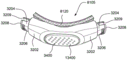
Fig. 3A illustrates a patient interface in the form of a nasal mask in accordance with one form of the present technique.
Fig. 3B shows a schematic diagram of a cross-section through a structure at one point. The outward normal at that point is indicated. The curvature at this point has a positive sign and a relatively large magnitude when compared to the magnitude of the curvature shown in fig. 3C.
Fig. 3C shows a schematic diagram of a cross-section through a structure at one point. The outward normal at that point is indicated. The curvature at this point has a positive sign and a relatively small magnitude when compared to the magnitude of the curvature shown in fig. 3B.
Fig. 3D shows a schematic diagram of a cross-section through a structure at one point. The outward normal at that point is indicated. The curvature at this point has a value of zero.
Fig. 3E shows a schematic diagram of a cross-section through a structure at one point. The outward normal at that point is indicated. The curvature at this point has a negative sign and a relatively small magnitude when compared to the magnitude of the curvature shown in fig. 3F.
Fig. 3F shows a schematic diagram of a cross-section through a structure at one point. The outward normal at that point is indicated. The curvature at this point has a negative sign and a relatively large magnitude when compared to the magnitude of the curvature shown in fig. 3E.
Fig. 3G shows a cushion for a mask comprising two pillows. The outer surface of the mat is indicated. The edges of the surface are indicated. Dome and saddle regions are indicated.
Fig. 3H shows a cushion for a mask. The outer surface of the mat is indicated. The edges of the surface are indicated. The path on the surface between point a and point B is indicated. The straight-line distance between point a and point B is indicated. Two saddle regions and one dome region are indicated.
Fig. 3I shows the surface of a structure with one-dimensional holes in the surface. The planar curves shown form the boundaries of one-dimensional apertures.
Fig. 3J shows a cross-section through the structure of fig. 3I. The surfaces shown define two-dimensional pores in the structure of fig. 3I.
FIG. 3K shows a perspective view of the structure of FIG. 3I, including two-dimensional holes and one-dimensional holes. Also shown are the surfaces that define the two-dimensional apertures in the structure of fig. 3I.
Fig. 3L shows a mask with an inflatable bladder as a cushion.
Fig. 3M shows a cross-section through the mask of fig. 3L and shows the inner surface of the balloon. The inner surface defines a two-dimensional aperture in the mask.
Fig. 3N shows another cross-section through the mask of fig. 3L. The inner surface is also indicated.
Fig. 3O shows the left-hand rule.
Fig. 3P shows a right-hand rule.
Fig. 3Q shows the left ear including the left ear spiral.
Fig. 3R shows a right ear including a right ear helix.
Fig. 3S shows a right-hand helix.
Fig. 3T shows a view of the mask including a twisted sign of the spatial curve defined by the edges of the sealing membrane in different regions of the mask.
Fig. 3U shows a view of the plenum chamber 3200 showing the sagittal plane and the intermediate contact plane.
Figure 3V shows a view of the rear of the plenum of figure 3U. The direction of the view is perpendicular to the middle contact plane. The sagittal plane in fig. 3V divides the plenum chamber into left and right sides.
Figure 3W shows a cross-section through the plenum chamber of figure 3V, taken at the sagittal plane shown in figure 3V. Showing the 'middle contact' plane. The medial contact plane is perpendicular to the sagittal plane. The direction of the medial contact plane corresponds to the direction of the chord 3210, which lies on the sagittal plane and just contacts the cushion of the plenum chamber at the following two points on the sagittal plane: an upper point 3220 and a lower point 3230. Depending on the geometry of the mat in this region, the middle contact plane may be tangent at both the upper and lower points.
Fig. 3X shows the plenum chamber 3200 of fig. 3U in a use position on the face. When the plenum chamber 3200 is in the use position, the sagittal plane of the plenum chamber generally coincides with the median sagittal plane of the face. The intermediate contact plane generally corresponds to the 'face plane' when the plenum is in the use position. In fig. 3X, plenum chamber 3200 is a plenum chamber of a nasal mask, and upper point 3220 is located approximately at the point of the nasal bridge, while lower point 3230 is located on the upper lip.
4.4 RPT device
Fig. 4A illustrates an RPT device in accordance with one form of the present technique.
4.5 patient interface according to the current technology
Fig. 5 is a perspective view of a patient interface in accordance with an example of the present technology worn by a patient.
Fig. 6 is a perspective view of another example patient interface worn by a patient in accordance with the present technology.
Fig. 7 is a cross-sectional view of the positioning and stabilizing structure taken along line 7-7 of fig. 6.
Fig. 8 is an enlarged view of a portion of the positioning and stabilizing structure of fig. 7.
Fig. 9 is an enlarged view of a portion of the positioning and stabilizing structure of fig. 7.
FIG. 10 is a front view of the cushion assembly of FIG. 5 positioned on a patient's face.
FIG. 11 is a front view of the cushion assembly of FIG. 5.
FIG. 12 is a top perspective view of the cushion assembly of FIG. 5.
FIG. 13 is a top view of the cushion assembly of FIG. 5.
FIG. 14 is a side view of the cushion assembly of FIG. 5.
FIG. 15 is a front view of the cushion assembly of FIG. 5.
FIG. 16 is a side view of the cushion assembly of FIG. 5.
FIG. 17 is a top view of the cushion assembly of FIG. 5.
FIG. 18 is a front view of a cushion assembly positioned on a patient's face in accordance with another example of the present technique.
FIG. 19 is a top view of the cushion assembly of FIG. 18.
FIG. 20 is a front view of the cushion assembly of FIG. 18.
Fig. 21 is a bottom view of the pad assembly of fig. 18.
FIG. 22 is a side perspective view of the cushion assembly of FIG. 18.
FIG. 23 is a front view of a cushion assembly according to another example of the present technique.
FIG. 24 is a bottom perspective view of the cushion assembly of FIG. 23.
FIG. 25 is a side perspective view of the cushion assembly of FIG. 23.
FIG. 26 is a top perspective view of the cushion assembly of FIG. 23.
FIG. 27 is a rear perspective view of the cushion assembly of FIG. 23.
FIG. 28 is a top perspective view of a cushion assembly according to another example of the present technique.
FIG. 29 is a front view of the cushion assembly of FIG. 28.
FIG. 30 is a side perspective view of the cushion assembly of FIG. 28.
FIG. 31 is a rear perspective view of the cushion assembly of FIG. 28.
Fig. 32 is a bottom view of the pad assembly of fig. 28.
FIG. 33 is a front perspective view of a cushion assembly according to another example of the present technique.
FIG. 33-1 is a front perspective view of a cushion assembly according to another example of the present technique.
Fig. 33-2 is a cross-sectional view taken along line 33-2-33-2 in fig. 33-1.
Fig. 33-3 is a cross-sectional view taken along line 33-3-33-3 in fig. 33-1.
Fig. 33-4 is an enlarged detail view of a portion of fig. 33-2.
FIG. 34 is a cross-sectional view of the cushion assembly of FIG. 33.
Fig. 34-37 are front perspective views of a gasket subassembly having grip pads disposed on a fabric membrane in accordance with examples of the present technique.
Fig. 38 is a perspective view of a patient interface according to another example of the present technology worn by a patient.
Fig. 39 is a perspective view of a patient interface in accordance with another example of the present technique.
Fig. 40 is a perspective view of the patient interface of fig. 39 being worn by a patient.
Fig. 41 is a side view of the patient interface of fig. 40.
Fig. 42 is a front perspective view of the patient interface of fig. 40.
Fig. 43 is a front view of a cushion assembly of the patient interface of fig. 39.
FIG. 44 is a top view of the cushion assembly of FIG. 39.
Fig. 45 is a bottom view of the pad assembly of fig. 39.
FIG. 46 is a front perspective view of the cushion assembly of FIG. 39.
FIG. 47 is a rear perspective view of the cushion assembly of FIG. 39.
FIG. 48 is a side perspective view of the cushion assembly of FIG. 39.
FIG. 49 is a front perspective view of the cushion assembly of FIG. 39 showing the interior of the cushion assembly.
FIG. 50 is a front view of the cushion assembly of FIG. 39 showing the interior of the cushion assembly.
FIG. 51 is a rear view of an example cushion assembly according to the present technique.
FIG. 52 is a front view of the cushion assembly of FIG. 51.
FIG. 53 is a cross-sectional view of the cushion assembly of FIG. 51.
Fig. 54-56 are front perspective views of a gasket subassembly having grip pads disposed on a fabric membrane in accordance with examples of the present technique.
Fig. 57 is a perspective view of a patient interface 30000 in accordance with an example of the present technology.
Fig. 58 is a perspective view of the patient interface 30000 of fig. 57 as worn by a patient.
Fig. 59 is a cross-sectional view of the patient interface 30000 shown in fig. 57.
Fig. 60 is a side view of the patient interface 30000 of fig. 57 as worn by a patient.
FIG. 61 is a front perspective view of the cushion assembly 30105 of FIG. 57.
FIG. 62 is a rear perspective view of the cushion assembly 30105 of FIG. 57.
Fig. 63 is a front view of the frame 30350 of fig. 57.
Fig. 64 is a rear view of the frame 30350 of fig. 57.
Fig. 65 is a rear view of the patient interface 30000 of fig. 57 as worn by a patient.
Fig. 66 is a view of the strap of the positioning and stabilizing structure 30300 of the patient interface 30000 of fig. 57.
Fig. 67 is a perspective view of a patient interface of another example worn by a patient in accordance with the present technology.
Fig. 68 is a side view of the patient interface of fig. 67.
FIG. 69 is an exploded view of the patient interface shown in FIG. 67, showing the cushion assembly, frame assembly, arm cover and elbow assembly;
FIG. 70 is a front exploded view of an example cushion assembly according to the present technique.
FIG. 71 is a rear exploded view of the cushion assembly of FIG. 70.
Fig. 72 is a front view of a cushion assembly of the patient interface of fig. 67.
FIG. 73 is a front perspective view of the cushion assembly of FIG. 72.
FIG. 74 is a rear perspective view of the cushion assembly of FIG. 72.
FIG. 75 is a top perspective view of the cushion assembly of FIG. 72.
FIG. 76 is a bottom perspective view of the cushion assembly of FIG. 72.
FIG. 77 is a side perspective view of the cushion assembly of FIG. 72.
Fig. 78 is a schematic illustration of a process of providing a fabric material with an air impermeable layer, in accordance with an example of the present technique.
Fig. 79 is a schematic diagram depicting a patient's face being presented to a fabric membrane with slight tension prior to use.
Fig. 80 is a schematic diagram illustrating the resultant force exerted by the fabric membrane on the patient's face due to tensile stress in the fabric membrane.
FIG. 81 is a schematic view of tension applied to a sealing portion of a cushion assembly in accordance with an example of the present technique.
FIG. 82 is a schematic view of the force exerted by the fabric membrane on the patient's face due to the air pressure within the cavity formed by the cushion assembly.
FIG. 83 is a cross-sectional view of an example cushion assembly in accordance with the present technique.
FIG. 84 is a cross-sectional view of an exemplary cushion assembly according to the present technique.
FIG. 85 is a cross-sectional view of an example cushion assembly in accordance with the present technique.
FIG. 86 is a cross-sectional view of an example cushion assembly according to the present technique.
FIG. 87 is a partial cross-sectional view of a sealing portion and a support structure of a cushion assembly having an outer offset portion in accordance with examples of the present technique.
FIG. 88 is a partial cross-sectional view of a sealing portion and a support structure of a cushion assembly having an internally biased portion in accordance with an example of the present technique.
FIG. 89 is a partial cross-sectional view of an example cushion assembly according to the present technique.
FIG. 90A is a partial cross-sectional view of an example cushion assembly according to the present technique.
FIG. 90A-1 is an enlarged view of a portion of the sealing portion of the cushion assembly of FIG. 90A.
FIG. 90B is a partial cross-sectional view of an example cushion assembly according to the present technique.
FIG. 91 is a partial cross-sectional view of an example cushion assembly according to the present technique.
FIG. 92 is a partial cross-sectional view of an example cushion assembly according to the present technique.
FIG. 93 is a partial cross-sectional view of an example cushion assembly according to the present technique.
FIG. 94 is a partial cross-sectional view of an example cushion assembly according to the present technique.
FIG. 95 is a partial cross-sectional view of an example cushion assembly according to the present technique.
FIG. 96 is a partial cross-sectional view of an example cushion assembly according to the present technique.
FIG. 97 is a partial cross-sectional view of an example cushion assembly according to the present technique.
FIG. 98 is a partial cross-sectional view of an example cushion assembly according to the present technique.
FIG. 99 is a partial cross-sectional view of an example cushion assembly according to the present technique.
FIG. 100 is a partial cross-sectional view of an example cushion assembly according to the present technique.
Fig. 101 is a cross-sectional view of a seal section modular assembly in accordance with an example of the present technique.
FIG. 102 is a partial cross-sectional view of a cushion assembly including the seal section modular assembly of FIG. 101 in accordance with an example of the present technique.
Fig. 103 is a perspective view of an exemplary modular support structure in accordance with the present technology.
Fig. 104 and 105 illustrate a process of molding a sealing portion to a support structure in accordance with examples of the present technique.
Fig. 106 is a side view of a seal segment modular assembly formed by the process shown in fig. 104 and 105.
Figures 107 and 108 illustrate a universal cushion assembly according to an example of the present technique.
Fig. 109 and 110 illustrate a customized cushion assembly manufactured by utilizing a three-dimensional contour obtained by scanning a patient's face, in accordance with an example of the present technique.
FIG. 111 is a front perspective view of a cushion assembly according to another example of the present technique.
FIG. 112 is a rear perspective view of the seal-forming structure of the cushion assembly of FIG. 111.
Fig. 113 and 114 depict a knitting process.
Fig. 115 shows an exemplary warp knit fabric according to the present technology.
FIG. 116 shows an exemplary weft knit fabric in accordance with the present technology.
Fig. 117 is a functional block diagram illustrating a process of overmolding a support structure onto a fabric composite to form a structure with a fabric membrane forming seal in accordance with examples of the present technique.
Detailed Description
Before the present technology is described in further detail, it is to be understood that this technology is not limited to the particular examples described herein, as the particular examples described herein may vary. It is also to be understood that the terminology used in the present disclosure is for the purpose of describing particular examples only and is not intended to be limiting.
The following description is provided in connection with various examples that may share one or more common features and/or characteristics. It should be understood that one or more features of any one example may be combined with one or more features of another example or other examples. Additionally, in any of the examples, any single feature or combination of features may constitute further examples.
5.1 treatment
In one form, the present technology includes a method for treating a respiratory disorder that includes the step of applying positive pressure to an entrance to the airway of a patient 1000.
In some examples of the present technology, a supply of air at positive pressure is provided to the nasal passages of a patient via one or both nostrils.
In certain examples of the present technology, mouth breathing is defined, restricted, or prevented.
5.2 treatment System
In one form, the present technology includes an apparatus or device for treating a respiratory disorder. The apparatus or device may comprise an RPT device 4000 for supplying pressurised air to a patient 1000 via an air circuit 4170 to a patient interface 3000, see for example fig. 1A to 1C.
5.3 patient interface
The non-invasive patient interface 3000 according to one aspect of the present technique includes the following functional aspects: a seal forming structure 3100, a plenum chamber 3200, a positioning and stabilizing structure 3300, a vent 3400, a form of connection port 3600 for connection to an air circuit 4170, and a forehead support 3700. In some forms, the functional aspects may be provided by one or more physical components. In some forms, one physical component may provide one or more functional aspects. In use, the seal forming structure 3100 is arranged to surround an entrance to the airways of a patient so as to facilitate the supply of air at positive pressure to the airways.
A patient interface may not be suitable for respiratory pressure therapy if it is unable to comfortably deliver a minimum level of positive pressure to the airway.
One form of patient interface according to the present techniquePort 3000 is constructed and arranged to provide at least 10cmH relative to the environment2And air is supplied at a positive pressure of O.
A patient interface 3000 according to one form of the present technique is constructed and arranged to provide at least 20cmH relative to the environment2And air is supplied at a positive pressure of O.
5.3.1 plenum Chamber
The plenum chamber has a perimeter which, in the area where the seal will be formed in use, is shaped to complement the surface contour of an average person's face. In use, the edges of the inflatable chambers are positioned very close to the adjacent surface of the face. The seal-forming structure provides physical contact with the face. The seal-forming structure may extend around the entire perimeter of the plenum chamber in use. In some forms, the plenum and the seal-forming structure are formed from a single homogeneous material.
5.3.2 seal formation
In one form of the present technique, the seal forming structure 3100 provides a target seal forming region, and may additionally provide a cushioning function. The target seal-forming region is a region on the seal-forming structure 3100 where a seal may occur. The area where sealing actually occurs-the actual sealing surface-may vary from day to day during a given treatment session and may vary from patient to patient depending on a number of factors including, for example, the position of the patient interface on the face, the tension in the positioning and stabilizing structure, and the shape of the patient's face.
In one form, the target seal-forming region is located on an outer surface of the seal-forming structure 3100.
In certain forms of the present technique, the seal-forming structure 3100 is constructed of a biocompatible material, such as Liquid Silicone Rubber (LSR) (or "silicone").
The seal forming structure 3100 in accordance with the present technique may be constructed of a soft, flexible, resilient material such as silicone.
In some forms, such as the form shown in fig. 5 to 77, the seal-forming structure has a sealing portion comprising a fabric material which may cover all or part of the seal-forming structure. In some forms, the fabric may comprise a material formed from a network of fibers and adapted to be air impermeable. For example, the fabric may have an air impermeable film on at least one surface thereof, thereby forming a fabric film or fabric sealing portion.
In some forms, the fabric membrane may be configured to elastically stretch in at least one dimension. For example, when the fabric membrane is constructed from a network of fibers, the fabric membrane can be elongated across the fabric membrane in the longitudinal warp direction and/or the transverse weft direction. In some forms, the fabric membrane is constructed such that it is elastically extensible to a greater degree than is possible with conventional silicone seals forming structures.
In certain forms, the fabric film is configured to be substantially inelastic in at least one dimension. For example, when the fabric membrane is constructed of a woven fabric material, the fabric membrane is capable of substantially resisting elongation in either or both of the longitudinal warp direction or the transverse weft direction on the fabric membrane.
The fabric film may comprise a single layer or multiple layers. In utilizing multiple layers, the various layers may be formed using the same material or a variety of different materials each having unique material properties.
In some forms, the fabric membrane may include at least one layer that exhibits substantially air-impermeable characteristics while maintaining the material characteristics necessary to provide patient comfort and minimum pressure points. For example, as shown in fig. 78, in some forms, the fabric membrane may include an air impermeable material 10131 formed on an inner surface of the fabric material 10133. In some forms, the breathable material may be laminated to the fabric material. In some forms, the air impermeable material and the fabric material may be selected such that the resulting fabric film may exhibit a predetermined overall elasticity or elastic resistance as desired. For example, the addition of an air impermeable material (or film layer) may add elasticity (or stretchability) to the fabric material, such that the resulting fabric film has increased stretchability.
In some forms, the film may exhibit a low spring constant (i.e., high compliance) in both the warp and weft yarns. In such forms, unlike conventional designs in which the mounting pad may cause skin torsion of the patient's face 1300 to form an effective seal, the fabric material and/or the resulting fabric membrane may have a material spring constant and spring length such that the fabric membrane is more compliant than the patient's skin engaging the fabric membrane. This may advantageously improve the comfort of the mask and reduce the formation of local pressure "hot spots".
In some forms, the surface of the fabric material that contacts the patient's face 1300 may have low friction characteristics. This may advantageously improve the comfort of the surface texture of the fabric membrane and reduce friction against the patient's face 1300. The fabric material may have a surface (e.g., chevron belt) having a first coefficient of friction in a first direction that is different from (e.g., greater than or less than) a coefficient of friction in a second direction. Conversely, in use, a higher friction fabric may cause the fabric membrane to grip or rub against the contact area of the patient's face. Such rubbing or gripping may cause the fabric membrane to distort or deform, thereby reducing the effectiveness of the seal and allowing air to undesirably leak from the device.
In some forms, the fabric material of the fabric membrane may have a total thickness of 0.275mm or less.
In some forms of the present technology, a system is provided that includes more than one seal forming structure 3100, each seal forming structure configured to correspond to a different range of sizes and/or shapes. For example, the system may include one form of seal forming structure 3100 that is suitable for large size headers but not for small size headers, and another form of seal forming structure that is suitable for small size headers but not for large size headers.
It should be noted that although the description may refer (e.g., by reference characters) to particular illustrated examples or features of particular illustrated examples (e.g., seal-forming structure 3100), such discussion may be applicable to other examples and/or features (e.g., seal-forming structure 5100).
5.3.2.1 sealing mechanism
In one form, the seal forming structure includes a sealing flange that utilizes a pressure assisted sealing mechanism. In use, the sealing flange may readily respond to a positive system pressure inside the plenum chamber 3200, which acts on its underside to urge the sealing flange into tight sealing engagement with the face. The pressure assist mechanism may act in the positioning and stabilising structure together with the elastic tension.
In one form, the seal forming structure 3100 includes a sealing flange and a support flange. The sealing flange comprises a relatively thin member having a thickness of less than about 1mm, for example from about 0.25mm to about 0.45mm, that extends around the perimeter of the plenum chamber 3200. The support flange may be relatively thicker than the sealing flange. The support flange is disposed between the sealing flange and the edge of the plenum chamber 3200 and extends at least a portion of the way around the perimeter. The support flange is or includes a spring-like element and acts to support the sealing flange against bending in use.
In one form, a fabric membrane (e.g., comprising nylon, polyester, nylon and polyester blends, microfibers, or polyurethane) is used as the face-contacting portion of the CPAP mask's seal-forming structure 3100. The fabric membrane may have properties such that it is capable of being elongated in at least one dimension. The fabric membrane may be held under tension across the support structure prior to and/or during use. Prior to use, the fabric membrane may be permanently attached (e.g., molded) or attached to the support structure as a removable module such that it is pre-tensioned and slightly stretched.
Alternatively, the fabric may be formed into a complex three-dimensional predetermined shape such that the fabric is not tensioned (e.g., loosened, relaxed, and/or wrinkled) prior to and/or during use, but does not substantially leak causing wrinkles. Due to manufacturing, the fabric polymer may shrink such that the pre-tension inherent in the fabric membrane is lost, yet the fabric membrane may remain substantially wrinkle-free.
Fig. 79 shows an example in which the fabric membrane has slight tension in both the X and Y directions in the fabric surface. The fabric membrane is adapted to form a constant surface before the patient's face 1300 (such as the nose) approaches and depresses the fabric membrane 3130, without creating interruptions, such as wrinkles, creases, or folds, in the fabric material prior to contact between the patient's face 1300 and the seal-forming structure 3100. In some forms, this may be achieved by applying a slight pretension or by molding the fabric membrane so that it is substantially free of any leakage that causes wrinkles. This may be advantageous to ensure that the fabric membrane forms a smooth and continuous seal on and around the patient's face 1300. This may provide improved respiratory pressure treatment by reducing the occurrence of folded or wrinkled portions of the seal forming structure 3100 through which treatment air may leak. This may also be advantageous to ensure that the fabric membrane remains below a minimum tension threshold when the fabric membrane is pressed against the patient's face 1300 (fig. 80).
In some forms, areas of the fabric film may be pre-tensioned and stretched slightly while other areas of the fabric film may remain relaxed. For example, in some forms, the sub-nasal region may be pre-tensioned, while the region covering the nares and/or outside of the patient's mouth may remain untensioned (e.g., due to excess material) so as to form a saddle-shaped region or valley-shape prior to use. This may advantageously improve sealing efficiency while reducing pressure (i.e., "hot spots") on areas of the facial anthropometry that protrude a greater distance into or toward the cavity. In another example, the sides of the nose region and/or nasal bridge region may remain untensioned and/or relaxed prior to use to provide additional material to accommodate the facial contours of these sensitive facial regions. In another example, prior to use, the bridge portion (e.g., bridge portion 3104) extending between the two nostril openings may be tensioned, relaxed by excess material, and/or bent, as shown, for example, in fig. 33-1. Having a bridge portion (e.g., 3104) of excess material may allow the fabric membrane to expand (e.g., in the superior-inferior (height) direction) to accommodate different sized noses.
In some forms, instead of having pre-tensioned regions, the fabric membrane may be formed to be substantially free of leaks that cause wrinkles. This may be advantageous because it may be difficult to form complex three-dimensional shapes that are substantially leak-free from loose fabric films or from fabric films with excess non-tensioned material. In some arrangements, the untensioned fabric membrane may be more comfortable because it may apply less pressure to the patient's face.
In some forms, the fabric membrane may be in a substantially tensionless state and formed on a support structure or directly on a plenum in a manner that remains untensioned and/or relaxed. In one example, such a fabric membrane may remain uncreped in order to avoid the formation of leaks in the seal with the patient's face. In some forms, the untensioned and/or non-wrinkled fabric membrane may enable an effective seal with the patient's face using a cushion support (e.g., an underlying cushion, a seal support region (e.g., a support structure), and/or air pressure within the cavity).
In some forms, a taut and/or non-wrinkled state in the fabric membrane may be maintained (see fig. 80 and 81) so as to maintain sealing contact with the patient's face 1300 by one or a combination of:
a) Pre-applied tensile stress of the fabric membrane and additional applied tensile stress when the patient's face 1300 engages the fabric membrane;
b) formed as a pre-form of the untensioned, but substantially constant surface, fabric film without leaks causing discontinuities such as wrinkles, creases, bends, or folds in the fabric film.
c) The stiffness of the support structure and/or plenum chamber, and the ability of the support structure and/or plenum chamber to accommodate and react to applied tensile stresses when the patient's face 1300 engages the fabric membrane; and
d) the air pressure from the cavity applies an additional load to the inner surface of the fabric membrane. The internal air pressure may apply additional tensile stress to the inner surface of the fabric membrane in order to further stretch and stress the fabric membrane against the patient's face 1300 (e.g., to form a pressure assisted seal).
By continuously maintaining the fabric membrane under tensile stress and/or in a non-wrinkled state prior to and during use, the fabric membrane may conform to the contours of the patient's face while minimizing wrinkling and/or blow-out of the seal-forming structure. In some forms, this may also improve sealing performance by maximizing the contact area of the fabric membrane on the patient's face 1300. In some forms, this may also improve the performance of the CPAP device when it is subjected to external lateral or longitudinal forces (e.g., tube resistance).
In some forms, the applied load from the air pressure within the plenum may help the fabric membrane maintain an effective seal when the plenum is pulled a short distance away from the patient's face 1300. The applied load of air pressure may be sufficient to cause the fabric membrane to elastically stretch in at least one dimension such that it creates a balloon-like "hovercraft" effect on the anthropometric contours of the patient's face 1300, thus maintaining an effective seal thereon.
In some forms, the fabric membrane may be held under tension by a relatively stiff support structure. In various forms, the support structure may be formed from any one of, for example, silicone, PU foam, PU solid material, or other suitable material. In some forms, the support structure may be relatively less rigid than the housing or frame of the plenum.
In some forms, the magnitude of the tensile stress may vary across the fabric membrane of the seal-forming structure as desired. For example, there may be stress concentration areas near one or more holes in the fabric membrane through which treatment is performed or in wider material stretches.
In some forms, the seal-forming structure may utilize many different cushion configurations, including a single air-assisted fabric membrane, a dual air-assisted fabric membrane, a fabric membrane with a compression bracket, or a fabric membrane with a TPU/TPE/Si bracket. In some forms, the mat configuration of the seal-forming structure may be formed such that it may advantageously provide a "universal size" solution.
In examples, forming the sealing structure and inflation chamber may be applied to nasal cushions, nose pads, oronasal cushions, ultra-compact full face masks, and other suitable cushion arrangements.
In some forms, the fabric membrane may be configured to create an effective seal over the patient's nasal papillary sites, for example as shown in fig. 58. In some forms, the fabric membrane may be configured to create an effective seal against the inferior septum portion of the patient's nose such that the fabric membrane does not engage the nasal relief, for example as shown in fig. 40.
In some forms, stretching the fabric membrane and/or maintaining an unfolded state of the fabric membrane to conform to the patient's face 1300 may, in use, exert stress on the walls of the support structure. In use, the stress may pull the walls of the support structure inwardly towards each other. In some forms, the support structure may be adapted to resist an applied stress load so as to prevent inward deformation. Thus, in use, the rigidity of the support structure may apply further stress to the fabric membrane, which in turn may cause elastic stretching of the fabric membrane.
In some forms, such as the form shown in fig. 87 and 88, the support structure may include a crease, fold, or gusset (e.g., seal biasing portions 10140, 10140') that dynamically supports the fabric membrane with internal air pressure. This may advantageously provide further support to the fabric membrane when under dynamic loading (e.g., tube resistance). In other forms, the corrugations, creases, or gussets may utilize internal air pressure to separate dynamic loads (e.g., tube resistance) from the seal-forming structures. In some forms, the air pressure within the cavity may apply a load to the inner surface of the fabric membrane to create further tensile stress such that the fabric membrane substantially fills the concave contours of the patient's face 1300 (e.g., around the sides of the nose). In some forms, the elasticity of the fabric membrane, when combined with the applied load of internal air pressure, may elastically stretch the fabric membrane such that it forms a larger sealing contact area on the patient's face. In some forms, this may be advantageous to provide a continuous seal even if the mask is removed from optimal engagement with the patient's face, as the fabric film may partially inflate due to the reactive force created by the internal air pressure (i.e., the "hovercraft effect").
In some forms, such as those shown in fig. 35-37 and 54-56, the fabric membrane may have one or more grip pads 29150, 31150 disposed thereon. In one example, the grip pads 29150, 31150 may be configured to be substantially flat along the patient-facing surface of the fabric membrane. In other examples, the grip pads 29150, 31150 may be embossed such that the grip pads may form beads or edges that protrude slightly above the surface of the fabric membrane. In some forms, the grip pads 29150, 31150 may have a high coefficient of friction. In some forms, the gripping pad may have a defined shape (e.g., oval (see fig. 35, 37, 54, and 56), circular, square, etc.). In some forms, the gripping pad may be elongated (see fig. 35 and 54). In some forms, the grip pads 29150, 31150 may be linear. In some forms, the grip pads may be arranged in some pattern on the surface of the seal forming structure 3100. In some forms, the gripping pads may be sporadically disposed on the surface of the seal forming structure 3100 (see fig. 37 and 56). In some forms, the gripping pad may be arranged to form a perimeter near the peripheral edge of the fabric membrane (see fig. 34, 35, 54, and 55). In some forms, the grip pads 29150, 31150 forming the perimeter may be in the form of dashed lines (see fig. 35 and 54). In some forms, the gripping pad forming the perimeter may be in the form of a solid line (see fig. 36 and 55). In some forms, the gripping pad forming the perimeter may be in the form of a plurality of lines, a dotted line, or a solid line, or a combination thereof. In some forms, the grip may assist the fabric membrane in gripping the patient's face. In one example, the gripping pad is formed as a relatively thin silicone layer applied to the surface of the fabric membrane.
In some forms, the fabric membrane may be integral with the support structure by attaching (e.g., molding) an outer edge (e.g., outer perimeter) of the fabric membrane around a lip of a curved edge (i.e., inner edge) of the support structure. In one example, the fabric membrane may be angled slightly "inward" toward the mask interior. In one example, a fabric membrane is attached to provide the front side of the seal-forming structure. That is, the support structure forms a portion of the seal forming structure that is bent from the front side to the rear surface contact side of the seal forming structure (see fig. 11). In this way, the fabric membrane can avoid having portions that curve from the back side to the front side. With this arrangement, the fabric membrane may be present only along the front side of the seal-forming structure, for example as shown in fig. 11 to 17. This arrangement may be advantageous because the fabric membrane may not need to be folded or cut to fuse around the corners of the support structure. This may be advantageous to reduce the occurrence of protruding creases or wrinkles in the fabric membrane (which may cause leakage), thereby improving the performance of the seal.
In some forms, the fabric membrane may be attached to an outer edge of the fabric membrane such that the fabric membrane forms a portion of the seal-forming structure that curves from the front side to the back contact side of the seal-forming structure (see, e.g., fig. 33-1 to 33-4, 73, and 74). This may present more of the fabric membrane surface (rather than the support structure) to engage with the patient's face, which may improve comfort. In one example, attaching the fabric membrane to the support structure through a particular process (as described below) can form the curved portion without forming creases, wrinkles, folds, or bends on the surface of the fabric membrane. It can be seen that in some examples, at the transition portion 36, both the support structure and the fabric membrane may have a radius of curvature (e.g., the same or similar radius of curvature) along the curve 35 in a direction from the front side of the seal-forming structure to the back side of the seal-forming structure (see fig. 33-1 to 33-4). The fabric membrane may be given a predetermined curvature such that a portion of the fabric membrane not directly supported by the support structure extends along a curved line 35 (fig. 33-2 to 33-4). This can help form a dome shape (e.g., a convex dome) in certain areas of the fabric membrane (e.g., sides 3250 and/or corner areas 3252), which can help the fabric membrane seal against the contours of the patient's face (e.g., the subperion of the patient's face (i.e., the corners of the nasal area (i.e., the areas where the alars terminate near the upper lip near the nasolabial sulcus))), for example, as shown in fig. 33-1. The dome shape may help prevent wrinkles, folds, creases, and bends from forming in the fabric membrane, which may help avoid forming leak paths. Also, the dome shape may help the fabric enter areas of the patient's face that are difficult to seal, such as the corners of the nasal region. The fabric membrane 29130 may have a saddle shape at a sub-nasal septum center region 3260 configured to seal against the patient's sub-nasal septum point, thereby matching the saddle shape formed by the patient's nasolabial angle and upper lip, as shown in fig. 33-1. Similarly, the nasal projection central region 3270 can also have a saddle shape configured to seal against a mating contour presented at or below the patient's nasal projection. The curvature (e.g., the amount and/or radius of curvature) of the fabric membrane in the direction of the curve 35 may vary in different regions of the cushion element along the periphery of the fabric membrane. For example, as shown in fig. 33-2, the fabric membrane 29130 may have a curvature in the direction of the curve 35 at the transnasal point central region 3270 that is different from its curvature in the direction of the curve 35 at the sub-nasal septum point central region 3260. In the example of fig. 33-2, the fabric membrane has a greater (e.g., smaller radius) curvature (e.g., negative curvature in the up-down direction along curve 35) at the transnasal point central region 3270 relative to its subnasal point central region 3260. In one example, the curvature (e.g., the amount of curvature and/or the radius of curvature) of the fabric membrane at the side 3250 can be different from its curvature at the central region of the pronasale point 3270 and/or the central region of the infraseptal point 3260. As shown, for example, in fig. 43, 52, and 61, the nose of the cushion assembly 14105, 30105, 31105 may have similar domed and saddle-shaped features.
In the example of fig. 73, the curvature of the fabric membrane 16230 from the connection with the support structure 16220 (e.g., at the transition) may continue to the inner edge of the fabric membrane. For example, the fabric membrane may have a dome shape or saddle shape at the inner edge of the fabric membrane in certain areas of the cushion.
In some forms, the fabric membrane may be slightly inwardly sloped or curved (e.g., with positive curvature in the left-right direction) toward the mask interior, for example, as shown in fig. 11-17, 23-26, and 33-37. In some forms, the fabric membrane may form a dome shape over the support structure, for example as shown in fig. 19-22 and 43-50. Note that any of the cushion assemblies disclosed herein may have a webbing attached to the outer edge of the webbing such that the webbing forms a portion of the seal-forming structure that extends along a curve 35 from the front side of the seal-forming structure to the rear contact face as discussed above with reference to fig. 33-1, such that, for example, the webbing 6130 of the cushion assembly 6105 may assume a dome shape to a greater extent with a greater degree of convexity from one side to the other.
In some forms, if the fabric film is not under constant tension (before and/or during use) or is not elastic, the fabric film may form an improved air-assisted seal on the patient's face to dynamically conform to changes/movements due to the fabric film being thinner and less structurally rigid than the silicone film (e.g., the "hovercraft effect").
In some forms, the fabric membrane may be supported by a second or third support structure that may serve as a cushion support. The cushion support may provide additional flexibility and may be adapted for use on most patient faces (universal size). The second or third support layer may be formed using a film of fabric, fabric with PU/Si film, laminated open-cell foam, laminated PU foam, PU molding, TPU/TPE or silicone. In some forms, the additional support layer itself may be supported by a structural/rigid plastic such as PP/PC/PA/PET or other suitable material.
In some forms, 3D printing of the fabric membrane and/or cushion support as a "skeleton" may reduce the thickness and thus the weight of the mask.
In some forms, multiple different layers of the mask layer may be printed with different rigidities, hardnesses, or thicknesses. For example, the "backbone" portion may be formed using Si, PU foam, PU solid material, or any suitable plastic material.
In some forms, wrinkles or folds may be formed along the cushion element (e.g., in the fabric membrane and/or support structure) that may provide dynamic force/support or decoupling regions.
In one form, the seal forming structure may include a compression seal portion or a gasket seal portion. In use, the compression seal portion or gasket seal portion is constructed and arranged to be in compression, for example, due to elastic tension in the positioning and stabilizing structure.
In one form, the seal-forming structure includes a tensioning portion. In use, the tensioning portion is held in tension, for example by adjacent regions of the sealing flange.
In one form, the seal-forming structure includes a region having an adhesive or cohesive surface.
In some forms of the present technique, the seal-forming structure may include one or more of: pressure assisted sealing flanges, compression sealing portions, gasket sealing portions, tensioning portions, and portions having adhesive or cohesive surfaces.
5.3.2.2 nose post or nasal bridge region
In one form, the non-invasive patient interface 3000 includes a seal-forming structure that, in use, forms a seal on the nasal post region or nasal bridge region of the patient's face.
In one form, the seal-forming structure includes a saddle-shaped region configured to form a seal on a nasal post region or a nasal bridge region of the patient's face in use.
5.3.2.3 upper lip region
In one form, noninvasive patient interface 3000 includes a seal-forming structure that, in use, forms a seal on the upper lip region (i.e., upper lip) of a patient's face.
In one form, the seal-forming structure includes a saddle-shaped region configured to form a seal on an upper lip region of a patient's face in use.
5.3.2.4 chin area
In one form, noninvasive patient interface 3000 includes a seal-forming structure that, in use, forms a seal over the chin region of a patient's face.
In one form, the seal-forming structure includes a saddle-shaped region configured to form a seal on a chin region of a patient's face in use.
5.3.2.5 forehead region
In one form, the seal-forming structure forms a seal over a forehead region of a patient's face in use. In this form, the plenum chamber may cover the eye in use.
5.3.2.6 nasal pillow
In one form, the seal-forming portion of the non-invasive patient interface 3000 includes a pair of nasal puffs or pillows, each constructed and arranged to form a seal with a respective nostril of the patient's nose.
A nasal pillow according to one aspect of the present technology includes: a frustoconical body, at least a portion of which forms a seal on the underside of the patient's nose; a handle; a flexible region on the base of the truncated cone and connecting the truncated cone to the stem. In addition, the structure to which the nasal pillows of the present technology are attached includes a flexible region adjacent the bottom of the handle. The flexible regions may act together to facilitate a universal joint arrangement that can accommodate relative movement both with displacement and angle between the structure to which the frustoconical body and nasal pillows are connected. For example, the position of the frustoconical body may be moved axially toward the structure to which the shank is connected.
5.3.3 nasal cushion
Referring to fig. 5 to 14, there is shown a patient interface 3000, 6000 with a cushion assembly 3105 comprising a seal forming structure 3100 and a plenum chamber 3200 in accordance with a first example of the present technique. Fig. 15-17 illustrate a cushion assembly 5105 including a seal-forming structure 5100 and a plenum chamber 3200 in accordance with a second example of the present technique. Figures 18 to 22 show a third example of a mattress assembly 6105 that includes a seal-forming structure 6100 and a plenum chamber 3200 in accordance with the present technique. Figures 23 to 27 show a cushion assembly 7105 according to a fourth example of the present technology, comprising a seal-forming structure 7100 and a plenum chamber 3200. Referring to fig. 28 to 32, there is shown a mattress assembly 8105 according to a fifth example of the present technology, including a seal-forming structure 8100 and a plenum chamber 3200. Fig. 3 illustrates a patient interface 9000 with a cushion assembly 9105 comprising a seal-forming structure 9100 and a frame 9200 according to a sixth example of the present technology.
Fig. 11 to 14 include dashed lines demarcating regions of different thickness, and it should be understood that these are merely nominal boundaries, and not actual structures.
The examples of the seal forming structures 3100, 5100, 6100, 7100, 8100, 9100 described in the preceding paragraphs may be considered nose pads and are intended to provide a pressurized flow of gas to the nares of a patient by sealing against at least the underside of the patient's nose. Exemplary seal-forming structures may engage the patient's face below the nasal bridge, and depending on the size and shape of the patient's nose, some examples may engage the patient's nose below the nasal prominence. The example seal-forming structure may also engage the patient's face at least above the upper lip. Thus, the example seal-forming structure may seal against the patient's upper lip in use. Furthermore, the mouth of the patient may remain uncovered by the seal-forming structure of the depicted example, such that the patient may breathe freely, i.e. directly to the atmosphere, without interference from the seal-forming structure. The nose pad below the nose is configured to not have an opening sized to accommodate the patient's nose within the cavity. Further, the height of the nose pad from the lower edge of the fabric membrane in the central region of the inferior point of the nasal septum to the upper edge of the fabric membrane in the central region of the nasal projection point may be smaller than the width of the nose pad from one side edge of the fabric membrane to the other side edge of the fabric membrane in the left-right direction (see, for example, fig. 33 and 33-1).
Examples of nasal pillows (e.g., the example seal-forming structures disclosed herein) may include upper saddle or concave regions having positive curvature throughout the cushion. Also, a nasal tray may be understood to have a single target seal forming area or surface, while a nasal pillow may have two target seal forming areas (one for each nostril). The nasal cushion may also have a posterior wall that contacts the patient's upper lip and an upper central surface that contacts the underside of the patient's nose. The nasolabial sulcus angle may be formed between these two surfaces of the patient's face (see fig. 2E). The nose pad may be shaped to have a nasolabial angle in the range of 90 degrees to 120 degrees.
Further, the example seal-forming structures may also be shaped and sized such that no portion of the seal-forming structure enters the patient's nares during use.
Plenum chamber
Referring to figures 5 to 17, inflatable 3200 has a perimeter shaped to complement the surface contour of an average human face in the area where in use a seal will be formed. In use, the edges of the plenum chamber 3200 are positioned very close to the adjacent surface of the face. The seal forming structure 3100 provides the actual contact with the face. The seal forming structure 3100 may extend around the entire perimeter of the plenum chamber 3200 in use.
In certain forms of the present technology, the plenum chamber 3200 is constructed of a relatively rigid material (e.g., polycarbonate) as compared to the seal-forming structure. Alternatively, the plenum chamber 3200 may be constructed of a flexible material (e.g., silicone) and may be formed as a one-piece structure with a support structure (e.g., formed of any of the materials described herein as being suitable for the support structure and/or plenum chamber). In one example, the seal-forming structure may be an extension of the plenum or formed as part of the plenum such that the plenum contains the seal-forming structure. In this example, the support structure and the seal-forming structure may be part of a plenum. In another example, the plenum chamber 3200 may be constructed of a transparent material (e.g., transparent polycarbonate). The use of a transparent material may reduce the obstruction of the patient interface and help improve compliance with the therapy. The use of a transparent material may help the clinician observe the manner in which the patient interface is positioned and acted upon.
In certain forms of the present technology, the plenum chamber 3200 is constructed of a translucent material. The use of a translucent material may reduce the obstruction of the patient interface and help improve compliance with therapy.
Fig. 5 and 10 to 17 show an example of a seal forming structure 3100 having inflatable chambers 3200. The seal forming structure 3100 may comprise a plenum connection opening, wherein the seal forming structure 3100 is sealingly connected to the plenum chamber 3200. The seal forming structure 3100 and the plenum chamber 3200 may at least partially form a cavity 3101 that is pressurized by the flow of air. In the example shown, the seal-forming structure 3100 and the plenum chamber 3200 together form a cavity 3101.
The connection between the seal-forming structure 3100 and the plenum chamber 3200 at the plenum connection opening 3106 may be a permanent bond. The connection between the seal-forming structure 3100 and the plenum chamber 3200 at the plenum connection opening 3106 may be a chemical bond. The seal forming structure 3100 may be connected to the plenum chamber 3200 at the plenum chamber connection opening without a mechanical connection. Alternatively, the seal forming structure 3100 may be connected to the plenum chamber 3200 at the plenum chamber connection opening by a mechanically removable detachable connection.
On each side of the plenum chamber 3200, there may be a plenum side end 3202 in the form of a hollow channel that forms a plenum inlet aperture that is sized and configured to receive a flow of air. Plenum connectors 3204 may also be provided on each side of plenum 3200, laterally outward of plenum side ends 3202. The plenum connectors 3204 may be connected to respective ends 3314 of the positioning and stabilizing structure 3300. The connection between the plenum connectors 3204 and the respective ends 3314 of the positioning and stabilizing structure 3300 may be releasable on both sides. In other examples, one side may have a permanent connection and the other side may have a releasable connection. In further examples, both connections between the plenum connectors 3204 and the respective ends 3314 of the positioning and stabilizing structure 3300 may be permanent.
An end 3314 of the positioning and stabilizing structure 3300 may be connected to the plenum lateral end 3202. In these examples, each plenum connector 3204 may include a slot 3209, a chamfered edge 3208, and a notch 3206 that may be removably connected to a clamp of the positioning and stabilizing structure by a snap-fit.
The plenum chamber 3200 shown in fig. 18-32 in accordance with the third, fourth and fifth examples of the present technique may be similar or identical to the plenum chamber of fig. 10-17. It should also be appreciated that one or more aspects of the present technology may be combined with one or more of the following: U.S. provisional application No. 62/764, 992 entitled "Patient Interface" (patent Interface) filed on 20.8.2018 or PCT/AU2019/050873 filed on 20.8.2019, which are incorporated herein by reference in their entirety. For example, the plenum of the present technology may be the same as the plenum in any of the embodiments of the '992 or' 837 applications. Additionally, the seal-forming structures disclosed herein may replace any seal-forming structure in any patient interface disclosed in the '992 or' 873 applications, and the seal-forming structures of the present technology may include any feature of the seal-forming structures in any embodiment of the '992 or' 873 applications.
In the example of fig. 28-32, the plenum 13200 has a plenum side end 3202, a plenum connector 3204, a notch 3206, a chamfered edge 3208, and a slot 3209, similar to the plenum 3200 described above. However, the vent 3400 may be provided by a vent insert 13400 that is removably or permanently attached to the plenum 13200 (e.g., by insertion into an opening of the plenum). Note that any other example may have a vent insert (e.g., the vent 3400 in the plenum chamber 3200 of fig. 10-27 may be provided by a vent insert 13400 such as shown in fig. 28-32).
In the example of fig. 38, the frame 9200 can include a centered connection for the air circuit 4170. The frame may also include headband attachment portions 9210 at sides thereof. The seal-forming structure 9100 can be connected to the frame 9200 by spaced-apart connectors 9122, which can include clips on the seal-forming structure and receiving connectors on the frame.
Seal formation structure of the present technology
The seal-forming structures 3100, 5100, 6100, 7100, 8100, 9100, 29100 may each comprise a support structure 3120, 6120, 7120, 8120, 9120, 29120 that provides support to a sealing portion 3130, 5130, 6130, 7130, 8130, 9130, 29130 (e.g., a fabric membrane). The sealing portion is configured to sealingly engage a patient's face. Also, depending on the size and contour of the patient's nose, in the example of fig. 5-27, the support structure may also sealingly engage the patient's face.
Exemplary seal-forming structures 3100, 5100, 6100, 7100, 8100, 9100, 29100, although differing in various respects as described further below, may each include a support structure having at least two regions (e.g., two, three, or four regions) of differing thickness (e.g., seal-forming structure 3100 includes a support structure 3120 having a wall structure with lateral support regions 3122 of increased thickness relative to other portions of the wall structure). For example, as shown in fig. 59, portion of the support structure (d1) may be thicker than portion of the support structure (d 2). For example, portion (d1) may be adjacent or connected to the plenum chamber and portion (d2) may be adjacent or connected to the sealing portion to provide structural stability at the connection to the plenum chamber and flexibility at the interface with the patient. Optionally, thicker lateral support regions 3122 may be located, for example, at the nasal region corners of the seal-forming structure (and may, for example, be directly connected to the fabric membrane) to ensure that an adequate seal is formed in the rear upper flap region of the patient's face.
Further, in the depicted example, each sealing portion has two separate nostril openings 3102, one for each nostril of the patient, to provide airflow to both patient nostrils. The bridge portion 3104 may be located between the nostril openings 3102. The bridge portion 3104 may assist in providing a taut fabric membrane before and/or during use. In alternative examples, a single aperture may be used to provide airflow to both nostrils of a patient.
The seal forming structure 3100 as described above may comprise a plenum connection opening, wherein the seal forming structure 3100 is sealingly connected to the plenum chamber 3200. In the example of fig. 5-38, the support structures 3120, 5120, 6120, 7120, 8120, 9120, 29120 are directly connected to a plenum or frame. Thus, the support structure may comprise an opening where it is sealingly connected to the plenum chamber 3200.
The support structure may be less rigid than the plenum chamber 3200 and may be constructed of silicone, foam (e.g., polyurethane foam) (see fig. 28-32), polyurethane solid material, thermoplastic elastomer (e.g., thermoplastic polyurethane), suitable plastic, or other suitable material as described below. Further, the sealing portion may be less rigid than the support structure and may be constructed of a fabric material such as nylon, polyester, nylon and polyester blends, microfibers, or polyurethane, as will be described in more detail later. The seal portions described in any example of the present disclosure may be referred to as fabric seal portions or fabric films, and may include a fabric material having an air impermeable material laminated, coated, or otherwise applied thereon.
The support structure may have an aperture formed therein that provides an inner edge of the support structure along which a sealing portion (e.g., an outer perimeter of the sealing portion) may be attached to the support structure such that the sealing portion extends radially inward from the support structure beyond the support structure or to a greater extent than the support structure, for example, as shown in fig. 11-27 and 33-38. For example, the sealing portion may be molded around an inner edge of the support structure or connected to the support structure in other suitable ways, as will be described later. However, in alternative examples of fig. 28-32, the sealing portion 8130 may be laminated over the support structure 8120 (e.g., foam).
Referring to fig. 11-14, the seal forming portion 3100 has a wall structure that may include lateral support regions 3122 that are increased in thickness as compared to other portions of the wall structure of the support structure 3120. At each extreme side of the seal forming structure 3100, a lateral support region 3122 may be provided. The seal forming structure 3100 may comprise two lateral support regions 3122, each lateral support region being spaced apart from a distal end of a plane bisecting the seal forming structure 3100, which plane will be parallel to the sagittal plane of the patient in use. The lateral support region 3122 may be the thickest portion of the seal forming structure 3100 to provide resistance to lateral displacement, e.g., caused by a patient sleeping on their side, such that the nasal pillows push laterally against the seal forming structure and provide a secure engagement against the patient's alar nose. The lateral support region 3122 may have a thickness of about 0.9mm to about 1.5mm, or about 1.3mm to about 1.4mm, or about 1.3mm, or about 1mm to about 1.5 mm. Since the lateral support region 3122 is the thickest region of the seal forming structure 3100 in the depicted example, the lateral support region 3122 may also provide the greatest resistance to deformation.
In addition, the lateral support region 3122 may provide sufficient stiffness to ensure adequate sealing (e.g., by the lateral support region 3122) in the rear upper side panel region of the patient's face (i.e., the region where the alar terminates at the upper lip near the nasolabial sulcus), which is a particularly complex geometric region. The posterior upper lateral region of the patient's face presents a particularly complex geometry because at least three facial surfaces (the alar, upper lip, and cheek) converge in this region. Thus, sufficient rigidity in the lateral support region 3122 may ensure that the seal forming structure 3100 may be pushed into the rear upper panel region by a pulling force from the positioning and stabilizing structure 3300 without collapsing. The lateral support region 3122 may be located on the patient's face, in a region below the patient's alar and below and laterally outside the patient's nose, such as between the nasolabial sulcus and the upper lip region located below the alar.
The seal-forming structure 5100 in the example of fig. 15-17 may have a seal portion 5130 that expands as compared to the seal portion 3130 in fig. 11-14. That is, the support structure 5120 contracts and the sealing portion 5130 expands in the seal forming structure 5100 such that the sealing portion 5130 may be configured to engage the rear upper side panel region of the patient's face in use. As a result, the seal-forming structure 5100 may be more flexible and compliant to more easily conform to the contours of the patient's face.
Turning to fig. 18-22, the seal-forming structure in this example is arranged to provide a larger cavity 3101 such that the sealing portion 6130 protrudes further from the inflatable chamber in a direction towards the patient's face in use by creating greater tension in the sealing portion, thereby causing the sealing portion to expand outwardly. In use, the patient's nose can be pressed against the sealing portion 6130 in a direction toward the cavity 3101 and plenum chamber 3200, causing the sealing portion 6130 to stretch and invert such that the space formed by the cavity 3101 accommodates the patient's nose, thereby allowing the sealing portion 6130 to seal over the patient's nasal discharge, as shown in fig. 18. In contrast, as shown in fig. 10, the sealing portions 3130, 5130 seal under the patient's nasal prongs.
In the example of fig. 23-27, the sealing portion 7130 is also configured to seal over the nasal projection of the patient due to the height of the cushion. The sealing portion 7130 is configured to further seal in the upper lip red direction along the nasal bridge as compared to the sealing portion 6130.
In the exemplary cushion assembly of fig. 28-32, the support structure 8120 may be provided by a foam material laminated to the plenum chamber 3200. The sealing portion 8130 may be laminated directly to the support structure. The support structure 8120 may extend through the plenum connection opening, except for a pair of apertures formed therein (corresponding to the nostril openings 3102 in the sealing portion 8130). This arrangement may provide a compression-type seal against the patient's face, wherein the cushion assembly 8105 is drawn toward the patient's face by the headgear, thereby causing the seal-forming structure 8100 to conform to the contours of the patient's face by compression of the support structure 8120.
The cushion assembly 8105 is configured to seal against the underside of the patient's nose. The seal-forming structure 8100 includes an end 8122 that curves around the rear of the plenum chamber 3200 and is configured to engage the patient's upper lip in use.
Referring to fig. 33-37, the cushion element 29105 is similar to the cushion element 3105, but may extend further in the lateral left and right directions. The cushion assembly 29105 includes a seal-forming structure 29100, a support structure 29120, and a sealing portion 29130. Referring to fig. 33-1, the cushion element 29105-1 is similar to the cushion element 29105, but may have a fabric membrane 29105 formed such that the fabric membrane forms a portion of the seal-forming structure that curves from the front side to the back contact side of the seal-forming structure (as previously described).
As previously mentioned, fig. 35-37 show a grip pad 29150 on the surface of the fabric film.
In the example of fig. 38, the sealing portion 9130 is arranged to seal over the nasal papilla of the patient.
5.3.3.1 positioning and stabilizing Structure
The cushion assemblies 3105, 5105, 6105, 7105, 8105, 29105 of the patient interfaces 3000, 6000 of the present technology may be held in a sealed position in use by the positioning and stabilizing structure 3300. Cushion assembly 9105 of patient interface 9000 can be held in a sealed position in use by positioning and stabilizing structure 9300.
In one form, the positioning and stabilizing structures 3300, 9300 provide a retention force at least sufficient to overcome the positive pressure in cavity 3101 to lift off the face.
In one form, the positioning and stabilizing structure provides a retention force to overcome the effects of gravity on the patient interface.
In one form, the positioning and stabilizing structure provides a retention force as a safety margin to overcome potential effects of destructive forces on the patient interface, such as those due to resistance of the tube or accidental interference with the patient interface.
In one form of the present technology, a positioning and stabilizing structure 3300, 9300 is provided that is configured in a manner that is consistent with being worn by a patient while sleeping. In one example, the positioning and stabilizing structure has a smaller side or cross-sectional thickness to reduce the sensing or actual volume of the device. In one example, the positioning and stabilizing structure includes at least one strap that is rectangular in cross-section. In one example, the positioning and stabilizing structure includes at least one flat strap.
In one form of the present technology, a positioning and stabilizing structure is provided that is configured to be not too large and bulky to prevent a patient from lying in a supine sleep position and resting a rear region of the patient's head on a pillow.
In one form of the present technology, a positioning and stabilizing structure is provided that is configured to be not too large and bulky to prevent a patient from lying in a side sleeping position and resting a side region of the patient's head on a pillow.
In one form of the present technology, the positional stabilization structures 3300, 9300 are provided with a decoupling portion between the anterior portion of the positional stabilization structure and the posterior portion of the positional stabilization structure. The decoupling portion does not resist compression and may be, for example, a flexible band or a soft strap. The decoupling portion is constructed and arranged such that when a patient lays their head on the pillow, the presence of the decoupling portion prevents rearward forces from being transmitted along the positioning and stabilizing structure and breaking the seal.
In one form of the present technology, the positioning and stabilizing structure includes a strap constructed from a laminate of a fabric patient contacting layer, a foam inner layer, and a fabric outer layer. In one form, the foam is porous to allow moisture (e.g., sweat) to pass through the strap. In one form, the outer layer of fabric includes a loop material to engage portions of the hook material.
In some forms of the present technology, the positioning and stabilizing structure includes a strap that is extendable, such as elastically extendable. For example, the strap may be configured to be placed in tension during use and direct a force to bring the seal-forming structure into sealing contact with a portion of the patient's face. In one example, the strap may be configured as a lace.
In one form of the present technique, the positioning and stabilising structure includes a first strap that is constructed and arranged such that, in use, at least a portion of its lower edge passes over the cardinal point on the ear of the patient's head and covers a portion of the parietal bone, but not the occiput.
In one form of the present technology, which is applicable to either a nasal mask only or a full face mask, the positioning and stabilising structure includes a second strap that is constructed and arranged such that, in use, at least a portion of its upper edge passes under the infraotic basal point of the patient's head and overlies or underlies the occiput of the patient's head.
In one form of the present technology, which is applicable to either a nasal mask only or a full face mask, the positioning and stabilizing structure includes a third strap that is constructed and arranged to interconnect the first and second straps to reduce the tendency of the first and second straps to move apart from each other.
In some forms of the present technology, the positioning and stabilizing structure includes a strap that is bendable and, for example, non-rigid. The advantage of this aspect is that the strap makes it more comfortable for the patient to lie on while sleeping.
In some forms of the present technology, the positioning and stabilizing structure includes a strap configured to be breathable to allow moisture to be transmitted through the strap.
In some forms of the present technology, a system is provided that includes more than one positioning and stabilizing structure 3300, 9300, each configured to provide a retention force to correspond to a different range of sizes and/or shapes. For example, the system may include one form of locating and stabilizing structure that is suitable for large size heads but not for small size heads, while another form of seal-forming structure is suitable for small size heads but not for large size heads.
5.3.3.1.1 positioning and stabilizing structure of the present technology
Fig. 5 depicts an example of the present technology, which includes a positioning and stabilizing structure 3300. In this example, the positioning and stabilizing structure 3300 includes a transverse portion 3302 and an upper portion 3304 in the form of a conduit that directs the flowing pressurized gas from the hub 3306 to the end 3314. The positioning and stabilizing structure 3300 may be arranged such that, in use, the hub 3306 and decoupling structure 3500 are positioned higher than the patient's head. As described below, the decoupling structures 3500 can rotate within the hub 3306 and the position of the hub 3306 and decoupling structures 3500 above the patient's head allows the patient to move more freely without tangling with the air circuit 4170 when the patient interface 3000 is worn by the patient, e.g., during treatment.
The positioning and stabilizing structure 3300 may be constructed of silicone. For example, the transverse portion 3302, upper portion 3304, hub 3306, and side ends 3314 can be constructed or molded from a single piece of silicone.
The upper portion 3304 of the positioning and stabilizing structure 3300 has ridges and valleys (or hexagonal cross-sections) that allow the upper portion 3304 to conform to the shape of a corresponding portion of the patient's head in use. The ridges and valleys of upper portion 3304 allow upper portion 3304 to extend and retract along a longitudinal axis to accommodate larger or smaller heads. The ridges and valleys of the upper portion 3304 allow the upper portion 3304 to bend to different radii of curvature to accommodate different shapes and sizes of patient heads.
The lateral portion 3302 of the positioning and stabilizing structure 3300 may not be formed with the ridges and valleys of the upper portion 3304. Thus, the lateral portion 3302 may be less extensible and flexible than the upper portion 3304, which is advantageous because of less variability in the shape and size of the sides of the patient's head.
The positioning and stabilizing structure 3300 may be constructed and arranged to direct the force/tension provided by the transverse sections 3302 to force vectors applied to the upper and rear portions of the inflatable chamber 3200. The force vectors of the partial upper portion and the partial rear portion particularly urge the fabric membrane of the seal forming structure 3100 into sealing contact with the underside of the patient's nose, e.g., at or below the nasal projection and at least above the upper lip.
The transverse portions 3302 may also each include a tab 3308 that receives the rear strap end 3311 of the rear strap 3310. The back strap 3310 may be adjustable in length, for example, having a hook and loop material arrangement whereby one of the back strap end 3311 and the remainder of the back strap 3310 includes hook material on its exterior and the other includes loop material on its exterior. The adjustability in the length of the back strap 3310 allows for increased tension on the transverse portion 3302 to pull the seal forming structure 3100 into sealing engagement with the patient's face under a desired amount of pressure (i.e., tight enough to avoid leakage without being so tight as to cause discomfort).
The lateral section 3302 may also be provided with a sleeve 3312 that rests the patient's face against the lateral section 3302. The sleeve 3312 may be constructed of a breathable fabric material having a soft feel.
In an alternative example shown in fig. 6, the patient interface 6000 includes a positioning and stabilizing structure 6300 having at least one tube 6350 formed of a fabric material (e.g., one or more sheets or layers of fabric material) and receiving air from an air delivery tube 6348 via a connection port 6600. Tube 6350 includes left arm 6305 and right arm 6307.
In some forms, the fabric tube 6350 may be formed with a first side configured to contact the patient. This may be referred to as inner layer 6352. The fabric catheter may also include a second side that is attached to the inner layer, but faces away from the patient, which may be referred to as an outer layer 6354. The inner and outer layers may each be secured to one another along edges of the inner and outer layers such that a channel is formed between the seams of the inner and outer layers. That is, the space between the seams remains unattached and forms air channel 6372. The inner and outer layers may be joined using various techniques that impart special properties to the seam or joint. For example, in some forms, the seam is formed using ultrasonic welding, radio frequency welding, and cutting and welding techniques. Heat may be applied at specific areas to activate the thermoset or thermoplastic material used in tube 6350. This heat may be used not only to join the layers together, but also to thermoform the layers, such as the outer layer 6354. Further, in some forms, stitching or adhesives such as glue may be utilized to join the layers together. In some forms, no stitching is used. In a further form, material beyond the material in the layers is not used to connect the inner and outer layers of the tube. For example, in some forms, the inner and outer layers may be formed such that no additional material such as glue or stitching is required to connect the inner and outer layers together.
Each of the inner and outer layers may include an inner surface and an outer surface. The inner surface of the inner layer is the surface facing the outer layer. The inner surface of the outer layer is the surface facing the inner layer. Likewise, the outer surface of the outer layer faces away from the inner layer, while the outer surface of the inner layer faces away from the outer layer. Further, in forms that include a single sheet, the interior surface is the surface of the sheet that faces inwardly and toward itself.
In some forms, one or more sheets of the tube may include a gas impermeable layer or film. In some forms the inner surfaces of both layers include a membrane configured to restrict or inhibit the passage of air through the layer from the inner surface to the outer surface. The air impermeable layer may be a thin layer that is less than the thickness of the fabric sheet of the inner or outer layer. In other forms, the impermeable layer may be greater than the thickness of the fabric sheet of either layer. The air impermeable layer or membrane or film may be completely impermeable to air transfer or may be formed to allow a predetermined rate or air transfer and a specific pressure.
The diaphragm may be formed from a thermoplastic or thermoset material such that when exposed to a particular temperature, the diaphragm material is able to be molded or shaped into a particular form and then solidify or consolidate or solidify upon cooling. In some forms, the diaphragm may be formed of silicone or polyurethane. In some forms, the outer layer 6354 may be preformed such that, in an unpressurized or supported state, the outer layer 6354 is pre-positioned and preformed to extend away from the inner layer 6352 between the opposing tabs 6312. That is, the outer layer 6354 may support its own weight such that the outer layer 6354 remains spaced apart from the inner layer 6352 between the joints 6312 when unsupported by compressed air or other support mechanism.
In contrast, inner layer 6352 may be a soft component. The inner layer 6352 may be attached and secured to the edge of the outer layer 6354 such that the inner layer 6352 is a substantially flat layer.
As shown in fig. 7, and in particular fig. 8, the inner layer 6352 includes a fabric sheet 6360 and a membrane 6362. The fabric sheet 6360 may be formed of felt, foam, woven, knitted or non-woven material or other fiber network.
The outer layer 6354 includes a tubesheet 6364 and an outer cover 6366. In some forms, both sides of the tubesheet 6364 may be covered with membranes. As shown in fig. 9, tube sheet 6364 includes membrane 6368 exposed to the chamber of tube 6350 and membrane 6370 along the opposite surface of tube sheet 6364. The membrane 6368 may help provide a seal between the inner layer 6352 and the outer layer 6354 and form an airtight tube. Membrane 6370 may help connect tube sheet 6364 to outer shroud 6366.
It should also be appreciated that one or more aspects of the present technology may be combined with one or more of the following: U.S. provisional application No. 62/821,878 entitled "fabric Headgear tube for a Patient Interface" filed on day 3/21 2019 or PCT/AU2019/050655 filed on day 25/6/2019, the entire contents of which are incorporated herein by reference. For example, the positioning and stabilizing structure of the present technology may be the same as the positioning and stabilizing structure in any of the embodiments of the '968 or' 655 applications. Additionally, the cushion assembly or seal-forming structure disclosed herein may replace any cushion assembly or seal-forming structure in any of the patient interfaces disclosed in the '968 or' 655 applications.
In another example shown in fig. 38, patient interface 9000 comprises a positioning and stabilizing structure 9300 having a pair of sides extending between the patient's eyes and ears on respective sides of the patient's head. The side portions may include holes or other connectors for connecting with the headband attachment portions 9210 of the frame 9200. The positioning and stabilizing structure 9300 further comprises a posterior strap 9310 extending around the posterior portion of the patient's head, and a coronal strap 9312 extending over the coronal portion of the patient's head.
5.3.3.2 Vent
In one form, the patient interface 3000, 6000, 9000 includes a vent 3400 constructed and arranged to allow washout of exhaled gases, such as carbon dioxide, as shown, for example, in fig. 5.
In some forms, the vent 3400 is configured to allow continuous vent flow from the cavity 3101 to the interior of the environment while the pressure in the plenum is positive relative to the environment. The vent 3400 is configured such that the magnitude of the vent flow is sufficient to reduce the CO exhaled by the patient2While maintaining, in use, a therapeutic pressure in the plenum chamber.
One form of vent 3400 in accordance with the present technology includes a plurality of holes, for example, about 20 to about 80 holes, or about 40 to about 60 holes, or about 45 to about 55 holes.
The vent 3400 may be located in the plenum chamber 3200. As described above, the vent 3400 may include a plurality of holes. The apertures of the vent 3400 may be divided into two groups that are laterally spaced apart. The axes of the flow paths through each of the holes of the vent 3400 may be parallel such that cross flow is avoided to prevent additional noise from being generated. The vent may be circular.
The radius of the aperture of the vent 3400 may decrease from the inside to the outside of the plenum chamber 3200. Each vent is provided with a draft angle. The front diameter of each hole is smaller than the rear diameter. Draft angles mean that the holes do not have a small cross section throughout the thickness of the pan, which helps to provide effective carbon dioxide flushing at high levels of humidity. In addition, a larger draft angle may result in the plenum chamber 3200 being easier to manufacture, particularly when the plenum chamber 3200 is formed from an injection molded plastic material. The draft angle allows for the use of relatively thicker vent pins in the mold and easier ejection.
The holes of the vent 3400 may be disposed in two groups toward the middle of the plenum chamber 3200, and the groups may be symmetrical on the center line of the plenum chamber 3200. Providing a pattern of multiple vents may reduce noise and disperse flow concentration.
The holes of the vent 3400 may be placed at an optimal distance from the centerline of the plenum chamber 3200. Placing the holes of the vent 3400 toward the centerline may advantageously reduce the chance of the vent holes becoming blocked when the patient sleeps on their side. However, placing the vent too close to the middle of the plenum chamber 3200 may result in excessive weakening of the plenum chamber 3200 at the center, particularly because the cross section of the plenum chamber 3200 in the depicted example is smallest at the center due to the overall shape of the plenum chamber 3200. The location of the vent 3400 holes may avoid blockage of the holes during side sleep while making the middle portion of the chassis strong enough.
The size of each vent and the number of vents may be optimised to strike a balance between reducing noise and achieving the necessary carbon dioxide flush even in extreme humidification situations. In the depicted example, the vent of the vent 3400 may not provide the full amount of ventilation for the system. The decoupling structure 3500 can include a decoupling structure vent 3402. The decoupling structure vent 3402 may include one or more holes through the decoupling structure 3500. The decoupling structure vent 3402 may be used to vent excess pressure generated by the RPT device 4000 before it reaches the patient, while the vent 3400 may be used to flush out carbon dioxide exhaled by the patient during treatment.
Fig. 31 and 32 show an alternative example of a vent 3400 in which an aperture is provided to a vent insert 13400 that is removably or permanently attached to a plenum chamber 3200 at the vent insert opening. Exhaust insert 13400 may be constructed of a material that is more flexible than the material of plenum chamber 3200.
5.3.3.3 decoupling structure
In one form, patient interfaces 3000, 6000, 9000 include at least one decoupling structure, such as a swivel or ball and socket.
The hub 3306, as described above, is connected to the decoupling structure 3500, which in these examples is a rotatable elbow. In use, the decoupling structure 3500 can be rotated 360 ° within the hub 3306. The decoupling structures 3500 can be removed from the hub 3306 by manually depressing the button 3504 to release a clip (not shown) from within the hub 3306.
The decoupling structure 3500 may also include a swivel 3502 that allows for rotatable connection to the air circuit 4170.
The rotatability of the decoupling structure 3500, the form of the decoupling structure 3500 being an elbow, and the rotatability of the swivel axis 3502 on the decoupling structure 3500 all can increase the degree of freedom, thereby reducing the drag and torque on the patient interface 3000 caused by the connection with the air circuit 4170.
5.3.3.4 connection port
The connection port 3600 allows for connection to the air circuit 4170.
5.3.3.5 forehead support
In one form, the patient interface includes a forehead support 3700.
5.3.3.6 anti-asphyxia valve
In one form, the patient interface includes an anti-asphyxia valve.
5.3.3.7 Port
In one form of the present technology, patient interfaces 3000, 6000, 9000 include one or more ports that allow access to the volume within cavity 3101. In one form, this allows the clinician to supply supplemental oxygen. In one form, this makes it possible to directly measure a property of the gas within the cavity 3101, such as pressure.
5.3.4 full-face Mat
5.3.4.1 first illustrated example
Referring to fig. 39-50, patient interface 14000 includes a cushion assembly 14105 having a seal-forming structure 14100 configured to seal around the patient's nares and mouth, respectively, i.e., an oronasal cushion assembly or an ultra-compact full face mask. In accordance with examples of the present technique, the cushion element 14105 is at least partially formed from a plenum 14200 and a seal-forming structure 14100 attached to the plenum.
Referring to fig. 51-56, a pad assembly 31105 is shown. Cushion assembly 31105 is similar to cushion assembly 14105 and has seal-forming structures 31100 configured to seal around the patient's nostrils and mouth, respectively, i.e., an oronasal cushion assembly or an ultra-compact full face mask. In accordance with examples of the present technology, the cushion assembly 31105 is formed at least in part from a plenum 31200 and a seal-forming structure 31100 attached to the plenum.
As previously mentioned, fig. 54-56 show a grip pad 31150 on the surface of the fabric membrane.
Plenum chamber
The plenum 14200 has a perimeter that is shaped to complement the surface contour of an average person's face in the area where a seal will be formed in use. In use, the edges of the inflatable chambers 14200 are positioned very close to the adjacent surface of the face. The seal-forming structure 14100 provides actual contact with the face. The seal-forming structure 14100 may extend around the entire perimeter of the plenum 14200 in use.
In some forms of the present technology, the plenum 14200 is constructed of a relatively rigid material (e.g., polycarbonate) as compared to the seal-forming structure. In another example, the plenum 14200 can be constructed of a transparent material (e.g., transparent polycarbonate). The use of a transparent material may reduce the obstruction of the patient interface and help improve compliance with the therapy. The use of a transparent material may help the clinician observe the manner in which the patient interface is positioned and acted upon.
In some forms of the present technology, the plenum 14200 is constructed of a translucent material. The use of a translucent material may reduce the obstruction of the patient interface and help improve compliance with therapy.
The plenum 14200 in accordance with examples of the present technology may include a plenum aperture on each side. The plenum aperture may provide pneumatic communication between a conduit connector 14800 and the chamber 14001, described in more detail below. The connecting edge portion around each plenum aperture may facilitate a mechanical connection, such as a snap fit or friction fit, with the corresponding conduit connector. The inflation chamber 14200 can be constructed of a material that is sufficiently rigid to provide audible and/or tactile feedback to the patient when the catheter connector 14800 is connected to or removed from the inflation chamber 14200.
The seal-forming structure 14100 may be sealingly connected to the plenum 14200. The connection may be permanent or the seal-forming structure 14100 may be removable from the inflatable chamber 14200. The seal-forming structure 14100 may be overmolded to the plenum 14200. The seal-forming structure 14100 and the plenum 14200 can be connected by a mechanical connection, where no chemical bond is formed between the plenum 14200 and the seal-forming structure 14100.
Seal forming structure
Referring to fig. 39-50, the seal-forming structure 14100 can include a nose 14101 having a pair of nasal apertures 14103 to seal with the patient's nares. The depicted example provides two separate apertures 14103, each corresponding to one nostril of the patient, to provide airflow to both nostrils of both patients. The bridge portion 14106 may be located between the nostril openings 14103. In alternative examples, a single aperture may be used to provide airflow to both nostrils of a patient.
The seal-forming structure 14100 can include an oral portion 14102 having an oral portion aperture 14104 for sealing with a patient's mouth.
The seal-forming structure 14100 can at least partially form a hollow cavity 14001 that is pressurized by an air flow. The plenum 14200 can be connected to a seal-forming structure 14100 to further form the cavity 14001.
The seal-forming structure 14100 can include a support structure 14120 that provides support for the sealing portion 14130 (e.g., a fabric membrane). The sealing portion is configured to sealingly engage a patient's face. Moreover, depending on the size and contour of the patient's nose, the support structure may also sealingly engage the patient's face.
The support structure 14120 may include a wall structure having at least two regions of different thicknesses (e.g., the portion of the support structure adjacent or connected to the inflation chamber 14200 may be thicker than the portion of the support structure adjacent or connected to the sealing portion 14130 in order to provide structural stability at the connection with the inflation chamber 14200 and flexibility at the interface with the patient). Fig. 84 shows an example in which portion of the support structure (d1) may be thicker than portion of the support structure (d 2). For example, portion (d1) may be adjacent or connected to the plenum chamber and portion (d2) may be adjacent or connected to the sealing portion to provide structural stability at the connection to the plenum chamber and flexibility at the interface with the patient. Optionally, thicker lateral support regions 3122 may be located at regions such as the nasal region corners and/or oral portions of the seal-forming structure (and may be connected directly to the fabric membrane, for example) to ensure that an adequate seal is formed in the back upper side panel region and/or mouth region of the patient's face.
As described above, the seal-forming structure 14100 may be sealingly connected to the plenum 14200. Support structure 14120 may be less rigid than plenum 14200 and may be constructed of silicone, foam (e.g., polyurethane foam), polyurethane solid material, thermoplastic elastomer (e.g., thermoplastic polyurethane), suitable plastic, or other suitable material as described below. Further, the sealing portion 14130 may be less rigid than the support structure 14120 and may be constructed of a fabric material such as nylon, polyester, nylon and polyester blends, microfibers, or polyurethane, as will be described in more detail later.
The support structure 14120 may have an aperture formed therein that provides an inner edge of the support structure along which the sealing portion 14130 (e.g., an outer perimeter of the sealing portion) may be attached to the support structure such that the sealing portion extends radially inward from the support structure beyond the support structure or to a greater extent than the support structure, for example, as shown in fig. 43-46. For example, the sealing portion may be molded around an inner edge of the support structure or connected to the support structure in other suitable ways, as will be described later.
In the example of fig. 49, support structure 14120 may extend into cavity 14001, thereby forming a bottom cushion 14121 to provide support for sealing portion 14130. The bottom mat 14121 and the sealing portion 14130 may form a double wall structure around the perimeter of the sealing portion. In alternative examples, a second or third underlying cushion layer may be provided to form a three or four layer wall structure. In the example of fig. 49, the sub-cushion is constructed of a foam material (e.g., polyurethane foam). In an alternative example, the sub-mat 14122 may be constructed of silicone, as shown in fig. 50. However, it will be appreciated that the underlay pad may be constructed of other suitable materials (e.g., fabric).
It should also be appreciated that one or more aspects of the present technology may be combined with one or more of the following: U.S. provisional application No. 62/609,909 filed on 12/22/2017 or WO 2019/119058 filed on 12/21/2018, both entitled "catheter Headgear connectors for Patient interfaces" (incorporated herein by reference). For example, the conduits and positioning and stabilizing structures of the present technology may be the same as those in any of the embodiments of the '909 or' 058 applications. Additionally, the cushion elements and seal-forming structures disclosed herein may replace any cushion elements (seal-forming structures and plenums) or seal-forming structures in any patient interface disclosed in the '909 or' 058 applications.
5.3.4.1.1 positioning and stabilizing structure
The seal-forming structure 14100 of the patient interface 14000 of the present technology may be retained in a sealed position in use by the positioning and stabilizing structure 14300.
In one form, the locating and stabilizing structure 14300 provides a retention force at least sufficient to overcome positive pressure in the cavity 14001 to lift off the face.
In one form, the positioning and stabilizing structure 14300 provides a retention force to overcome the effects of gravity on the patient interface 14000.
In one form, the positioning and stabilizing structure 14300 provides a retention force as a safety margin to overcome potential effects of damaging forces on the patient interface 14000, such as damaging forces due to resistance of the tube or accidental interference with the patient interface.
In one form of the present technology, a positioning and stabilizing structure 14300 is provided that is configured in a manner that is consistent with being worn by the patient while sleeping. In one example, the positioning and stabilizing structure 14300 has a smaller side or cross-sectional thickness to reduce the sensing or actual volume of the device. In one example, the positioning and stabilizing structure 14300 includes at least one strap that is rectangular in cross-section. In one example, the positioning and stabilizing structure 14300 includes at least one flat strap.
In one form of the present technology, a positioning and stabilizing structure 14300 is provided that is configured not to be too large and bulky to prevent a patient from lying in a supine sleep position and resting a rear region of the patient's head on a pillow.
In one form of the present technology, a positioning and stabilizing structure 14300 is provided that is configured not to be too large and bulky to prevent a patient from lying in a side sleeping position and resting a side area of the patient's head on a pillow.
In one form of the present technology, the positioning and stabilizing structure 14300 is configured to have a decoupling portion between an anterior portion of the positioning and stabilizing structure 14300 and a posterior portion of the positioning and stabilizing structure 14300. The decoupling portion does not resist compression and may be, for example, a flexible band or a soft strap. The decoupling portions are constructed and arranged such that when a patient lays their head on the pillow, the presence of the decoupling portions prevents rearward forces from being transmitted along the positioning and stabilizing structure 3300 and breaking the seal.
In one form of the present technique, the positioning and stabilizing structure 14300 comprises a strap constructed from a laminate of a fabric patient contacting layer, a foam inner layer, and a fabric outer layer. In one form, the foam is porous to allow moisture (e.g., sweat) to pass through the strap. In one form, the outer layer of fabric includes a loop material to engage portions of the hook material.
In some forms of the present technology, the positioning and stabilizing structure 14300 includes a strap that is extendable, such as elastically extendable. For example, the strap may be configured to be placed in tension during use and direct a force to bring the seal-forming structure into sealing contact with a portion of the patient's face. In one example, the strap may be configured as a lace.
In one form of the present technology, the positioning and stabilizing structure can include a first strap (e.g., upper strap 14302 (fig. 41)) that is constructed and arranged such that, in use, at least a portion of its lower edge passes over a cardinal point on the ear of the patient's head.
In one form of the present technology suitable for use with a full face mask, the positioning and stabilizing structure includes a second strap (e.g., lower strap 14303 (fig. 41)) that is constructed and arranged such that, in use, at least a portion of its upper edge passes under the infraotic base point of the patient's head and overlies or underlies the occipital bone of the patient's head.
In one form of the present technology that is suitable for use with only a nasal mask or a full face mask, the positioning and stabilizing structure includes a third strap (e.g., strap connector 14304 (fig. 39)) that is constructed and arranged to interconnect the first and second straps to reduce the tendency of the first and second straps to move apart from one another.
In some forms of the present technology, the positioning and stabilizing structure 14300 includes a strap that is bendable and, for example, non-rigid. The advantage of this aspect is that the strap makes it more comfortable for the patient to lie on while sleeping.
In some forms of the present technology, the positioning and stabilizing structure 14300 includes a strap that is configured to be breathable to allow moisture to be transmitted through the strap.
In some forms of the present technology, a system is provided that includes more than one positioning and stabilizing structure 14300, each configured to provide a retention force to correspond to a different range of sizes and/or shapes. For example, the system may include one form of a positioning and stabilizing structure 14300 that is suitable for large size heads but not for small size heads, while another form of a seal-forming structure is suitable for small size heads but not for large size heads.
The positioning and stabilizing structure 14300 can include a clip 14301 to secure a corresponding tether, for example, to a catheter connector 14800, as shown in fig. 39. The clip 14301 and the catheter connector 14800 can each include magnets arranged with opposite polarities to facilitate connection therebetween.
5.3.4.1.2 air vent
In one form, patient interface 14000 includes a vent 14400 constructed and arranged to allow washout of exhaled gases, such as carbon dioxide, as shown in fig. 39.
In some forms, vent 14400 is configured to allow continuous vent flow from the plenum 14200 to the interior of the environment while the pressure in the plenum is positive relative to the environment. Vent 14400 is configured such that the magnitude of vent flow is sufficient to reduce CO exhaled by the patient2While maintaining, in use, a therapeutic pressure in the plenum chamber.
One form of vent 14400 according to the present technology includes a plurality of holes, for example, about 20 to about 80 holes, or about 40 to about 60 holes, or about 45 to about 55 holes.
The vent 3400 may be located in a plenum 14200, as shown in fig. 47. Optionally, vent 14400 is located in a decoupling structure, e.g., a swivel.
Fig. 39 shows an example of a vent 14400 disposed on a connection port 14600 (e.g., swivel elbow). Variations of these examples may exclude vent 14400 from connection port 14600.
The catheter connector 14800, which will be described in more detail below, may also include a vent feature.
5.3.4.1.3 decoupling structure
In one form, patient interface 14000 includes at least one decoupling structure, such as a swivel or ball and socket.
5.3.4.1.4 connection port
In use, connection port 14600 and connection port housing 14903 may be positioned higher than the patient's head.
5.3.4.1.5 forehead support
The examples of patient interfaces of the present technology shown in fig. 39-50 do not include a forehead support. Variations of the patient interface of the present technology may include a forehead support.
5.3.4.1.6 catheter
The conduit 14900 can also stabilize and position the seal-forming structure 14100 on the patient's face. Thus, the conduit 14900 may function similar to a lace to position and stabilize the structure 14300. Thus, the mechanical coupling of the catheter 14900 with the catheter connector 14800 may be sufficient to transmit tension in the catheter 3900 through the catheter connector 14800 to the seal-forming structure 14100.
The catheter 14900 may also be provided with a sleeve 14901 to cushion the patient's face against the catheter 14900. The sleeve 14901 is removable. The sleeve 14901 may be made of a breathable material.
The conduit 14900 may also include a lace connector 14902 to facilitate connection with a lace of the positioning and stabilizing structure 14300.
5.3.4.1.7 catheter connector
A patient interface 14000 in accordance with examples of the present technology may include a conduit connector 14800 to connect a conduit 14900 to a cushion assembly 14105 to provide a flow of pressurized air to the chamber 14001. The catheter connectors 14800 may each be formed with a catheter connector housing 14801. The catheter connector 14800 may provide other functions, such as venting of the inflation chamber 14200, connection to the positioning and stabilizing structure 14300, and prevention of asphyxiation by including an anti-asphyxia valve 14850, as described below.
Fig. 43-50 illustrate several views of a catheter connector 14800 of a patient interface 14000 in accordance with an example of the present technology.
In fig. 39-50, a conduit connector 14800 is shown attached to the inflation chamber 14200 at a inflation chamber aperture (not shown). As can be seen, there is one conduit connector 14800 on each side of the cushion assembly 14105 and each conduit connector 14800 is connected to a plenum port on each respective side of the cushion assembly 14105. The conduit connectors 14800 may each include a conduit connector attachment structure to connect each conduit connector 14800 to a respective plenum aperture at a connecting edge (not shown). The connection may be mechanical, such as a snap fit or friction fit. The connection may also be removable. The material of the catheter connector 14800 and the material of the inflation chamber 14200 can each be selected to facilitate desired connection characteristics. For example, the material of the catheter connector 14800 and the material of the inflation chamber 14200 can each be relatively rigid to allow audible and/or tactile feedback related to the snap fit. In at least one aspect, the material of the catheter connector 14800 and the material of the inflation chamber 14200 can be different, or the materials can be the same. The catheter connector 14800 may also be permanently connected to the plenum at the plenum aperture. For example, the catheter connector 14800 may be ultrasonically welded to the plenum 14200. The connection (whether removable or permanent) between the conduit connector 14800 and the inflation chamber 14200 can also be designed to be sufficiently secure that tension from the conduit 14900 can be transferred to the inflation chamber 14200 without breaking the connection, as the conduit connector 14800 can facilitate positioning and stabilization of the seal-forming structure 14100 on the patient's head, as explained above.
The conduit connector 14800 may also be attached to the side of the plenum 14200 to improve the aesthetics of the patient interface 14000. As explained above, the inflation chamber 14200 can be constructed of a transparent or translucent material, which can allow the patient's facial features to be visible. By positioning the conduit connector 14800 laterally over the plenum, for example, as shown in the depicted example, more of the patient's face is visible, and this arrangement may improve the aesthetics of the patient interface 14000. This is in contrast to alternative designs in which an elbow and air circuit may be connected to the center of the plenum 14200, thereby blocking the view of the patient's face.
The catheter connectors 14800 may also each include a catheter connection end 14802 that connects to a respective catheter 14900. The connection between catheter 14900 and catheter connector 14800 at catheter connection end 14802 may be removable or permanent. A conduit connector inlet aperture 14803 may be formed in conduit connector housing 14801 at conduit connection end 14802 to receive the flow of pressurized air. The catheter connector 14800 can include structures, such as undercuts, to facilitate a removable, snap-fit connection with the respective catheter 14900, and each catheter tube 14900 can include relatively rigid structures at the end connected to the catheter connector 14800 to facilitate such a connection. The catheter connector 14800 may also be connected to the catheter 14900 by a friction fit. Again, as explained above, the conduit 14900 may provide a locating and stabilizing function to locate the seal-forming structure in a therapeutically effective sealing position on the patient's face, so the connection between the conduit 14900 and the conduit connector 14800 at conduit connection end 14802 may be sufficiently secure to allow tension from the conduit 14900 to be transmitted to the conduit connector 14800 without breaking the connection between the conduit 14900 and the conduit connector 14800 at conduit connection end 14802.
The conduit connector 14800 may also provide ventilation functionality for the patient interface 14000. The conduit connector housing 14801 may include a vent inlet that is in pneumatic communication with the chamber 14001 when the patient interface 14000 is assembled. The catheter connector housing 14801 may also include at least one catheter connector vent 14831. As can be seen in the depicted example, each catheter connector housing 14801 includes a plurality of catheter connector vents 14831. This ensures adequate mixing of the newly introduced air with the air already present in the plenum 14200, which may enhance carbon dioxide washout and increase the amount of fresh air provided to the patient for breathing.
As shown in fig. 39-41, the catheter connector 3800 can also provide a connection to the tether of the positioning and stabilizing structure 3300. The lower tether may be connected to the catheter connector 3800 by a clip 14301. The clip 14301 and the catheter connector 14800 can include magnets of opposite polarity to facilitate connection. The connection between the tether of the positioning and stabilizing structure 14300 and the catheter connector 14800 can be releasable. Tension from the lower strap of the positioning and stabilizing structure 14300 can urge the lower portion of the seal-forming structure 14100 into sealing engagement with the patient's face, e.g., around the mouth. Alternatively, structure for connecting to the clip 14301 may be formed directly on the catheter connector housing 14801.
5.3.4.1.8 anti-asphyxia valve
In one form, the patient interface 14000 includes an anti-asphyxia valve. As best shown in fig. 47 and 48, each conduit connector 14800 may include an anti-asphyxia valve assembly 14850. Accordingly, the patient interface 14000 can include two anti-asphyxia valve assemblies 14850. Each anti-asphyxia valve assembly 14850 may operate independently of the other (i.e., in response to the cessation of pressurization by the flow of air). For example, if the patient sleeps on their side when the air flow ceases to be pressurized, and one of the anti-asphyxia valve assemblies 14850 is occluded by a pillow, the other anti-asphyxia valve assembly 14850 may be used to prevent asphyxiation of the patient.
5.3.4.1.9 Port
In one form of the present technology, the patient interface 14000 includes one or more ports that allow access to the volume within the plenum 4200. In one form, this allows the clinician to supply supplemental oxygen. In one form, this makes it possible to directly measure a property of the gas within the plenum 14200, such as pressure.
5.3.4.2 second illustrated example
Fig. 57-66 illustrate a patient interface 30000 according to another example of the present technology. The patient interface 30000 includes a cushion assembly 30105 having seal-forming structures 30100 configured to seal around the patient's nares and mouth, respectively, i.e., an oronasal cushion assembly or an ultra-compact full face mask. In accordance with examples of the present technology, the cushion component 30105 is formed, at least in part, from a plenum (or housing) 30200 and a seal-forming structure 30100 attached to the plenum.
The cushion assembly 30105 includes a nose 30101, a nose aperture 30103, an oral portion 30102, an oral portion aperture 30104, a cavity 30001, a support structure 30120, and a sealing portion 30130 similar to the features described in fig. 39-56 and not discussed separately. An inlet aperture 30240 is formed in the plenum and is configured to receive a flow of air for the air circuit.
5.3.4.2.1 positioning and stabilizing structure
Fig. 57-66 illustrate a patient interface 30000 with a positioning and stabilizing structure 30300 and an inflatable chamber 30200 with a seal-forming structure 30100, according to one example of the present technique. In this example, the positioning and stabilizing structure 30300 includes a frame 30350 and a plurality of headgear straps connected to the frame 30350.
The plenum 30200 of the patient interface 30000 is connected to the frame 30350. The plenum 30200 may be connected to the frame 30350 via a snap-fit connection. In other examples, the plenum and frame may form different types of removable connections, snap fits, removable press fits, or otherwise, or may be permanently connected to the frame.
The positioning and stabilizing structure 30300 may include a plurality of straps or strap portions that are connected to the frame 30350 and travel around the patient's head to support the plenum chamber in a sealed position against the patient's face. It should be understood that a single "strap" may be formed from multiple lengths of material that have been individually cut or formed and then joined together at their ends to form a longer length, or a single "strap" may be a single length of material.
In the example shown in fig. 57-66, the positioning and stabilizing structure 30300 includes a pair of upper straps 30310. Each upper strap is configured to travel between a respective eye and ear of the patient. In addition, the positioning and stabilizing structure includes a pair of lower straps 30320 that are configured to be positioned on the patient's cheeks below the patient's cheekbones. In this example, the plenum is held in place via a four point connection with the headgear straps through the frame 30350.
This frame is shown separately in figures 63 to 64. The frame includes a frame inlet connection port 30354. The frame inlet connection port 30354 may be configured to connect to a pressurized source of breathable gas, such as air. In one example, the frame inlet connection port 30354 may be configured to enable connection to a swivel elbow assembly 30610, which provides a connection port 30600 for connection with an air circuit 4170. In this example, the frame inlet connection port includes a connection edge 30355. The connecting edge 30355 may include a radially outwardly extending flange. The swivel elbow assembly 30610 may form a releasable snap fit with the connecting edge, thereby forming a fluid connection between the swivel elbow assembly and the frame. The opposite side of the frame inlet connection port 30354 is configured to fluidly connect to a plenum. Thus, the frame 30350 enables a fluid connection between the swivel elbow assembly 30610 and the interior of the plenum 30200.
The frame 30350 also includes a pair of opposing upper strap attachment points 30315 to which the upper straps 30310 are attached. In this example, each upper strap connection point includes an aperture formed in the frame. Each upper strap 30310 can be connected to a respective upper strap connection point 30315 by passing through the aperture, circulating back on itself, and securing to itself. Each upper strap may be secured to itself via hook and loop material configured to releasably bind to each other upon contact. In alternative examples, each upper strap 30310 may be looped back onto itself through a respective aperture and secured to itself with a strap, clip, or the like. In a further alternative example, the upper strap may be connected to the frame via a side release snap connection.
The frame 30350 also includes a pair of opposing lower strap attachment points 30325 to which the lower strap 30320 is attached. In this example, each lower strap connection point includes a magnet. Each lower strap includes a lower strap clip 30326 that includes a magnet or material that is attracted to a magnet at the lower strap attachment point 30325. In this example, each lower strap clip 30326 includes an aperture through which the end of the respective lower strap can pass and then loop back and be secured to itself, for example, by hook and loop material, tape, clips, or the like. In alternative examples, the lower strap may be connected to the frame via a side release snap connection, to a hook, or by any other suitable connection.
In one example, the frame 30350 and the upper strap connection points 30315 are structured and arranged to direct the force/tension provided by the upper strap 30310 to force vectors applied to portions of the upper and rear portions of the inflatable chamber 30200. The partial superior and partial posterior force vectors, among other things, urge the nose 30101 of the seal forming structure 3100 into sealing contact with the lower perimeter of the patient's nose and the patient's upper lip.
The upper straps 30310 are each selectively adjustable. For example, the effective length of each upper strap may be varied by varying how much of the upper strap passes through the aperture at the corresponding upper strap connection point 30315 and circulates to itself. Passing the upper strap more through the aperture effectively reduces the length of the upper strap, allowing modification of the force vector and adjustment of the fit of the patient interface.
In one example, the frame 30350 and the lower strap connection point 30325 are structured and arranged to direct the force/tension provided by the lower strap 30320 to force vectors applied to portions of the rear and portions of the lower portion of the inflatable chamber. The partial posterior and partial inferior force vectors, among other things, urge the oral portion 30102 into sealing contact with the patient's face around the periphery of the patient's mouth. The portion of the lower force applied to the frame by the lower straps may balance the portion of the upper force applied by the upper straps and any lower directional force that the patient's nose may apply to the seal-forming structure.
The lower straps 30320 are each selectively adjustable. For example, the effective length of each lower strap may be varied by varying how much each lower strap passes through the aperture at the corresponding lower strap attachment point 30326 and circulates to itself. Passing each lower strap more through the aperture effectively reduces the length of the lower strap, allowing modification of the force vector and adjustment of the fit of the patient interface.
The positioning and stabilizing structure 30300 may also include a top crown strap 33030, a pair of transverse crown straps 30332, and a neck strap 30334. In the example shown in fig. 57-66, the upper and lower straps 30310, 30320 are connected to the ends of the top crown strap 30330. The top crown strap is configured to pass around the patient's head and rest on the upper and rear surfaces. The top crown band 30330 may be configured to cover the top bone of the patient's skull. Each end of the top crown strap is connected to a respective one of the upper straps 30310 and is also connected to a respective one of the pair of transverse crown straps 30332. Each transverse crown strap is connected between the upper and lower straps on a respective side of the patient's head. The lower ends of the transverse crown straps 30332 are connected to each other by a neck strap 30334. The neck strap may be configured to pass through the sagittal plane and rest on the lower and/or posterior surface of the patient's head or against the back of the patient's neck. The neck strap may overlie or underlie the occiput of the patient's skull.
The length of the top crown band 30330 may be selectively adjusted. The top crown strap 33030 is formed of two strap portions connected by a link having a pair of apertures. Each of the two strap portions forming the top crown strap can be passed through a respective one of the apertures and then looped back and secured to itself, e.g., via hook and loop material, another clip, a strap, etc. The amount of each top strap portion passing through the link can be varied to adjust the length of the top crown strap 30330, and thus the fit of the positioning and stabilizing structure.
Once all of the headgear straps are adjusted and the desired fit of the patient interface 30000 is achieved, the magnetic clip connection provided by the lower strap clips 30326 enables the lower strap 30320 to quickly disengage from the lower strap connection point 30325 on the frame 30350, allowing the patient interface 30000 to be removed from the patient without adjusting the straps. Similarly, when the patient interface is donned again by the patient, the lower strap clip can be quickly engaged at the lower strap connection point to mate with the patient interface without adjusting the strap. Other advantages and features of the positioning and stabilizing structure including the magnetic clip are described in WO 2014/110622, the entire contents of which are incorporated herein by reference.
In some forms of the present technology, a system is provided that includes more than one positioning and stabilizing structure, each configured to provide a retention force to correspond to a different range of sizes and/or shapes. For example, the system may include one form of locating and stabilizing structure that is suitable for large size heads but not for small size heads, while another form of seal-forming structure is suitable for small size heads but not for large size heads.
Moreover, it should be appreciated that one or more aspects of the present technology may be combined with one or more of the following: PCT/AU2019/050278 entitled "Patient Interface" (Patient Interface) filed on 28/3/2019, which is incorporated herein by reference in its entirety.
5.3.4.2.2 air vent
In one form, patient interface 30000 includes a vent 30400 constructed and arranged to allow for flushing of exhaled gases, such as carbon dioxide.
In some forms, the vent 30400 is configured to allow continuous vent flow from the plenum 30200 to the interior of the environment while the pressure in the plenum is positive relative to the environment. The vent is configured such that the magnitude of the vent flow is sufficient to reduce the CO exhaled by the patient 2While maintaining, in use, a therapeutic pressure in the plenum chamber.
One form of vent according to the present technology includes a plurality of holes, for example, from about 20 to about 80 holes, or from about 40 to about 60 holes, or from about 45 to about 55 holes.
The vent 30400 can be located in a plenum. Optionally, the vent is located in a decoupling structure, e.g., a swivel.
In the example shown in fig. 57-66, patient interface 30000 includes a vent 30400. In this example, the vent includes channels within the frame and swivel elbow assembly through which air may flow from the interior of the plenum chamber to the atmosphere. As shown in fig. 59, air may flow into the swivel elbow assembly 30610 and then out to the atmosphere through the outer bore of the swivel elbow assembly (forming part of the vent port 30400). The swivel elbow assembly 30610 may be substantially as described in international publication No. WO 2017/049357 a1, which is incorporated by reference herein in its entirety.
3.4.2.3 decoupling structure
In one form, patient interface 30000 includes at least one decoupling structure, such as a swivel or ball and socket.
5.3.4.2.4 connection port
The connection port 30600 allows connection to an air circuit 4170.
5.3.4.2.5 forehead support
In one form, the patient interface 30000 includes a forehead support 3700 such as that shown in fig. 3A. In other examples, the patient interface may not include a forehead support. Further, the patient interface 30000 may be configured to not contact the forehead of the patient at all.
5.3.4.2.6 anti-asphyxia valve
In one form, the patient interface 30000 includes an anti-asphyxia valve.
5.3.4.2.7 Port
In one form of the present technology, the patient interface 30000 includes one or more ports that allow access to the volume within the plenum. In one form, this allows the clinician to supply supplemental oxygen. In one form, this allows for direct measurement of properties of the gas within the plenum 302000, such as pressure.
5.3.4.3 third illustrated example
Fig. 67 to 77 show a patient interface 16000 according to another example of the present technology. The patient interface includes a frame assembly 16100, a cushion assembly 16175 including a seal forming structure 16200, an air delivery connector (e.g., elbow assembly 16600), and a positioning and stabilizing structure (e.g., headgear 16800 including upper side straps 16802, lower side straps 16804, and crown straps 16806). In use, one form of the seal-forming structure 16200 is disposed around an entrance to an airway of the patient 1000 to facilitate the supply of positive pressure air to the airway. In the example shown in fig. 46-56, the patient interface is of the full face/oronasal interface type, which includes a seal-forming structure 16200 structured to form a seal around the nose and mouth of the patient. However, aspects of the present technology may be adapted for use with other suitable interface types, such as nasal interfaces, nasal prongs, nasal pillows, and the like.
Seal-forming structure 16200 may also be generally referred to as a cushion. Fig. 67 and 68 are exemplary views of patient interface 16000 with arm cover 16750 attached for upper arm 16134 of frame assembly 16100, and fig. 69 is an exemplary view of patient interface 16000 with headgear 16800 and arm cover 16750 removed.
In this example, the cushion assembly 16175 is coupled to the frame assembly 16100 independent of the elbow assembly 16600 (via a first retaining feature on the frame assembly), and the elbow assembly 16600 is coupled to the frame assembly 16100 independent of the cushion assembly 16175 (via a second retaining feature on the frame). That is, the retaining connections of the cushion assembly 16175 and elbow assembly 16600 to the frame assembly 16100 are separate and distinct from each other and allow for independent engagement/disengagement.
In the example of patient interface 16000, a first seal for the air flow path is formed between elbow assembly 16600 and frame assembly 16100, and a separate second seal is formed between frame assembly 16100 and cushion assembly 16175. In this example, a frame assembly 16100 is disposed in the air flow path. That is, elbow assembly 16600 is structured to establish a hard-to-hard connection and a dynamic seal with frame assembly 16100, while cushion assembly 16175 is structured to establish a separate hard-to-hard connection and static seal with frame assembly 16100.
Also, in the example of the patient interface 16000, the frame assembly 16100 includes a locking feature along the opening 16105 that is constructed and arranged to prevent direct connection or insertion of the air circuit 4170 (e.g., air delivery tube). This arrangement requires the use of an elbow assembly 16600 to interconnect the frame assembly 16100 and the air circuit 4170, thereby ensuring that the elbow assembly 16600 (and its vent and anti-asphyxia valve (AAV)) is present in the system.
Frame assembly
Still referring to fig. 67-77, frame assembly 16100 includes: a shroud or wall member 16110; a pair (i.e., left and right) of upper headgear connector arms 16134 (each including two flexible portions 16140, 16145) extending from respective sides of an upper portion of shroud 16110; and a pair (i.e., right and left) lower headband connector arms 16154 extending from respective sides of a lower portion of the shroud 16110. Each lower headgear connector arm 16154 includes a magnetic connector 16155 (including an encapsulated magnet) structured to be positioned and connected to a headgear clip 16160 (including an encapsulated magnet) provided to a corresponding lower headgear strap 16804 of headgear.
In the example shown, the opening 16105 of the shroud 16110 (e.g., constructed of a relatively hard plastic material such as polycarbonate) is bounded by an outer annular flange and an inner annular flange.
Cushion assembly & elbow assembly
Referring to fig. 67-77, a cushion assembly 16175 includes a body, chassis, plenum or housing 16180 that is attached or otherwise provided to a seal-forming structure or cushion 16200 (see fig. 70 and 71). Housing 16180 may be permanently (e.g., co-molded, overmolded) or removably (e.g., mechanically connected) connected to mat 16200. In one example, mat 16200 is constructed of a relatively flexible or soft material, while housing 16180 is constructed of a relatively rigid material (e.g., polycarbonate). Housing 16180 and mat 16200 cooperate to form a cavity 16500 (see, e.g., fig. 70, 71, and 73). Housing 16180 includes an opening 16305 through which breathable gas is delivered to cavity 16500. Opening 16305 is defined by an annular flange 16310 adapted to be attached to frame assembly 16100.
The housing 6180 has a variety of functions. For example, it at least partially forms a cavity for delivering pressurized gas to the entrance of a patient's airway. Housing 6180 is a rigid structure that directs forces onto the seal forming structure to seal to the patient's face. The force is provided by the tension caused by tightening the headgear straps. These forces are transferred from a pair of upper and lower headgear straps to the corresponding upper and lower arms. In one example, the upper and lower arms are provided with a frame assembly that provides headgear tension to the housing 16180.
The housing 16180 of the cushion assembly 16175 may be repeatedly engaged and removably disengaged with the shroud 16110 of the frame assembly 16100 via a mechanical connection (e.g., a snap-fit connection). The inner annular flange of the shroud 16110 extends through an opening 16305 of the housing 16180, and the tabs or catches of the flange engage or interlock on the rear side of the annular flange 16310 of the housing 16180 to releasably connect the frame assembly 16100 with the pad assembly 16175. This connection maintains ease of use, provides a hard-to-hard sealed connection, minimizes rattle and rocking movement between components, and reduces the effect on stability. Moreover, this connection holds the cushion assembly 16175 securely in place while allowing the appropriate force vectors to be applied to the cushion assembly 16175 for sealing.
In the example shown in fig. 67, the elbow assembly 16600 includes: a first end 16610 having a hold-down arm 16650 for releasably engaging with (and forming a rotational connection with) frame assembly 16100; and a second end 16620 adapted to connect to the air circuit 4170, e.g., via a swivel connector 16625. Elbow assembly 16600 is structured to establish a hard-to-hard connection and seal with frame assembly 16100.
In this example, the first end 16610 includes inner and outer radial walls that define radial channels leading to a plurality of vent holes 16700 to allow vented gases to vent from the patient interface.
Moreover, it should be appreciated that one or more aspects of the present technology may be combined with one or more of the following: U.S. application publication No. 2018/0250486 entitled "Patient Interface" (patent Interface), filed on 12.3.2018, which is incorporated herein by reference in its entirety. For example, the cushion assembly 16175 disclosed herein may replace the cushion assembly in any of the patient interface embodiments disclosed in the' 486 publication. Further, the seal-forming structure 16200 disclosed herein replaces the seal-forming structure in any of the patient interface embodiments disclosed in the' 486 publication.
Seal forming structure
As described above, housing 16180 is sealingly connected or otherwise provided to seal forming structure or mat 16200, and housing 16180 and mat 16200 cooperate to form cavity 16500.
The support structure 16220 may include a wall structure having at least two regions of different thicknesses (e.g., a portion of the support structure adjacent or connected to the housing 16180 may be thicker than a portion of the support structure adjacent or connected to the sealing portion 16230 to provide structural stability at the connection with the housing 16180 and flexibility at the interface with the patient). Fig. 84 shows an example in which portion of the support structure (d1) may be thicker than portion of the support structure (d 2). For example, portion (d1) may be adjacent or connected to a plenum chamber and portion (d2) may be adjacent or connected to a sealing portion to provide structural stability at the connection to the frame and flexibility at the interface with the patient. Optionally, a thicker lateral support region 3122 may be located, for example, at the mandibular region of the seal-forming structure (and may, for example, be directly connected to the fabric membrane) to ensure that an adequate seal is formed in the mandibular region of the patient's face.
The support structure 16220 may have an aperture formed therein that provides an inner edge of the support structure along which the sealing portion 16230 (e.g., an outer perimeter of the sealing portion) may be attached to the support structure such that the sealing portion extends radially inward from the support structure beyond the support structure or to a greater extent than the support structure, for example, as shown in fig. 71 and 73-77. For example, the sealing portion may be molded around an inner edge of the support structure or connected to the support structure in other suitable ways, as will be described later.
5.3.4.3.1 positioning and stabilizing structure
The seal-forming structure of the patient interface of the present technology may be maintained in a sealed position in use by a positioning and stabilizing structure.
In one form of the present technology, a positioning and stabilizing structure is provided that is configured in a manner that is consistent with being worn by a patient while sleeping. In one example, the positioning and stabilizing structure has a smaller side or cross-sectional thickness to reduce the sensing or actual volume of the device. In one example, the positioning and stabilizing structure includes at least one strap that is rectangular in cross-section. In one example, the positioning and stabilizing structure includes at least one flat strap.
In one form of the present technology, the positioning and stabilizing structure 3300 includes a strap constructed from a laminate of a fabric patient contacting layer, a foam inner layer, and a fabric outer layer. In one form, the foam is porous to allow moisture (e.g., sweat) to pass through the strap. In one form, the outer layer of fabric includes a loop material to engage portions of the hook material.
In some forms of the present technology, the positioning and stabilizing structure includes a strap that is extendable, such as elastically extendable. For example, the strap may be configured to be placed in tension during use and direct a force to bring the cushion into sealing contact with a portion of the patient's face. In one example, the strap may be configured as a lace.
In some forms of the present technology, the positioning and stabilizing structure includes a strap that is bendable and, for example, non-rigid. The advantage of this aspect is that the strap makes it more comfortable for the patient to lie on while sleeping.
In some forms of the present technology, the positioning and stabilizing structure provides a retention force configured to correspond to a particular size of the head and/or facial shape. For example, one form of positioning and stabilizing structure provides a retention force that is suitable for large head sizes but not for small head sizes. In another example, one form of positioning and stabilizing structure provides a retention force that is suitable for small-sized heads but not for large-sized heads.
5.3.4.3.2 air vent
In one form, the patient interface includes a vent constructed and arranged to allow washout of exhaled gases, such as carbon dioxide.
One form of vent according to the present technology includes a plurality of holes, for example, from about 20 to about 80 holes, or from about 40 to about 60 holes, or from about 45 to about 55 holes.
The vent may be located in a plenum or housing. Optionally, the vent is located in a decoupling structure, e.g., a swivel.
5.3.4.3.3 decoupling structure
In one form, the patient interface includes at least one decoupling structure, such as a swivel or ball head and a ball socket.
5.3.4.3.4 connection port
The connection port allows connection to an air circuit.
5.3.4.3.5 forehead support
In the example shown, the frame assembly 6100 is provided without a forehead support.
In another form, the patient interface may include a forehead support, for example, the frame assembly may include a forehead support.
5.3.4.3.6 anti-asphyxia valve
In one form, the patient interface includes an anti-asphyxia valve.
5.3.4.3.7 Port
In one form of the present technology, the patient interface includes one or more ports that allow access to the volume within the cavity. In one form, this allows the clinician to supply supplemental oxygen. In one form, this makes it possible to directly measure a property of the gas within the cavity, such as pressure.
5.3.5 support structure and sealing portion arrangement
The support structure and sealing portion in the above examples may have many different configurations and arrangements.
In use, the sealing portion (e.g., fabric membrane) may be held in sealing contact with the patient's face by: 1) tension in the fabric film (e.g., light tension) and/or elastic stretch properties (e.g., elasticity) of the material of the sealing portion (e.g., the fabric material, the air impermeable layer material, and/or the composite of the fabric film); 2) reaction stress of the support structure; 3) a pre-formed state of the fabric film formed as an untensioned but substantially constant surface without leaks causing discontinuities such as wrinkles, creases, bends or folds in the fabric film; and/or 4) the air pressure within the cavity abuts against the inner surface of the sealing portion. Each of these factors may result in the sealing portion being under constant tension such that the sealing portion conforms to the anthropometric contours of the patient's face, thereby minimizing wrinkles or blow-outs and maximizing the contact area of the sealing portion.
In some examples, the sealing portion may comprise a relatively thin, compliant, stretchable, elastic material, such as a fabric film comprising a suitable fabric material (e.g., nylon, polyester, nylon and polyester blends, microfibers, or polyurethane). The sealing portion may be tensioned and placed in tension by the support structure prior to and during use. The sealing portion may be molded or otherwise attached (e.g., adhered, glued) to the support structure such that the sealing portion is pre-tensioned (slightly stretched) such that there are no wrinkles in the material of the sealing portion. This may be advantageous in ensuring that the sealing portion forms a smooth and continuous seal on the patient's face without any folded portion possibly leaking air. Further, the sealing portion may be shaped or given a curvature, e.g. by thermoforming, such that the sealing portion retains its own shape. The support structure may also impart curvature to the sealing portion.
For example, as shown in fig. 11-17 and 23-37, the sealing portion may have a concavely curved profile from one side (right) to the opposite side (left) (e.g., with positive curvature in the left-right direction) to cradle the patient's nose.
In some forms, such as shown in fig. 10-66, the patient's nose is not intended to be received within the cavity formed by the plenum and seal-forming structure. Instead, unlike conventional masks, the patient's nose is intended to press against a fabric membrane that in turn conforms to the contours of the patient's face to comfortably form a secure seal with the patient's airway. Incidentally, the fabric film may be stretched to conform to the patient's face. The bridge portions 3104, 1406 extending between the nostrils may help maintain the fabric membrane in tension prior to and/or during use. The bridging portion may also serve to help provide a seal by eliminating the central opening in the fabric membrane that presses against the patient's nose rather than accommodating the patient's nose within the cavity. This creates a different sealing experience compared to conventional masks. This sealing experience may provide enhanced comfort due to contact with the compliant fabric membrane, rather than the harder material in a conventional mask or conventional sealing arrangement where the sealing portion has a smaller contact area around the nose and/or mouth.
The sealing portion may be constructed of a single layer or multiple layers of material (e.g., a fabric material). The fabric membrane (and/or the fabric material of the fabric membrane) may exhibit a low spring constant (i.e., high compliance) in both the warp and weft yarns. Unlike conventional masks (e.g., silicone sealing membranes) in which a fixed cushion may distort the patient's skin to form an effective seal, the fabric membrane may have a material spring constant and a spring length (i.e., a stretchable amount of material) such that the fabric membrane is more compliant than the patient's skin for easier fitting to the patient's facial features. This may improve the comfort of the mask and reduce the formation of localized pressure "hot spots".
The sealing portion of the present technology has a more flexible structural stiffness than conventional silicone film and compression foam seals, and therefore has dynamic spring back characteristics that enable the sealing portion to recover more quickly when disturbed by external forces. Furthermore, due to the lower structural stiffness, less sealing force is required, allowing the sealing portion to be more comfortable and to form less facial marks during use.
The fabric membrane may exhibit variable tension throughout the material (e.g., less tension near the apertures or in wider stretches of the material). In some forms, the surface of the material of the sealing portion that contacts the patient's face may have low friction characteristics (e.g., a low friction finish), which may advantageously improve compliance of the material with the patient's face while also improving patient comfort.
The fabric film may also include at least one layer that exhibits substantially air impermeable characteristics while maintaining the elastic stretch characteristics necessary for comfort and minimum pressure points. That is, a film layer or a laminated film layer (e.g., a polymer such as silicone, polyurethane, Thermoplastic Polyurethane (TPU), polyester, nylon, etc.) may be applied to the fabric material to provide a substantially air-tight material. In an alternative example, the fibers of the fabric may be tightly woven to create a substantially air impermeable material.
In some forms, the thickness of the fabric material of the sealing portion may be in the range of 0.275 or less (e.g., 0.275mm to 0.075mm, 0.275mm to 0.175mm, 0.25mm or less, 0.225mm to 0.09mm, 0.225mm to 0.095 mm, 0.225mm, or 0.25 mm). The thickness of the film layer may be in the range of 0.03mm to 0.01mm (e.g., 0.015mm, 0.02mm, or 0.025 mm). The total composite thickness of the fabric material with the sealed portion of the film layer may be in the range of 0.305mm or less (e.g., 0.305mm to 0.085mm, 0.305mm to 0.185mm, 0.28mm or less, 0.255mm to 0.10mm, 0.255mm to 0.105mm, 0.25mm, or 0.275 mm). In one example, a fabric composite comprising a microfiber fabric and a polyurethane film layer can have these dimensions.
In another example, the thickness of the fabric material of the sealing portion may be in the range of 0.15mm to 0.5mm (e.g., 0.2mm to 0.4mm, or 0.3mm to 0.4mm, or 0.25mm, or 0.3mm, or 0.4 mm). The thickness of the film layer may be in the range of 0.03mm to 0.125mm (e.g., 0.05mm to 0.1mm, 0.075mm to 0.1mm, or 0.05mm to 0.075mm, or 0.05mm, or 0.075mm, or 0.1 mm). The total composite thickness of the fabric material with the sealed portion of the film layer may be in the range of 0.18mm to 0.625mm (e.g., 0.25mm to 0.6mm, or 0.25mm to 0.5mm or 0.3mm to 0.5mm, or 0.35mm to 0.45mm, or 0.3mm, or 0.35mm, or 0.4mm or 0.45mm or 0.5 mm). In one example, a fabric composite comprising nylon or a nylon and polyester hybrid fabric and a silicone film layer may have these dimensions.
Due to the stiffness and elastic properties of the support structure, tensile forces may also be transferred to the sealing portion. The support structure may be formed from a variety of materials, including silicone, foam (e.g., polyurethane foam), polyurethane solid materials, thermoplastic elastomers (TPE) (e.g., Thermoplastic Polyurethane (TPU)), and suitable plastic materials. The support structure may be configured to form a number of different cushion configurations, including a single air-assisted seal portion (e.g., a fabric membrane) and a seal portion with an underlying cushion support layer, such as a dual air-assisted seal portion (e.g., a dual fabric membrane), a seal portion with a compressive brace (e.g., open cell foam, polyurethane foam, gel), a seal portion with a TPU, TPE, or silicone brace, or a dual air-assisted seal portion with an additional brace (e.g., a dual fabric membrane, where the inner membrane has a foam laminate layer (e.g., open cell, polyurethane) or TPU, TPE, polyurethane, or silicone molded layer thereon).
The underlying cushion layer may help to optimize the contact surface area of the sealing portion with the patient's face. Further, in examples where the sealing portion is constructed of a breathable material (e.g., breathable fabric), the bottom cushion layer may provide sufficient contact area behind the sealing portion to adequately seal the sealing portion against the patient's face and prevent leakage.
In use, engagement of the patient's face 1000 with the sealing portion 10130 will create a temporary strain force that attempts to pull the walls of the support structure 10120 towards each other, as shown in fig. 81. The support structure 10120 will respond to strain forces with a reaction force that pulls outward. The reaction force transfers more tension to the sealing portion 10130 by preferentially stretching the more compliant sealing portion, which creates a resultant spring force in the sealing portion that is applied to the patient's face.
In some examples, the support structure may include a biasing portion that utilizes internal air pressure to dynamically support the support structure and the sealing portion. This may advantageously provide further support to the sealing portion when under dynamic loading (e.g., pipe resistance).
The air pressure within the cavity and acting on the inner surface of the sealing portion may also ensure that the surface of the fabric membrane is presented to the patient's face without wrinkles, creases, bends, or folds (e.g., by creating tension in the sealing portion) such that the sealing portion may substantially fill the concave contours of the patient's face (e.g., the sides around the nose). This may enable the compliant sealing portion to form a larger sealing contact area on the patient's face. The partial displacement of the tension in the sealing portion created by the air pressure within the cavity may be advantageous in providing a continuous seal even when the mask is optimally positioned on the patient's face, as the sealing portion may partially inflate due to the reactive force created by the internal air pressure (i.e., "hovercraft effect").
In examples where the fabric film is not under constant tension (e.g., is also inelastic), the seal portion may still be held in sealing contact with the patient's face by the air pressure within the cavity and form an improved air-assisted seal with the patient's face that dynamically accommodates changes/movements (i.e., "hovercraft effect") due to the seal portion being thin and having a lower structural stiffness than the support structure.
The sealing portion may be integral with the support structure by molding or otherwise attaching the sealing portion to the inner edge of the support structure. Thus, for example, the outer periphery of the sealing portion may be attached to the inner edge of the support structure such that the sealing portion extends beyond the support structure radially inwardly of the seal forming means or to a greater extent than the support structure. The inner edge of the support structure may be curved so that the sealing portion may be slightly inwardly inclined towards the mask interior. By attaching the sealing portion along the inner edge of the support structure, there is no need to fold or cut the sealing portion to merge around the corners of the support structure. This may be advantageous to reduce the occurrence of protruding creases or wrinkles in the sealing portion, which may cause leakage, thereby improving the performance of the seal.
As previously mentioned, the seal-forming structure may be removably connected or fixedly attached to the plenum. In some forms, the sealing portion may have a removable or modular structure. For example, the sealing portion may be attached to the support frame structure along its perimeter. The support frame may be removably attached to the support structure as a module. The sealing portion may be attached to the support frame in order to reduce the occurrence of creases or wrinkles protruding in the fabric surface. The modular arrangement also greatly simplifies the manufacture of the sealing portion (e.g., fabric sealing portion) because all complex bonding can be accomplished in a simple stress-free state. Although the sealing portion may be treated to have basic self-cleaning properties, the use of modular sealing portions may also provide a cheaper and more sanitary alternative.
The support frame may be preformed to have a flat or three-dimensional shape, such as an arc, so as to give the sealing portion a curved shape. The support frame may form a hermetic seal with the support structure. In some examples, the support frame may engage the support structure via a connector (e.g., male/female dowel/hole, tongue).
The sealing portion may have an underlying cushion support layer (e.g., a second, third, or more cushion layers) incorporated therein. The bottom cushion layer may provide additional flexibility and make the cushion suitable for most patient facial uses (e.g., universal size). For example, the sealing portion may be structured as a dual air-assisted sealing portion (e.g., a dual fabric membrane), a sealing portion with a compressive support layer (e.g., open cell foam, polyurethane foam, gel), a sealing portion with a TPU, TPE, or silicone support layer, or a dual air-assisted sealing portion with an additional support layer (e.g., a dual fabric membrane with an inner membrane having a foam laminate layer (e.g., open cell, polyurethane) or TPU, TPE, polyurethane, or silicone molded layer thereon).
In some examples, the support layer may be supported by a rigid structure such as a plastic, for example, polypropylene (PP), Polycarbonate (PC), Polyamide (PA), or polyethylene terephthalate (PET).
In some examples, 3D printing of the sealing portion, support layer, and/or support structure as a "skeleton" may reduce the thickness of the structure, thus reducing the mask weight. Also, different layers of the mask may be printed with different rigidities, hardnesses or thicknesses. For example, the "backbone" portion may be formed using silicone, foam (e.g., polyurethane foam), polyurethane (e.g., polyurethane solid material), or any suitable plastic material. In some examples, the biasing portion may be formed to provide dynamic support during use.
5.3.5.1 Fabric film
According to an example of the disclosed technology, the seal-forming structure may include a fabric film comprising a fabric material. The fabric material may have an air-tight membrane/film or layer coated or otherwise applied thereon to create an air-tight fabric composite. The fabric composite may be cut (e.g., die cut, ultrasonic, laser or RF cut) to a desired shape and then attached to a support structure. The resulting fabric sealing portion (or fabric membrane) may be attached to a support structure (e.g., silicone, TPE), for example, by overmolding or injection molding. In another example, the fabric sealing portion may be heat welded at its edges (outer perimeter) to a support structure material (e.g., silicone, TPE).
A fabric is a material that includes at least one natural or artificial fiber (e.g., yarn or thread). The fibers may be filaments (single or multi-strand), strands, filaments or strings. Fibers may include animal-based materials (such as wool or silk), plant-based materials (such as flax and cotton), and synthetic materials (such as polyester and rayon). The fabric may be formed by various techniques, such as weaving, knitting, crocheting, braiding, weaving, bonding, felting, tufting, or braiding, and may include, for example, woven and non-woven materials, such as by interweaving or interlacing one or more fibers.
In one example, the fabric material is a knitted material. A knitted material may be preferred, particularly as compared to a woven material, because it provides elasticity (e.g., stretchability) to the fabric. This may be advantageous in providing comfort to the patient, as described below. The elasticity may be in all directions (e.g., four-way stretch/elasticity, e.g., elasticity substantially equal in all directions), and at least in the cross-machine direction, left and right, of the fabric film. The textile material may have, for example, a weft-knitted structure or a warp-knitted structure. Weft constructions may be more desirable because the elasticity of weft fabrics is higher than that of warp fabrics.
Figure 113 shows wales 70 of a weft knitted fabric, or the direction in which the loops of one row of threads are connected with the loops of another thread. Fig. 114 shows the courses 80 or stitch direction from a single row of filaments. FIG. 115 shows a basic closed loop warp knit 90 in which the wales and courses extend parallel to one another. FIG. 116 shows weft 100 with wales 70 extending perpendicular to courses 80.
5.3.5.1.1 manufacture
In one example, an overmolding process may be used to construct a seal-forming structure having a flexible support structure (e.g., silicone) attached to, for example, a fabric membrane.
As shown in fig. 117, in step 10, an airtight textile composite may be formed by combining a textile material with an air impermeable material. For example, as shown in fig. 78, a thermal process can be used to attach the air impermeable layer to the fabric material. The fabric composite may have a flat shape (e.g., sheet-like).
In step 12, the fabric composite may be cut into a desired shape depending on the particular cushion assembly to be used.
In step 14, a support structure (e.g., silicone) may be overmolded onto the fabric composite to form a sealed structure with the fabric membrane. The fabric composite may be held in place by vacuum to have a predetermined non-flat shape during the overmolding process. That is, a flat fabric composite may be overmolded with a support structure to impart curvature to the fabric composite, thereby forming a fabric membrane that may have curvature, but without forming wrinkles, creases, wrinkles, and/or bends in the fabric membrane. As can be seen in fig. 33-1, the fabric membrane may extend along a curve 35 from the front side of the seal-forming structure to the back side of the seal-forming structure. In one example, as shown in fig. 33-1, the support structure and the fabric membrane may both have a radius of curvature (e.g., the same or similar radius of curvature) along the curve 35. The fabric membrane is given a predetermined curvature such that a portion of the fabric membrane not directly supported by the support structure extends along the curved line 35 (fig. 33-2 to 33-4). As discussed previously, the textile membrane may also have a curvature according to a dome and saddle, for example, in other regions of the textile membrane. The fabric membrane may have a concave curved profile (e.g., positive curvature in the left-right direction) from one side (right) to the opposite side (left), which may be shaped and held by an attaching support structure during the overmolding process (e.g., fig. 11-17, 23-27, and 33-37). In another example, the fabric membrane has a negative curvature in the down direction, which may be shaped and held by an attaching support structure during the overmolding process (e.g., fig. 18-22).
The support structure may be molded onto the fabric composite such that the outer surface of the seal-forming structure is smooth and seamless in the transition from the support structure to the fabric membrane (see fig. 33-4). The support structure may be bonded to the air impermeable material of the fabric membrane. Although other surfaces of the seal-forming structure may be smooth and seamless, there may be steps on the inner surface of the seal-forming structure where the thickness of the support structure is different from (e.g., greater than) the thickness of the gas-impermeable layer.
The overmolding process forms the seal-forming structure without forming any wrinkles, creases, wrinkles, and/or bends in the fabric film, while also imparting curvature to the fabric film.
5.3.5.1.2 example of a textile film
The following are exemplary properties and structural arrangements of textile composites used as textile membrane materials.
5.3.5.1.2.1 Fabric composite Structure
Various combinations of fabric materials and membrane/film layers may be used. In one example, a three layer arrangement is used that includes a Thermoplastic Polyurethane (TPU) film disposed between two fabric layers (e.g., nylon, a nylon and polyester blend, a nylon and spandex blend, a polyester and spandex blend, or a nylon/polyester/spandex blend). An additional fabric layer is needed to protect the TPU film from cracking (e.g., during cleaning).
In another example, a two layer arrangement is used that includes a fabric (e.g., nylon, a nylon and polyester blend, a nylon and spandex blend, a polyester and spandex blend, or a nylon/polyester/spandex blend) having a silicone layer (e.g., coated thereon). The composite material may be less expensive than the three-layer arrangement discussed above, as only one layer of fabric is required.
In another example, a textile material (e.g., a microfiber or polyurethane material) may be coated with a polyurethane film to form a two layer arrangement.
5.3.5.1.2.2 Fabric Material
As described above, a variety of fabric materials may be used to form the sealing portion, such as nylon, polyester, spandex, nylon and polyester blends, nylon and spandex blends, polyester and spandex blends, nylon/polyester/spandex blends, fibers, or polyurethane.
In one example, a nylon material is used. Because nylon is softer than polyester, it can provide comfort to the patient. Nylon is also more durable than polyester and thus can extend service life and durability. In addition, nylon has a higher melting temperature than polyester and is therefore able to withstand higher temperature manufacturing conditions.
In another example, a mixed material of nylon and polyester is used. This material may be more desirable because it does not readily absorb moisture due to the addition of polyester, thus reducing irritation to the patient. Blends of nylon and polyester are also less expensive than nylon.
5.3.5.1.2.3 thickness of textile material
In one example, the thickness of the fabric material of the sealing portion may be in the range of 0.15mm to 0.5 mm (e.g., 0.2mm to 0.4mm, or 0.3mm to 0.4mm, or 0.25mm, or 0.3mm, or 0.4 mm). Such a thickness may be suitable for nylon materials or mixed materials of nylon and polyester.
In another example, the thickness of the fabric material of the sealing portion may be in the range of 0.275 or less (e.g., 0.275mm to 0.075mm, 0.275mm to 0.175mm, 0.25mm or less, 0.225mm to 0.09mm, 0.225mm to 0.095mm, 0.225mm, or 0.25 mm). Such a thickness may be suitable for microfiber or polyurethane textile materials.
5.3.5.1.2.4 thickness of air permeable layer
In examples using silicone as the diaphragm/film layer, the thickness of the silicone may be in the range of 0.03mm to 0.125mm (e.g., 0.05mm to 0.1mm, or 0.05mm to 0.075mm, or 0.075mm to 0.1mm, or 0.1 mm). A thinner silicone layer (e.g., 0.05mm) may be more desirable because it provides a lighter product weight and also provides greater stretchability than a thicker silicone layer (e.g., 0.1 mm). However, thicker silicone layers (e.g., 0.1mm) are more durable than thinner layers (e.g., 0.05 mm).
In another example, where a polyurethane film is used as the membrane layer, the thickness of the polyurethane film may be in the range of 0.03mm to 0.01mm (e.g., 0.015mm, 0.02mm, or 0.025 mm).
5.3.5.1.2.5 Fabric composite Total thickness
In examples where the fabric material is coated with a silicone membrane/film layer, the total composite thickness may be in the range of 0.18mm to 0.625mm (e.g. 0.25mm to 0.6mm, or 0.25mm to 0.5mm or 0.3mm to 0.5mm, or 0.35mm to 0.45mm, or 0.3mm, or 0.35mm, or 0.4mm or 0.45mm or 0.5 mm).
A thicker fabric film thickness (e.g., 0.5mm) may be stronger and provide less of a feeling of frangibility. These fabric films may be easier to handle during manufacture because they are less likely to flip over.
Mid-range thicknesses (e.g., 0.35mm to 0.45mm) can provide a flexible, lightweight structure that is relatively easy to handle during manufacture and can provide better comfort to the patient compared to thicker fabric films.
Thinner fabric membranes can provide a very light structure that provides a soft comfortable tactile feel to the patient, but are less durable than thicker fabric membranes.
In examples where the fabric material is coated with a polyurethane film, the total composite thickness may be in the range of 0.305mm or less (e.g., 0.305mm to 0.085mm, 0.305mm to 0.185mm, 0.28mm or less, 0.255mm to 0.10mm, 0.255mm to 0.105mm, 0.25mm, or 0.275 mm).
5.3.5.1.2.6 knitted structure
The textile material of the textile film may have, for example, a weft-knitted structure or alternatively a warp-knitted structure. Weft knitted fabrics may be more desirable because they may provide a higher elasticity to the material than warp knitted fabrics. This may be advantageous as it may provide better comfort to the patient by stretching when the patient's face is engaged with the fabric membrane, thereby reducing the force exerted by the fabric membrane onto the patient's face.
In one example, the weft direction (the direction of the courses 80) may extend in the nasal width direction of the fabric film, as the weft direction may have greater elasticity or stretchability. Alternatively, the latitudinal direction may extend in the nasal length direction (up-down direction).
In addition, weft knitting is more suitable for producing relatively thin materials, such as the materials disclosed herein. Furthermore, weft knitting is generally significantly reduced in cost as compared to warp knitting.
However, in some examples, warp knitting may be desirable because it provides less shrinkage than weft knitted material.
5.3.5.1.2.7 knitting machine
The weft material may have a single plain knit construction that provides a technical face and a technical back having different appearances. A single plain knit structure can be knitted from a set of needles and can provide a plain stitch (knit stitch) on the face (front) of the process and a purl stitch (purl stitch) on the back of the process. In one example, the technical front side may form an outer surface of the fabric membrane, and the gas impermeable membrane may be attached to the technical back side. Alternatively, the technical face may be oriented towards the inner surface of the fabric membrane and have the membrane attached thereto.
In examples where the fabric membrane includes an impermeable membrane sandwiched between two fabric layers, the technical face of each fabric material may form the exposed surface of the fabric membrane.
5.3.5.1.2.8 weight of fabric
The weight of the fabric material may be in the range of 95 grams per square meter (gsm) to 130gsm (e.g., 105gsm to 120gsm, or 110gsm to 115gsm, or 105gsm, or 110gsm, or 120 gsm). Heavier fabrics (e.g., 120gsm) can provide the desired comfortable fabric feel even after being coated with the laminate layer due to the weight/thickness of the fabric. A lighter weight fabric (e.g., 105gsm) may be desirable because it provides a lighter product.
5.3.5.1.2.9 machine specification
The machine gauge (i.e., the number of needles per inch) of the web material may vary. For example, the machine specification may be in the range 35GG to 70GG (e.g. 44GG to 60GG, or 50GG to 55GG, or 55GG to 60GG, or 44GG, or 50GG, or 55GG, or 60 GG).
The use of a relatively larger gauge material (e.g., 44GG) may be desirable as it provides more options for hybrid materials. However, finer gauge materials (e.g., 60GG) may be desirable because such softer materials may improve patient comfort.
5.3.5.1.2.10 aesthetic feeling
The textile material may have a solid color aesthetic or a hybrid aesthetic. Hybrid materials can be considered as materials made from fabrics/yarns of more than one color by using fabrics/yarns of different colors or from different fabrics/yarns, and then dyed separately. A hybrid material may be desirable because it may have greater ability to hide dust or dirt, thereby making it easier to improve the clean feel of the product. The hybrid material may also provide benefits during manufacturing because it is easier to visually correctly align the fabric knit structure during cutting and/or overmolding.
However, a solid color material may be desirable because it provides more options for a finer gauge material (e.g., 55GG +) that is softer and therefore more comfortable for the patient.
5.3.5.2 supporting structure and sealing portion arrangement
Fig. 81-117 illustrate a number of different cushion assembly configurations, including various support structure and sealing portion arrangements and/or processes. Note that these examples may be applied to any of the patient interface and/or cushion assemblies described in this disclosure. Moreover, any feature of any example may be applied to and/or used with different examples. The plenums, support structures and sealing portions shown in these figures may be made of any suitable material as previously described. It should also be noted that, for example, the components of the support structure may comprise more than one material. For example, the underlying cushion of the support structure may comprise a different material than the rest of the support structure.
Referring to fig. 83, the support structure 10120 is removably connected to the plenum 10200 via clips 10126 on the support structure and connectors 10210 on the plenum to form a cavity 10001. In some examples, clip 10126 can be formed from polyurethane, polypropylene (PP), or polyethylene terephthalate (PET). The plenum 10200 can be constructed of a harder material than the clips, such as polycarbonate or polyurethane having a higher shore a hardness than the clips. The support structure 10120 and the sealing portion 10130 are configured as a cushion arrangement with a single air assisted sealing portion 10130 (e.g., a fabric membrane).
The connection between the outer perimeter (or outer edge) of the fabric membrane and the inner edge of the support structure can be formed in a number of different ways. As shown in fig. 83 and 85, the connection may form a lap joint in which edge portions of the fabric membrane overlap edge portions of the support structure. In one example, as shown in fig. 83, the attachment portion 10122 of the support structure can form a recessed portion to accommodate the sealing portion 10130 such that the support structure and the sealing portion form a smooth outer surface. The overlap may be minimal and provided only for manufacturing purposes (i.e. necessary for attaching the sealing portion and the support structure), e.g. by over-moulding and/or injection moulding. This is in contrast to conventional arrangements in which the overlap region may be arranged to provide additional support (e.g. stiffness) to the seal portion due to the presence of the support structure (in such arrangements the overlap may be varied around the perimeter of the seal-forming structure to vary the level of support or stiffness (e.g. less overlap, less support, more flexibility, less tension in sensitive nasal prong regions)).
In contrast to the lap joint described above, as shown in fig. 84, the connection between the fabric membrane and the support structure may form an butt joint (e.g., a butt joint). Due to manufacturing techniques (e.g., overmolding, injection molding), the end-to-end joints may have some overlap, however such overlap is negligible and constant around the perimeter of the sealing portion at the junction with the support structure. In other words, as described above, any overlap of the support structure with the fabric membrane is not designed to adjust stiffness, tension, flexibility, or support in different areas of the face (e.g., less overlap, less support, more flexible, sensitive nasal bridge areas with less tension).
In contrast, whether a lap joint or an butt joint is provided, the current arrangement allows the compliant fabric membrane to properly conform to the patient's facial features. That is, the seal-forming structure is designed to allow the patient's facial features (e.g., nose) to sink into the fabric membrane that compliantly accommodates the face of the patent.
The sealing portion may be glued, molded (e.g., overmolded or injection molded) or otherwise attached to the support structure. In an alternative example, as shown in fig. 84, the recessed portion may be removed and the sealing portion 10130 and the support structure 10120 may be attached end-to-end using the attachment portion 10122. In addition, fig. 84 also shows that the portion of the support structure 10120 adjacent or connected to the plenum 10200 (d1) can be thicker than the portion of the support structure 10120 adjacent or connected to the sealing portion 10130 (d2) to provide structural stability at the connection to the plenum and flexibility at the interface with the patient.
In fig. 85, the support structure 10120 includes a sub-mat 10121. The support structure further includes a sealing lip 10124 to seal the interface between the plenum 10200 and the support structure 10120. The attachment portion 10122 of the support structure may be quilted to sandwich an end of the sealing portion between opposing portions of the attachment portion 10122.
In another example, the plenum 11200 can have a bottom cushion 11121 attached to its interior, as shown in fig. 86. Thus, the bottom cushion 11121 may be permanently attached to the plenum 11200, while the support structure 10120 and sealing portion 10130 may be removably connected to the plenum via the clips 10126 and connectors 10210.
Referring to fig. 87 and 88, the support structure 10120 can have an outer bias portion 10140 or an inner bias portion 10140' that can dynamically support the support structure and the seal portion 10130 using the internal air pressure in the cavity. The support structure 10120 can include an inwardly bent end 10142, thus forming an air assist support region 10144 that can optimize the force due to air pressure within the cavity acting on the support structure and sealing portion to urge the sealing portion into sealing contact with the patient's face.
Turning to fig. 89, the support structure 12120 includes a sub-layer cushion 12121. The support structure and/or the underlying cushion may be formed, for example, from molded polyurethane. In this example, the sealing portion 10130 is adhered to the support structure by an adhesive 10150 (e.g., heat activated polyurethane, tape, glue).
In fig. 90A, the support structure 15120 is removably connected to the plenum 10200. The support structure includes a bottom mat 15121. In this example, the support structure is formed of foam (e.g., polyurethane foam molding), but may also be formed of TPE, TPU, or any other suitable material. The seal portion 10130 may have a barrier layer or film laminate 10131 to provide a substantially air-tight material, as shown in fig. 90A-1. Optionally, the support structure 15120 may be glued, bonded, or otherwise attached to the plenum 10200.
Fig. 90B shows an example similar to fig. 90A, however the seal portion 10130 in fig. 90B is directly connected to the plenum 10200 and may form a seamless covering over the bottom cushion 15121. The seal section 10130 and bottom cushion 15121 can be glued or otherwise bonded to the plenum 10200. Optionally, the seal portion 10130 and/or the bottom cushion 15121 may be removably connected to the plenum.
Referring to fig. 91, support structure 17120 includes a first portion 17123 and a sub-floor mat 17121. The first portion 17123, which may be attached to a plenum, may be constructed of a material that is harder than the material of the underlying mattress 17121. For example, both the first portion 17123 and the underlay pad may be constructed of polyurethane, but the polyurethane material of the first portion may have a higher durometer than the material of the underlay pad. The reinforcement members 17125 may extend along the outer perimeter of the mat to bridge the intersection between the first portion 17123 and the underlying mat 17121 to provide structural support.
As shown in fig. 92, the support structure 23120 may include a sub-mat 23121 (e.g., constructed of TPU) having a U-shape or hook shape. The bottom cushion may include clips 23126 for removable attachment to the cushion (e.g., a frame, plenum, or other portion of a support structure). Optionally, the sealing portion 10130 may be attached to the support structure 23120 as a removable module that may be removably connected to the cushion (e.g., frame, plenum, or other portion of the support structure) as a unit. The seal portion 10130 may be attached to the underlay pad 23121, such as by thermoforming. The underlay sheet may also be formed by thermoforming.
The support structure 24120 may include rigid clips 24126 that support the underlying cushion 24121, as shown in fig. 93. The bottom mat 24121 may include an outer fabric layer 10132 and an inner layer (e.g., made of foam) surrounded by the fabric layer and clips. The support structure 24120 may be removably connected to a cushion (e.g., a frame, plenum, or other portion of the support structure). Optionally, the sealing portion 10130 may be attached to the support structure 24120 as a removable module that may be removably connected to the cushion (e.g., frame, plenum, or other portion of the support structure) as a unit. The seal portion 10130 may be attached to the bottom mat 24121, for example, by thermoforming. The underlay sheet may also be formed by thermoforming.
Referring to fig. 94, the support structure 18120 may include rigid clips 18126 that support an underlying cushion 18121 (e.g., made of foam). The support structure 18120 may be removably connected to a cushion (e.g., a frame, plenum, or other portion of a support structure). Optionally, the sealing portion 10130 may be attached to the support structure 18120 as a removable module that may be removably connected to the cushion (e.g., frame, plenum, or other portion of the support structure) as a unit. The seal portion 10130 may be attached to the bottom mat 18121, for example, by thermoforming. The underlay sheet may also be formed by thermoforming.
Turning to fig. 95, the support structure 19120 includes a first portion 19123 and a base mat 19121. The first portion 19123, which may be attached to the plenum chamber, may be constructed of a material that is stiffer than the material of the bottom cushion 19121. For example, the first portion may be constructed of polyurethane and the underlying cushion may be constructed of foam.
Referring to fig. 96, the support structure 20120 includes a first portion 20123 and a bottom mat 20121. The first portion 20123, which may be attached to the plenum, may be constructed of a material having a different stiffness or shore a hardness than the material of the underlying cushion. For example, both the first portion 20123 and the underlay pad 20121 may be constructed of polyurethane, while the first portion 20123 may be less or more rigid or have a higher or lower shore a hardness than the underlay pad 20121. In alternative examples, the first portion 20123 and the underlay pad 20121 may be constructed of the same material and may have the same stiffness or shore a hardness.
The support structure 21120 of fig. 97 includes a first portion 21123 and a bottom layer cushion 21121, and is similar to the support structure 20120 discussed above, except that the cushion includes a second sealed portion layer (e.g., fabric layer 10132) forming a double fabric film. The bottom mat 21121 may be molded or otherwise attached to the bottom side of the fabric layer 10132.
Referring to fig. 98, the support structure 22120 includes a first portion 22123 and a bottom cushion 22121, and is similar to the support structure 21120 discussed above, except that the bottom cushion 22121 is a foam layer laminated or otherwise attached to the bottom side of the fabric layer 10132.
Turning to fig. 99, a cushion assembly is shown that includes a double seal portion configuration without a bottom cushion support. The mattress assembly includes a first fabric layer 10130 and a second fabric layer 10132 coupled to a support structure 10120.
The mattress assembly of fig. 100 is similar to the mattress assembly of fig. 99, except that the sealing portion includes a support portion 10135 from which extends a first fabric layer 10130 and a second fabric layer 10132. The support portion 10135 may be constructed from, for example, TPU or foam (e.g., polyurethane foam molding). The support portion 10135 may add elasticity to the sealing portion and allow the fabric layer to spring back more quickly due to an external force. The support portion 10135 may be removably connected to the support structure 10120 with the fabric layer as a modular unit. In an alternative example, the support portion 10135 is removably connected to the plenum.
Turning to fig. 101 and 102, sealing portion modular assembly 26400 may be permanently or removably attached (e.g., by mechanical clips) to support structure 26120 (or alternatively, to plenum 10200). The seal section modular assembly may include a skeletal support frame 26450 with a seal section 10130 attached thereto. Sealing portion 10130 may be thermoformed or insert molded, for example, to attach the sealing portion to support frame 26450. The thermoforming or molding process and/or the support frame itself may form and maintain the curved or three-dimensional shaped sealing portion. The support structure 26120 may be constructed, for example, of insert molded polyurethane.
In the example of fig. 103, the fabric membrane 10130 and/or the support structure may be configured to be removable or modular. As shown in fig. 103, the fabric membrane 10130 may be attached around its perimeter to the modular support structure 26480. Modular support structure 26480 may then be removably engaged as a module to the plenum. The modular form may advantageously reduce the occurrence of creases or wrinkles on the surface of the fabric membrane.
In some forms, the fabric membrane may be a sleeve or a cushion adapted to cover and be retained over the plenum or support structure.
The modular fabric membrane seal also greatly simplifies manufacturing since all complex bonds can be made in a simple stress-free state. Although some fabrics may be treated to have basic self-cleaning properties, the use of modular fabric membranes may also advantageously provide a cheaper and more sanitary alternative. In some forms, the fabric membrane or support structure may be a removable and/or replaceable subassembly that is attached to the plenum, support structure, or frame assembly.
In the form of a support frame that attaches the fabric membrane to modular support structure 26480, the support frame may be preformed to be flat (as shown in fig. 103) or to be a 3D structure (such as an arc).
In some forms, modular support structure 26480 may engage the plenum via corresponding male/female locating pins/holes. In some forms, the modular support structure may utilize a tongue and groove arrangement around the peripheral sides of the structure to form an effective airtight seal with the plenum. Modular support structure 26480 may be formed, for example, from plastic, polyurethane, or similar materials.
Turning to fig. 104-106, a process of insert molding a sealing portion (e.g., a fabric material) as an in-mold decoration (IMD) is shown. As shown in fig. 104 and 105, first mold 26500 may be in contact with second mold 26550 to attach sealing portion 10130 to support frame 26450 while also imparting curvature to the sealing portion. The molding process may also stretch the sealing portion 10130 such that the attachment of the sealing portion to the support frame 26450 maintains the sealing portion in a tensioned state prior to use.
Referring to fig. 107 and 108, a universal sized pad assembly 27105 is shown. The cushion assembly 27105 may include a sealing portion 10130 attached to an upper support frame portion 27202 and a lower support frame portion 27204. The upper support frame portion 27202 may be spaced apart from the lower support frame portion 27204, thereby forming an elastic region 27108 in which the sealing portion may stretch to separate the upper support frame portion 27202 and the lower support frame portion 27204 to accommodate a range of patient face sizes.
The patient's face may be scanned to form a custom mask, as shown in fig. 109 and 110. A three-dimensional contour may be obtained by facial scanning to form a cushion assembly 28105 that includes a seal portion 10130 attached to a support frame 28200. The support frame 28200 may include a relatively rigid support element (e.g., a polyurethane molding) and a cushioning element (e.g., foam) between the support element and the sealing portion. As shown in fig. 84, the cushion assembly may be arranged to stretch to accommodate different patient facial sizes.
In some examples of nose pads, such as, for example, the examples shown in fig. 111 and 112, the support structure 3120 may actually be configured to deform inward at certain fold or pivot points. For example, the thinner regions of the support structure may be designed to form fold or pivot points. In one example, a bottom central portion of the support structure 3120 (e.g., the bottom of nose region 3112) may have a relatively reduced thickness such that when stress is applied to the walls of the support structure due to engagement of the patient's face, the bottom central portion of the support structure may form a pivot point, thus allowing the left and right sides of the support structure to deform inward to cradle the patient's face (e.g., nose), thereby accommodating the engagement of the patient. The upper front region 3109 may also have a reduced thickness as compared to the lateral support region 3122 so as to form a fold or pivot point.
Thus, in the example of fig. 111 and 112, the support structure 3120 may have three regions of different stiffness (e.g., by having different thicknesses). The upper anterior region 3109 may have a thickness equal to or greater than the thickness of the nadir region 3112. The thickness of lateral support region 3122 may be greater than the thickness of upper anterior region 3109 and sub-nasal region 3112. Thus, the lateral support region may be stiffer than the upper anterior region 3109, which may be stiffer than the fundus region 3112. It should be noted that both the plenum and the support structure may be formed of a pliable material (e.g., silicone) and may be formed as a one-piece structure (e.g., molded together). This may help to bend/fold/pivot the cushion assembly to accommodate the facial features of the patient. In one example, the seal-forming structure may be an extension of the plenum or formed as part of the plenum such that the plenum contains the seal-forming structure. In this example, the support structure and the seal-forming structure may be part of a plenum.
5.4 RPT device
An RPT device 4000 in accordance with an aspect of the present technique includes mechanical, pneumatic, and/or electrical components and is configured to execute one or more algorithms 4300, such as all or part of any of the methods described herein. RPT device 4000 may be configured to generate a flow of air for delivery to the airway of a patient, such as to treat one or more respiratory conditions described elsewhere in this document.
In one form, the RPT device 4000 is constructed and arranged to be capable of delivering an air flow in the range of-20L/min to +150L/min while maintaining at least 6cmH2O or at least 10 cmH2O, or at least 20cmH2O。
The RPT device may have an outer housing 4010 that is constructed in two parts: an upper portion 4012 and a lower portion 4014. In addition, the external housing 4010 can include one or more panels 4015. The RPT device 4000 comprises a chassis 4016 that supports one or more internal components of the RPT device 4000. The RPT device 4000 may include a handle 4018.
The pneumatic path of the RPT device 4000 may include one or more air path items, such as an inlet air filter 4112, an inlet muffler 4122, a pressure generator capable of positive pressure supply of air (e.g., a blower 4142), an outlet muffler 4124, and one or more transducers 4270, such as a pressure transducer 4272 and a flow sensor 4274.
One or more air path pieces may be provided in a removable separate structure, which will be referred to as a pneumatic block 4020. A pneumatic block 4020 may be disposed within the outer housing 4010. In one form, the pneumatic block 4020 is supported by, or forms part of, the chassis 4016.
The RPT device 4000 may have a power supply 4210, one or more input devices 4220, a central controller, a therapy device controller, a pressure generator, one or more protection circuits, a memory, a converter, a data communication interface, and one or more output devices. The electrical components 4200 may be mounted on a single Printed Circuit Board Assembly (PCBA) 4202. In an alternative form, the RPT device 4000 may include more than one PCBA 4202.
5.5 glossary
For purposes of this technical disclosure, in certain forms of the present technology, one or more of the following definitions may apply. In other forms of the present technology, alternative definitions may be applied.
5.5.1 general rule
Air: in some forms of the present technology, air may be considered to mean atmospheric air, and in other forms of the present technology, air may be considered to mean some other combination of breathable gases, such as oxygen-enriched atmospheric air.
Environment: in certain forms of the present technology, the term environment may have the following meanings (i) outside of the treatment system or patient, and (ii) directly surrounding the treatment system or patient.
For example, relative to the environment of the humidifierHumidityIt may be the humidity of the air immediately surrounding the humidifier, for example the humidity in a room where the patient sleeps. Such ambient humidity may be different from the humidity outside the room where the patient sleeps.
In another example, the ambient pressure may be a pressure directly around or outside the body.
In some forms, ambient (e.g., acoustic) noise may be considered to be the background noise level in the room in which the patient is located, in addition to noise generated by, for example, the RPT device or generated from the mask or patient interface. Ambient noise may be generated by sound sources outside the room.
Automatic Positive Airway Pressure (APAP) therapy: CPAP therapy, in which the treatment pressure is automatically adjustable between a minimum limit and a maximum limit, for example, varies with each breath, depending on whether an indication of an SBD event is present.
Continuous Positive Airway Pressure (CPAP) therapy: wherein the treatment pressure may be an approximately constant respiratory pressure treatment throughout the patient's respiratory cycle. In some forms, the pressure at the entrance of the airway will be slightly higher during exhalation and slightly lower during inhalation. In some forms, the pressure will vary between different respiratory cycles of the patient, for example increasing in response to detecting an indication of partial upper airway obstruction and decreasing in the absence of an indication of partial upper airway obstruction.
Flow rate: the amount (or mass) of air delivered per unit time. Traffic may refer to instantaneous quantities. In some cases, the reference to traffic will be a reference to a scalar, i.e., an amount having only a size. In other cases, the reference to traffic will be a reference to a vector, i.e., a quantity having a magnitude and a direction. The flow may be represented by the symbol Q. The 'flow rate' is sometimes shortened to 'flow rate' or 'airflow'.
In the example of a patient breathing, the flow may be nominally positive for the inspiratory portion of the patient's breathing cycle, and thus negative for the expiratory portion of the patient's breathing cycle. The total flow Qt is the air flow leaving the RPT device. The vent flow Qv is the air flow leaving the vent to allow for flushing of exhaled gas. Leak flow Ql is the leak flow from the patient interface system or elsewhere. The respiratory flow Qr is the flow of air received into the patient's respiratory system.
A humidifier: the word humidifier will be understood to be a humidification device constructed and arranged or configured with a water (H) capable of providing a therapeutically beneficial amount of air flow2O) vapor to improve the physical structure of the patient's medical respiratory condition.
And (3) leakage: the word leak will be considered an unexpected air flow. In one example, leaks may occur due to an incomplete seal between the mask and the patient's face. In another example, leakage to the environment may occur in a swivel elbow.
Noise, conducted (acoustic): conductive noise in this document refers to noise that is brought to the patient through a pneumatic path, such as an air circuit and patient interface and the air therein. In one form, the conducted noise may be quantified by measuring the sound pressure level at the end of the air circuit.
Noise, radiated (acoustic): radiation noise in this document refers to noise brought to the patient by the ambient air. In one form, the radiated noise may be quantified by measuring the acoustic power/pressure level of the object in question according to ISO 3744.
Noise, vent (acoustic): vent noise in this document refers to noise generated by air flowing through any vent, such as the vent holes of a patient interface.
The patients: humans, whether or not suffering from respiratory pathologies.
Pressure: force per unit area. Pressure may be expressed in units of range, including cmH2O、gf/cm2And hectascal. 1cmH2O is equal to 1gf/cm2And is about 0.98 hPa. In this specification, unless otherwise stated, pressures are in cmH2O is given in units.
The pressure in the patient interface is given by the symbol Pm and the therapeutic pressure is indicated by the symbol Pt, which therapeutic pressure is indicated by the mask pressure at the present moment in timePmThe target value reached.
Respiratory Pressure Therapy (RPT) applies air to the entrance of the airway at a treatment pressure that is generally positive relative to atmosphere.
A breathing machine: a mechanism for providing pressure support to a patient to perform some or all of the respiratory work.
5.5.1.1 Material
Silicone or silicone elastomer: and (3) synthesizing rubber. In the present specification, reference to silicone resin refers to Liquid Silicone Rubber (LSR) or Compression Molded Silicone Rubber (CMSR). One form of commercially available LSR is SILASTIC (included in the range of products sold under this trademark), manufactured by Dow Corning corporation (Dow Corning). Another manufacturer of LSRs is Wacker group (Wacker). Unless otherwise specified to the contrary, exemplary forms of LSR have a shore a (or type a) indentation hardness in the range of about 35 to about 45 as measured using ASTM D2240.
Polycarbonate (C): thermoplastic polymers of bisphenol a carbonate.
5.5.1.2 mechanical Properties
Elasticity: the ability of a material to absorb energy when elastically deformed and to release energy when unloaded.
Elasticity: almost all of the energy will be released when unloaded. Including, for example, certain silicones and thermoplastic elastomers.
Hardness: the ability of the material itself to resist deformation (e.g., described by young's modulus, or indentation hardness scale measured in standardized sample dimensions).
'soft' materials may include silicone or thermoplastic elastomers (TPE) and are easily deformable, for example under finger pressure.
'hard' materials may include polycarbonate, polypropylene, steel or aluminum, and may not be easily deformed, for example, under finger pressure.
Stiffness (or rigidity) of a structure or component: the ability of a structure or component to resist deformation in response to an applied load. The load may be a force or a moment, such as compression, tension, bending or torsion. The structure or component may provide different resistance in different directions.
Floppy disk configuration or component: a structure or component that changes shape (e.g., bends) in a relatively short amount of time (such as 1 second) when supporting its own weight.
Rigid structures or components: a structure or component that does not substantially change shape when subjected to loads typically encountered in use. An example of such a use may be establishing and maintaining a sealing relationship with the entrance to the patient's airway, for example at about 20cmH2O to 30cmH2Under the load of O pressure.
As an example, the i-beam may comprise a different bending stiffness (resistance to bending loads) in the first direction compared to the second orthogonal direction. In another example, the structure or component may be soft in a first direction and rigid in a second direction.
5.5.2 respiratory cycle
And (3) apnea: according to some definitions, an apnea is considered to occur when the flow rate falls below a predetermined threshold for a period of time (e.g., 10 seconds). Obstructive apnea is considered to occur when even the patient is struggling that some obstruction of the airway does not allow air to flow. Central apnea is considered to occur when apnea is detected due to a reduction in or absence of respiratory effort despite the airway being open (patent). Mixed apneas are considered to occur when a reduction or absence of respiratory effort coincides with an obstructed airway.
Breathing rate: the rate of spontaneous breathing of a patient, which is typically measured in breaths per minute.
Duty ratio: the ratio of the inspiration time Ti to the total breath time Ttot.
Effort (breathing): efforts by spontaneously breathing persons attempting to breathe.
Expiratory portion of the respiratory cycle: the period from the start of expiratory flow to the start of inspiratory flow.
And (3) flow limitation: flow limitation will be considered a condition in the patient's breathing in which an increase in the patient's effort does not result in a corresponding increase in flow. Where flow limitation occurs during the inspiratory portion of the respiratory cycle, it may be described as inspiratory flow limitation. Where flow limitation occurs during the expiratory portion of the respiratory cycle, it may be described as expiratory flow limitation.
Type of inspiratory waveform of flow restriction:
(ii) and (3) flattening: having a rise followed by a relatively flat portion and then a fall.
(ii) M shape: there are two local peaks, one at the leading edge and one at the trailing edge, with a relatively flat portion between the two peaks.
(ii) A chair shape: with a single local peak at the leading edge, followed by a relatively flat portion.
(ii) Reverse chair shape: with a relatively flat portion, then a single local peak, located at the trailing edge.
Hypopnea: according to some definitions, a hypopnea will be considered a reduction in flow, rather than a cessation of flow. In one form, a hypopnea may be considered to occur when the flow rate falls below a threshold for a period of time. Central hypopneas are considered to occur when a hypopnea is detected due to a reduction in respiratory effort. In one form of adult, any of the following may be considered hypopneas:
(ii) patient breathing decreased by 30% for at least 10 seconds plus associated 4% desaturation; or
The patient's breathing is reduced (but less than 50%) for at least 10 seconds with associated desaturation or arousal of at least 3%.
Hyperpnea: the flow rate increases to a level higher than normal.
Inspiratory portion of the respiratory cycle: the period of time from the beginning of inspiratory flow to the beginning of expiratory flow is considered the inspiratory portion of the respiratory cycle.
Patency (airway): the degree to which the airway is open or the degree to which the airway is open. The open airway is open. Airway patency may be quantified, e.g., as open with a value of (1) and closed (occluded) with a value of zero (0).
Positive End Expiratory Pressure (PEEP): the above-atmospheric pressure present in the end-tidal lungs.
Peak flow (qceak): the maximum value of flow during the inspiratory portion of the respiratory flow waveform.
Respiratory flow, air flow, patient air flow, respiratory air flow (Qr): these synonym terms may be understood to refer to an estimation of the respiratory flow by the RPT device, as opposed to "true respiratory flow" or "true respiratory flow", which is the actual respiratory flow experienced by the patient, typically expressed in liters per minute.
Tidal volume (Vt): when no additional effort is applied, the volume of air inhaled or exhaled during normal breathing. In principle, the inspiratory volume Vi (inhaled air volume) is equal to the expiratory volume Ve (exhaled air volume), so a single tidal volume Vt can be defined as equal to either volume. In practice, tidal volume Vt is estimated as some combination, e.g., an average, of inspiratory volume Vi and expiratory volume Ve.
(inspiration) time (Ti): the duration of the inspiratory portion of the respiratory flow waveform.
(expiration) time (Te): the duration of the expiratory portion of the respiratory flow waveform.
(total) time (Ttot): the total duration between the start of one inspiratory portion of one respiratory flow waveform and the start of the inspiratory portion of a subsequent respiratory flow waveform.
Typical near term ventilation: the ventilation near-term value Vent is a measure of the ventilation around which the ventilation tends to cluster over some predetermined timescale, i.e., the central tendency of the ventilation near-term value.
Upper Airway Obstruction (UAO): including partial and total upper airway obstruction. This may be associated with a state of flow restriction where the flow increases only slightly, or even decreases, as the pressure difference across the upper airway increases (Starling impedance behavior).
Ventilation (Vent): a measure of the flow of gas exchanged by the respiratory system of the patient. The measure of ventilation may include one or both of inspiratory and expiratory flow (per unit time). When expressed as a volume per minute, this amount is commonly referred to as "ventilation per minute". Ventilation per minute is sometimes given simply as volume and is understood to be volume per minute.
5.5.3 aeration
Adaptive Servo Ventilator (ASV): a servo ventilator with variable rather than fixed target ventilation. The variable target ventilation may be known from some characteristic of the patient, such as the breathing characteristic of the patient.
Standby rate: parameters of the ventilator that determine the minimum breathing rate (typically in breaths per minute) that the ventilator will deliver to the patient, if not triggered by spontaneous respiratory effort.
Circulating: termination of the inspiratory phase of the ventilator. When a ventilator delivers a breath to a spontaneously breathing patient, at the end of the inspiratory portion of the respiratory cycle, the ventilator is considered to be cycling to stop delivering the breath.
Expiratory Positive Airway Pressure (EPAP): the varying pressure within the breath is added to it to produce a base pressure at which the ventilator will attempt to achieve the desired mask pressure at a given time.
End-expiratory pressure (EEP): the ventilator attempts to achieve the desired mask pressure at the end of the expiratory portion. If the pressure waveform template □ (□) is zero at the end of expiration, i.e., Π (Φ) is 0 when Φ is 1, then the EEP is equal to EPAP.
Inspiratory Positive Airway Pressure (IPAP): the maximum desired mask pressure that the ventilator attempts to achieve during the inspiratory portion of the breath.
And (3) pressure support: a number indicating that the pressure during inspiration of the ventilator increases over the pressure during expiration of the ventilator, and generally means the pressure difference between the maximum value during inspiration and the base pressure (e.g., PS — IPAP). In some cases, pressure support means the difference that the ventilator is intended to achieve, rather than the difference that is actually achieved.
A servo breathing machine: a ventilator that measures patient ventilation having a target ventilation and adjusts a level of pressure support to bring the patient ventilation to the target ventilation.
Spontaneous/timed (S/T): a mode of a ventilator or other device that attempts to detect the onset of spontaneous breathing in a patient. However, if the device fails to detect a breath within a predetermined period of time, the device will automatically initiate delivery of the breath.
Swinging: terminology equivalent to pressure support.
Triggered: when a ventilator delivers breathing air to a spontaneously breathing patient, the effort by the patient is considered to be triggered at the beginning of the breathing portion of the breathing cycle.
5.5.4 anatomical Structure
5.5.4.1 facial anatomy
A nasal wing: the outer wall or "wing" of each nostril (plural: alar)
The nasal wing angle:
nose and wing tip: the outermost point on the alar part of the nose.
Alar curvature (or alar apex) point: the rearmost point in the curved baseline of each alar is found in the fold formed by the combination of the alar and cheek.
Auricle: the entire externally visible part of the ear.
(nasal) scaffold: the nasal skeleton includes the nasal bone, the frontal process of the maxilla and the nose of the frontal bone.
(nasal) soft frame: the nasal soft skeleton includes septum, lateral, large and small cartilages.
Columella nasi: a strip of skin separating the nostrils and extending from the nasal projection to the upper lip.
Columella nasi angle: the angle between a line drawn through the midpoint of the nostril and a line drawn perpendicular to the frankfurt plane (with the two lines intersecting at the inferior point of the nasal septum).
Frankfurt level: a line extending from the lowest point of the orbital margin to the left cochlea. The cochlea is the deepest point in the notch of the superior tragus of the pinna.
The glabellar space: located on the soft tissue, the most prominent point in the frontal median sagittal plane.
Nasal outer cartilage: a generally triangular end plate. Its upper edge is attached to the nasal and maxillary frontal processes, and its lower edge is connected to the alar greater cartilage.
Lower lip (lower lip midpoint):
upper lip (upper lip midpoint):
greater alar cartilage: the cartilage plate is located under the extranasal cartilage. It curves around the anterior portion of the nostril. The posterior end is connected to the maxillary frontal process by a tough fibrous membrane containing three or four small cartilages of the alar nose.
Nostrils (nose and eyes): an approximately elliptical aperture forming the entrance to the nasal cavity. The singular form of a nostril (nare) is the nostril (naris) (nose eye). The nostrils are separated by nasal septum.
Nasolabial folds or nasolabial folds: the nose extends from each side of the nose to skin folds or troughs in the corners of the mouth, which separate the cheeks from the upper lip.
Angle of the nose and lips: the angle between the columella nasi and the upper lip (which also intersects at the inferior point of the nasal septum).
Base point under the ear: the pinna attaches to the lowest point of the facial skin.
Ear base point: the pinna attaches to the highest point of the facial skin.
Nasal projection: the most prominent point or tip of the nose, which can be identified in a side view of the rest of the head.
In humans: a midline groove extending from the lower border of the nasal septum to the top of the lip in the region of the upper lip.
The point before the chin: located on the soft tissue, at the midpoint of the most anterior part of the chin.
Ridge (nose): the nasal ridge is the midline protrusion of the nose that extends from the nasal bridge point to the nasal projection point.
Sagittal plane: a vertical plane passing from front (front) to back (rear). The median sagittal plane is the sagittal plane that divides the body into right and left halves.
Nose bridge point: located on the soft tissue, covering the most concave point of the frontal and nasal seam area.
Septal cartilage (nasal): the septal cartilage forms part of the septum and separates the anterior portions of the nasal cavity.
Rear upper side sheet: at the point at the lower edge of the base of the alar nose where it engages the skin of the upper (superior) lip.
The point under the nose: located at the junction of the columella nasi and the superior lip in the median sagittal plane, on the soft tissue.
Mandibular socket seating point: the point of maximum concavity of the midline of the lower lip between the middle of the lower lip and the anterior chin point of the soft tissue
5.5.4.2 anatomical structure of skull
Frontal bone: the frontal bone includes a large vertical portion (frontal scale) which corresponds to an area known as the forehead.
Mandible: the mandible forms the mandible. The mental protuberance is a bony protuberance forming the mandible of the chin.
Maxilla: the maxilla forms the maxilla and is located above the mandible and below the orbit. The maxilla frontal process projects upward from the side of the nose and forms part of the lateral boundary.
Nasal bone: the nasal bone is two small oval bones that vary in size and form among individuals; they are located side by side in the middle and upper part of the face and form the "beam" of the nose through their junction.
Nasal root: the intersection of the frontal bone and the two nasal bones is located directly between the eyes and in the concave region above the bridge of the nose.
Occipital bone: the occiput is located at the back and lower portion of the skull. It includes an oval hole (occipital foramen) through which the cranial cavity communicates with the spinal canal. The curved plate behind the foramen magnum is the occipital scale.
Orbit: a bone cavity in the skull that houses the eyeball.
Top bone: the parietal bone is the bone that when joined together forms the parietal and bilateral sides of the skull.
Temporal bone: the temporal bones are located at the bottom and on both sides of the skull and support the part of the face called the temple.
Cheekbones: the face includes two cheekbones, which are located on the upper and lateral parts of the face and form the prominences of the cheeks.
5.5.4.3 anatomical structure of respiratory system
A diaphragm: a muscle panel extending across the bottom of the rib cage. The diaphragm separates the thoracic cavity, which contains the heart, lungs, and ribs, from the abdominal cavity. As the diaphragm contracts, the volume of the chest cavity increases and air is drawn into the lungs.
Throat: the larynx or larynx receives the vocal cords and connects the lower part of the pharynx (hypopharynx) with the trachea.
Lung: the respiratory organs of humans. The conducting areas of the lung include the trachea, bronchi, bronchioles and terminal bronchioles. The respiratory region includes the respiratory bronchioles, alveolar ducts, and alveoli.
Nasal cavity: the nasal cavity (or nasal fossa) is the larger air-filled space above and behind the nose in the middle of the face. The nasal cavity is divided into two parts by a vertical fin called the nasal septum. On the side of the nasal cavity, there are three horizontal branches, called nasal turbinates ("turbinates") or turbinates. The front of the nasal cavity is the nose, while the back is integrated into the nasopharynx via the inner nares.
Pharynx: a portion of the throat located immediately below the nasal cavity and in the esophagus and upper larynx. The pharynx is conventionally divided into three segments: the nasopharynx (the upper pharynx) (the nasal part of the pharynx), the oropharynx (the middle pharynx) (the oral part of the pharynx), and the laryngopharynx (the lower pharynx).
5.5.5 patient interface
Anti-asphyxia valve (AAV): by opening to atmosphere in a fail-safe manner, patient overshoot is reducedDegree of CO2Components or subcomponents of the mask system that risk rebreathing.
Bending the tube: a bend is an example of a structure that directs the axis of an air stream traveling therethrough to change direction through an angle. In one form, the angle may be about 90 degrees. In another form the angle may be greater than or less than 90 degrees. The elbow may have an approximately circular cross-section. In another form, the elbow may have an elliptical or rectangular cross-section. In some forms, the elbow may rotate relative to the mating component, for example, about 360 degrees. In some forms, the elbow may be removable from the mating component, for example, via a snap-fit connection. In some forms, the elbow may be assembled to the mating component via a one-time snap during manufacture, but cannot be removed by the patient.
A frame: a frame will be considered to mean a mask structure that carries tension loads between two or more connection points with the headgear. The mask frame may be a non-airtight load bearing structure in the mask. However, some forms of mask frame may also be airtight.
Functional dead space:
a headband: headgear will be considered to mean a form of positioning and stabilising structure designed for use on the head. For example, the headgear may include a set of one or more support rods, straps, and reinforcements configured to position and hold the patient interface in a position on the patient's face for delivery of respiratory therapy. Some tethers are formed from soft, flexible, resilient materials, such as laminated composites of foam and fabric.
A diaphragm: the membrane will be considered to represent a thin structural element having the following features:
stretching resistance; and
substantially free of bending resistance.
The diaphragm may be curved.
A plenum chamber: a mask plenum will be understood to mean that portion of a patient interface having a wall that at least partially encloses a volume of space that, in use, has air pressurized therein to above atmospheric pressure. The housing may form part of the wall of the mask plenum chamber.
Sealing: may be in the form of a noun to indicate a structure ("seal") or in the form of a verb to indicate an effect ("to seal"). May be constructed and/or arranged to 'seal' or effect a 'seal' between two elements without the need for a separate 'sealing' element per se.
A housing: the housing will be considered to mean a curved and relatively thin structure having a flexural, extensible and compressible stiffness. For example, the curved structural wall of the mask may be a shell. In some forms, the housing may be multi-faceted. In some forms, the housing may be air tight. In some forms, the housing may not be airtight.
A reinforcing member: a stiffener will be understood to mean a structural component designed to increase the resistance of another component to bending in at least one direction.
A support: a support will be considered to be a structural component designed to increase the resistance of another component to compression in at least one direction.
Spindle (noun): the sub-components of the components configured to rotate about a common axis are preferably independent, preferably at low torque. In one form, the swivel may be configured to rotate through an angle of at least 360 degrees. In another form, the swivel may be configured to rotate through an angle of less than 360 degrees. When used in the context of an air delivery conduit, the subassembly of components preferably comprises a pair of mating cylindrical conduits. There may be little or no air flow leaking from the spindle during use.
Ties (noun): a structure designed to resist tensile forces.
And (4) air vents: (noun): structures that allow air flow from the mask interior or conduit to ambient air, for example, for effective washout of exhaled air. For example, a clinically effective flush may involve a flow rate of about 10 liters per minute to about 100 liters per minute, depending on the mask design and treatment pressure.
5.5.6 structural shape
Products according to the present technology may include one or more three-dimensional mechanical structures, such as a mask cushion or a propeller. Three-dimensional structures may be bonded by a two-dimensional surface. These surfaces may be distinguished using markers to describe relative surface orientation, position, function, or some other feature. For example, the structure may include one or more of a front surface, a back surface, an inner surface, and an outer surface. In another example, the seal-forming structure may include a face-contacting (e.g., exterior) surface and a separate non-face-contacting (e.g., underside or interior) surface. In another example, a structure may include a first surface and a second surface.
To help describe the three-dimensional structure and the shape of the surface, first consider a cross-section through a point p of the structure surface. Referring to fig. 3B to 3F, examples of cross-sections at a point p on the surface and the resulting planar curves are shown. Fig. 3B-3F also show the outward normal vector at p. The outward normal vector at point p is away from the surface. In some examples, a surface is described from the viewpoint of an imaginary small person standing upright on the surface.
5.5.6.1 curvature in one dimension
The curvature of a planar curve at p can be described as having a sign (e.g., positive, negative) and a magnitude (e.g., the inverse of the radius of a circle that contacts only the curve at p).
Positive curvature: if the curve at p turns towards the outward normal, the curvature at that point will be taken as positive (if the imaginary small person leaves that point p, they must go uphill). See fig. 3B (relatively large positive curvature compared to fig. 3C) and fig. 3C (relatively small positive curvature compared to fig. 3B). Such curves are commonly referred to as concavities.
Zero curvature: if the curve at p is a straight line, the curvature will be taken to be zero (if the imaginary small person leaves the point p, they can walk horizontally, not up or down). See fig. 3D.
Negative curvature: if the curve at p turns away from the outward normal, the curvature in that direction at that point will take a negative (if the imaginary small person leaves that point p, they must walk downhill). See fig. 3E (relatively small negative curvature compared to fig. 3F) and fig. 3F (relatively large negative curvature compared to fig. 3E). Such curves are commonly referred to as convex surfaces.
5.5.6.2 curvature of two-dimensional surface
The description of the shape at a given point on a two-dimensional surface in accordance with the present techniques may include a plurality of normal cross-sections. The plurality of cross-sections may cut the surface in a plane including the outward normal ("normal plane"), and each cross-section may be taken in a different direction. Each cross-section produces a planar curve with a corresponding curvature. The different curvatures at the point may have the same sign or different signs. Each curvature at this point has a magnitude, e.g., a relatively small magnitude. The plane curves in fig. 3B-3F may be examples of such multiple cross-sections at particular points.
Principal curvature and principal direction: the direction of the normal plane in which the curvature of the curve takes its maximum and minimum values is called the main direction. In the example of fig. 3B to 3F, the maximum curvature occurs in fig. 3B and the minimum occurs in fig. 3F, so fig. 3B and 3F are cross-sections in the main direction. The main curvature at p is the curvature in the main direction.
Area of the surface: a set of points on a surface. The set of points in the region may have similar characteristics, such as curvature or sign.
Saddle-shaped region: areas where the principal curvatures have opposite signs at each point, i.e. one sign is positive and the other negative (they may walk up or down depending on the direction in which the individual is imagined to turn).
Dome region: a region in which the main curvature has the same sign at each point, for example two positive ("concave domes") or two negative ("convex domes").
Cylindrical area: a region where one principal curvature is zero (or zero within manufacturing tolerances, for example) and the other principal curvature is not zero.
A planar area: a surface region in which both principal curvatures are zero (or zero within manufacturing tolerances, for example).
Surface edge: the boundaries or limits of a surface or region.
Path: in some forms of the present technology, 'path' will be considered to mean a path in a mathematical-topological sense, such as a continuous spatial curve from f (0) to f (1) on a surface. In some forms of the present technology, a 'path' may be described as a route or process, including, for example, a set of points on a surface. (an imaginary individual's path is one in which they walk on a surface and resemble a garden path).
Path length: in some forms of the present technology, 'path length' will be considered to mean the distance from f (0) to f (1) along a surface, i.e. the distance along a path on a surface. There may be more than one path between two points on the surface and such paths may have different path lengths. (the path length of an imaginary individual will be the distance they travel along the path on the surface).
Linear distance: the straight-line distance is the distance between two points on the surface, but does not take the surface into account. In a planar area, there may be a path on the surface that has the same path length as the straight-line distance between two points on the surface. In a non-planar surface, there may be no path having the same path length as the straight-line distance between two points. (for an imaginary individual, the straight-line distance would correspond to the distance as a 'straight line')
5.5.6.3 space curve
Space curve: unlike planar curves, spatial curves do not necessarily lie in any particular plane. The spatial curve may be closed, i.e. without end points. A spatial curve can be considered as a one-dimensional block of three-dimensional space. An imaginary individual walks along a spatial curve on a DNA helix. A typical human left ear comprises a helix, which is a left-handed helix, see fig. 3Q. A typical human right ear comprises a helix, which is a right-hand helix, see fig. 3R. Fig. 3S shows a right-hand helix. The edges of the structure (e.g., the edges of the diaphragm or the pusher) may follow a spatial curve. In general, a spatial curve may be described by curvature and twist at each point on the spatial curve. Twist is a measure of how a curve turns out of plane. The torsion has a sign and magnitude. The twist at a point on the spatial curve may be characterized with reference to its tangent, normal and sub-normal vectors.
Tangent unit vector (or unit tangent vector): for each point on the curve, the vector at that point specifies the direction and magnitude from that point. The tangent unit vector is a unit vector pointing in the same direction as the point curve. If an imaginary individual is flying along a curve and is getting off at a particular point, the tangent vector direction is her direction of travel.
Unit normal vector: the tangent vector itself changes as the imaginary individual moves along the curve. A unit vector pointing in the same direction as the direction in which the tangent vector changes is referred to as a unit principal normal vector. It is perpendicular to the tangent vector.
Sub-normal unit vector: the secondary normal unit vector is perpendicular to both the tangent vector and the primary normal vector. Its direction may be determined by a right-hand rule (see, e.g., fig. 3P), or alternatively by a left-hand rule (fig. 3O).
Contact surface: a plane containing a unit tangent vector and a unit principal normal vector. See fig. 3O and 3P.
Twisting of the space curve: the twist of a point of the spatial curve is the magnitude of the rate of change of the sub-normal unit vector of that point. It measures how far the curve deviates from the contact surface. The twist of the space curve lying on the plane is zero. A spatial curve that deviates from the contact surface by a relatively small amount will have a relatively small amount of twist (e.g., a gently sloping helical path). A spatial curve that deviates from the contact surface by a relatively large amount will have a relatively large amount of twist (e.g., a steeply inclined helical path). Referring to fig. 3S, because T2 > T1, the amount of twist near the top coil of the spiral of fig. 3S is greater than the amount of twist of the bottom coil of the spiral of fig. 3S.
Referring to the right-hand rule of fig. 3P, a spatial curve that turns to the right-hand minor normal direction may be considered to have a right-hand forward twist (e.g., a right-hand helix as shown in fig. 3S). A space curve rotated away from the right hand minor normal direction may be considered to have a right hand negative twist (e.g., a left hand helix).
Equivalently and with reference to the left-hand rule (see fig. 3O), a spatial curve that turns to the left-hand minor normal direction may be considered to have a left-hand positive twist (e.g., a left-hand helix). Thus, a left-hand positive is equivalent to a right-hand negative. See fig. 3T.
5.5.6.4 hole
The surface may have one-dimensional apertures, e.g., apertures defined by a planar curve or a spatial curve. A thin structure (e.g., a membrane) with holes can be described as having one-dimensional holes. See, for example, the one-dimensional holes in the surface of the structure shown in fig. 3I, which are defined by planar curves.
The structure may have two-dimensional pores, e.g., pores defined by a surface. For example, an inflatable tire has a two-dimensional bore defined by the inner surface of the tire. In another example, a balloon with a cavity for air or gel may have a two-dimensional hole. See, for example, the mat of fig. 3L and exemplary cross-sections through the mat in fig. 3M and 3N, indicating that the inner surface defines a two-dimensional aperture. In yet another example, a conduit may include a one-dimensional aperture (e.g., at its inlet or at its outlet) and a two-dimensional aperture bounded by an inner surface of the conduit. See also the two-dimensional hole through the structure shown in fig. 3K, which is bounded by the surface as shown.
5.6 other annotations
A portion of the disclosure of this patent document contains material which is subject to copyright protection. The copyright owner has no objection to the facsimile reproduction by anyone of the patent document or the patent disclosure, as it appears in the patent office document or records, but otherwise reserves all copyright rights whatsoever.
Unless the context clearly dictates otherwise and where a range of values is provided, it is understood that each intervening value, to the tenth of the unit of the lower limit, and any other stated or intervening value in that stated range, between the upper and lower limit of that range, is encompassed within the technology. The upper and lower limits of these intermediate ranges may independently be included in the intermediate ranges, are also included in the technical range, but are subject to any specifically excluded limit in the stated range. Where the stated range includes one or both of the limits, ranges excluding either or both of those included limits are also included in the art.
Further, where a value or values described herein are implemented as part of the present technology, it is to be understood that such values may be approximate, unless otherwise stated, and that such values may be used for any appropriate significant digit to the extent that practical technology implementations may permit or require it.
Unless defined otherwise, all technical and scientific terms used herein have the same meaning as commonly understood by one of ordinary skill in the art to which this technology belongs. Although any methods and materials similar or equivalent to those described herein can also be used in the practice or testing of the present technology, a limited number of representative methods and materials are described herein.
When a particular material is identified for use in constructing a component, obvious alternative materials having similar properties are substituted therefor. Moreover, unless specified to the contrary, any and all components described herein are understood to be capable of being manufactured and thus may be manufactured together or separately.
It must be noted that, as used herein and in the appended claims, the singular forms "a," "an," and "the" include plural equivalents thereof unless the context clearly dictates otherwise.
All publications mentioned herein are incorporated herein by reference in their entirety to disclose and describe the methods and/or materials which are the subject of those publications. The publications discussed herein are provided solely for their disclosure prior to the filing date of the present application. Nothing herein is to be construed as an admission that the art is not entitled to antedate such publication by virtue of prior invention. Further, the dates of publication provided may be different from the actual publication dates which may need to be independently confirmed.
The terms "comprising" and "including" should be understood as: refers to elements, components or steps in a non-exclusive manner, indicates that the referenced elements, components or steps may be present or utilized, or combined with other elements, components or steps that are not referenced.
The subject matter headings used in the detailed description are for the convenience of the reader only and should not be used to limit subject matter that may be found throughout this disclosure or the claims. The subject matter headings should not be used to interpret the scope of the claims or the limitations of the claims.
Although the technology herein has been described with reference to particular embodiments, it is to be understood that these embodiments are merely illustrative of the principles and applications of the present technology. In some instances, the terms and symbols may imply specific details that are not required to practice the techniques. For example, although the terms "first" and "second" may be used, they are not intended to indicate any order, unless otherwise specified, but rather may be used to distinguish between different elements. Moreover, although process steps in a method may be described or illustrated in a certain order, that order is not required. Those skilled in the art will recognize that this sequence may be modified and/or that aspects of the sequence may be performed simultaneously or even simultaneously.
It is therefore to be understood that numerous modifications may be made to the illustrative embodiments and that other arrangements may be devised without departing from the spirit and scope of the present technology.
REFERENCE SIGNS LIST


Claims (54)
1. A patient interface for sealed delivery of a flow of air at a continuous positive pressure relative to ambient air pressure to an entrance of a patient's airway including at least the patient's nares, wherein the patient interface is configured to maintain a therapeutic pressure about 4cmH above ambient air pressure used throughout the patient's respiratory cycle while the patient is asleep2O to about 30cmH2O, to improve sleep disordered breathing; the patient interface includes:
an inflatable chamber at least partially formed pressurizable above the ringThe ambient pressure is at least 6cmH2A chamber of therapeutic pressure of O, the plenum chamber including a plenum chamber inlet orifice sized and configured to receive a flow of air at the therapeutic pressure for breathing by a patient; and
a seal-forming structure having a fabric membrane constructed and arranged to form a pressure-assisted seal with a region of the patient's face surrounding the entrance to the patient's airways in the region of the nasal bridge below the patient's face, the fabric membrane having an aperture formed therein such that a flow of air at the therapeutic pressure is delivered to at least the entrance to the patient's nares, the seal-forming structure being constructed and arranged to maintain the therapeutic pressure in the cavity throughout the patient's respiratory cycle in use;
Wherein the seal-forming structure comprises a flexible support structure for holding a fabric membrane in a predetermined curved shape, the fabric membrane comprising a central area of a nasal apex having an outer surface with a predetermined curved shape with a positive curvature in the left-right direction, the fabric membrane comprising a central area of a sub-septum having an outer surface with a predetermined curved shape with a positive curvature in the left-right direction, the support structure being connected to the inflatable chamber,
wherein in use, the fabric membrane is configured to be pressed against the patient's face such that the patient's nose is not received in the cavity, and
wherein the fabric membrane is attached to the support structure along an outer periphery of the fabric membrane such that the fabric membrane extends radially inward beyond the support structure.
2. The patient interface of claim 1, wherein the plenum chamber and the support structure comprise silicone and form a single-piece structure having a first lateral support portion with a first thickness and a second centrally-disposed nose portion with less than the first thickness,
wherein the nose portion is configured to fold or form a pivot point when the fabric membrane is engaged with the patient's face, thereby allowing the left and right sides of the support structure to deform inwardly to cradle the patient's nose.
3. The patient interface of claim 1, wherein the support structure comprises an underlying cushion.
4. The patient interface of claim 1, wherein the support structure comprises foam.
5. The patient interface of claim 1, wherein the support structure comprises silicone and the fabric membrane is molded to an inner edge of the support structure.
6. The patient interface of claim 1, wherein the fabric membrane has a dome shape in a corner region of the fabric membrane.
7. The patient interface as claimed in any one of claims 1 to 6, wherein the fabric membrane has a saddle in a lower central region of the fabric membrane, the saddle being configured to seal against the patient's infranasal septum point in use.
8. The patient interface as claimed in any one of claims 1 to 6, wherein the fabric membrane comprises a membrane layer applied to a fabric material to render the fabric material substantially air impermeable.
9. The patient interface as claimed in any one of claims 1 to 6, wherein the fabric membrane has a thickness in a range of 0.3mm to 0.5 mm.
10. The patient interface of claim 8, wherein the membrane layer has a thickness in a range of 0.05mm to 0.1 mm.
11. The patient interface of claim 8, wherein the fabric material is weft knitted.
12. The patient interface of claim 8, wherein the fabric material has a weight in a range of 105gsm to 120 gsm.
13. A patient interface according to claim 8, wherein the machine gauge of the fabric material is in the range of 44GG to 60 GG.
14. The patient interface of claim 8, wherein the fabric material has a hybrid aesthetic.
15. The patient interface of claim 8, wherein the fabric material has a solid color aesthetic.
16. The patient interface of claim 8, wherein the membrane layer comprises silicone.
17. The patient interface of claim 8, wherein the fabric material is any one of nylon, spandex, or polyester.
18. A patient interface according to any one of claims 1 to 6, wherein, in use, therapeutic pressure in the cavity urges the fabric membrane towards the patient's face.
19. The patient interface as claimed in any one of claims 1 to 6, wherein the plenum chamber comprises silicone and is formed integrally with the support structure.
20. A patient interface according to any one of claims 1 to 6, further comprising a locating and stabilising structure to provide a force to retain the seal-forming structure in a therapeutically effective position on the patient's head, the locating and stabilising structure comprising a strap constructed and arranged such that, in use, at least a portion thereof covers an area of the patient's head which is substantial over the ears of the patient's head.
21. A patient interface according to any one of claims 1 to 6, further comprising a vent structure to allow gas exhaled by the patient to flow continuously from the interior of the cavity to the ambient environment, the vent structure being sized and shaped to maintain, in use, a therapeutic pressure in the cavity.
22. The patient interface as claimed in any one of claims 1 to 6, wherein the plenum chamber and seal-forming structure form an oronasal cushion assembly.
23. The patient interface as claimed in any one of claims 1 to 6, wherein the plenum chamber and seal-forming structure form a nasal cushion assembly.
24. A therapy system for treating sleep disordered breathing comprising:
the patient interface of any one of claims 1 to 6,
a Respiratory Pressure Therapy (RPT) device for supplying breathable gas at a positive pressure; and
an air delivery tube for delivering the breathable gas from the RPT device to the patient interface.
25. A patient interface for sealed delivery of a flow of air at a continuous positive pressure relative to ambient air pressure to an entrance of a patient's airway including at least the patient's nares, wherein the patient interface is configured to maintain a therapeutic pressure about 4cmH above ambient air pressure used throughout the patient's respiratory cycle while the patient is asleep 2O to about 30cmH2O, to improve sleep disordered breathing; the patient interface includes:
a plenum chamber at least partially formed pressurizable above ambient pressure by at least 6cmH2A chamber of therapeutic pressure of O, the plenum chamber including a plenum chamber inlet orifice sized and configured to receive a flow of air at the therapeutic pressure for breathing by a patient; and
a seal-forming structure having a fabric membrane constructed and arranged to form a seal with a region of the patient's face surrounding the entrance to the patient's airways, the fabric membrane having at least one aperture formed therein such that a flow of air at the therapeutic pressure is delivered to the entrance to at least the patient's nares, the seal-forming structure being constructed and arranged to maintain, in use, the therapeutic pressure in the cavity throughout the patient's respiratory cycle,
wherein the seal-forming structure comprises a flexible support structure for supporting a fabric membrane, the support structure being stiffer than the fabric membrane, the support structure being connected to the plenum,
wherein at a transition portion, the fabric membrane is attached to the support structure along an outer edge of the fabric membrane and an inner edge of the support structure such that the fabric membrane extends radially inward beyond the support structure along a patient contacting face backside of the seal forming structure, and
Wherein, in a cross-sectional view, at a transition portion, both the support structure and the fabric membrane extend along a curve in a direction from a front side of the seal-forming structure to a rear side of the seal-forming structure facing a patient.
26. The patient interface of claim 25, wherein at the transition portion, the support structure and the fabric membrane have substantially the same radius of curvature.
27. The patient interface as claimed in any one of claims 25 and 26, wherein the fabric membrane extends continuously along the curve from the transition portion to an inner edge of the fabric membrane.
28. A patient interface according to any one of claims 25 and 26, wherein in use, the fabric membrane is configured to be pressed against the patient's face such that the patient's nose is not received in the cavity.
29. The patient interface as claimed in any one of claims 25 and 26, wherein the at least one aperture in the fabric membrane comprises two apertures and a bridge portion is provided between the two apertures in the fabric membrane.
30. The patient interface as claimed in any one of claims 25 and 26, wherein the support structure comprises silicone and the fabric membrane is molded to an inner edge of the support structure.
31. The patient interface as claimed in any one of claims 25 and 26, wherein the seal-forming structure has a seamless transition along its outer surface from the support structure to the fabric membrane.
32. The patient interface as claimed in any one of claims 25 and 26, wherein the fabric membrane comprises a fabric material and a membrane layer applied thereto to render the fabric material substantially air impermeable.
33. The patient interface as claimed in any one of claims 25 and 26, wherein the fabric membrane is imparted with a curvature such that a portion of the fabric membrane not directly supported by the support structure extends along the curve.
34. The patient interface of claim 32, wherein the fabric material is weft knitted.
35. The patient interface of claim 32, wherein the membrane layer comprises silicone.
36. The patient interface of claim 32, wherein the fabric material is any one of nylon, spandex, or polyester.
37. A patient interface according to any one of claims 25 and 26, wherein, in use, therapeutic pressure in the cavity urges the fabric membrane towards the patient's face.
38. The patient interface as claimed in any one of claims 25 and 26, wherein the plenum chamber and seal-forming structure form an oronasal cushion assembly.
39. The patient interface as claimed in any one of claims 25 and 26, wherein the plenum chamber and seal-forming structure form a nasal cushion assembly.
40. A therapy system for treating sleep disordered breathing comprising:
the patient interface of any one of claims 25 and 26,
a Respiratory Pressure Therapy (RPT) device for supplying breathable gas at a positive pressure; and
an air delivery tube for delivering the breathable gas from the RPT device to the patient interface.
41. A patient interface for sealed delivery of a flow of air at a continuous positive pressure relative to ambient air pressure to an entrance of a patient's airway including at least the patient's nares, wherein the patient interface is configured to maintain a therapeutic pressure about 4cmH above ambient air pressure used throughout the patient's respiratory cycle while the patient is asleep2O to about 30cmH2O, to improve sleep disordered breathing; the patient interface includes:
a plenum chamber at least partially formed pressurizable above ambient pressure by at least 6cmH2A chamber of therapeutic pressure of O, the plenum chamber including a plenum chamber inlet orifice sized and configured to receive a flow of air at the therapeutic pressure for breathing by a patient; and
A seal-forming structure having a fabric membrane constructed and arranged to form a seal with a region of the patient's face surrounding the entrance to the patient's airways, the fabric membrane having at least one aperture formed therein such that a flow of air at the therapeutic pressure is delivered to the entrance to at least the patient's nares, the seal-forming structure being constructed and arranged to maintain, in use, the therapeutic pressure in the cavity throughout the patient's respiratory cycle,
wherein the fabric membrane comprises a fabric material and a membrane layer applied thereto such that the fabric material is substantially air impermeable, the fabric material being a weft knitted fabric,
wherein the seal-forming structure comprises a flexible support structure for supporting a fabric membrane, the support structure being connected to the plenum, the support structure being stiffer than the fabric membrane,
wherein the fabric membrane is attached to the support structure along an outer periphery of the fabric membrane such that the fabric membrane extends radially inward beyond the support structure,
wherein in use, the fabric membrane is configured to be pressed against the patient's face such that the patient's nose is not received in the cavity, and
wherein the fabric membrane has a dome shape at a corner region of the fabric membrane configured to seal against a patient's inferior nasal septum point and a saddle portion at a lower central region of the fabric membrane configured to seal against a patient's inferior nasal septum point.
42. A patient interface according to claim 41, wherein, in use, therapeutic pressure in the cavity urges the fabric membrane towards the patient's face to assist the fabric membrane in forming a seal with the patient's face.
43. The patient interface of claim 41, wherein the at least one aperture in the fabric membrane comprises two apertures and a bridge portion is disposed between the two apertures in the fabric membrane,
wherein the bridge portion is bent by excess material to allow the fabric membrane to expand to accommodate different sized noses.
44. The patient interface as claimed in any one of claims 41 to 43, wherein the support structure comprises silicone and the fabric membrane is moulded to an inner edge of the support structure.
45. The patient interface as claimed in any one of claims 41 to 43, wherein the plenum chamber comprises silicone and is formed integrally with the support structure.
46. The patient interface as claimed in any one of claims 41 to 43, wherein the fabric membrane is attached to the support structure in a manner such that the fabric membrane is in tension prior to use.
47. The patient interface as claimed in any one of claims 41 to 43, wherein a first region of the fabric membrane is in a tensioned state prior to use and a second region of the fabric membrane is in an untensioned state prior to use.
48. The patient interface as claimed in any one of claims 41 to 43, wherein the fabric membrane has a four-way elasticity.
49. The patient interface as claimed in any one of claims 41 to 43, wherein the fabric membrane has a first elasticity in a lateral left-right direction and a second different elasticity in a top-bottom direction, wherein the first elasticity is greater than the second elasticity.
50. The patient interface as claimed in any one of claims 41 to 43, wherein the membrane layer comprises silicone.
51. The patient interface as claimed in any one of claims 41 to 43, wherein the fabric material is any one of nylon, spandex or polyester.
52. The patient interface as claimed in any one of claims 41 to 43, wherein the plenum chamber and seal-forming structure form an oronasal cushion assembly.
53. The patient interface as claimed in any one of claims 41 to 43, wherein the plenum chamber and seal-forming structure form a nasal cushion assembly.
54. A therapy system for treating sleep disordered breathing comprising:
the patient interface of any one of claims 41 to 43,
a Respiratory Pressure Therapy (RPT) device for supplying breathable gas at a positive pressure; and
An air delivery tube for delivering the breathable gas from the RPT device to the patient interface.
Applications Claiming Priority (6)
| Application Number | Priority Date | Filing Date | Title |
|---|---|---|---|
| AU2018903752 | 2018-10-16 | ||
| AU2018903752A AU2018903752A0 (en) | 2018-10-16 | Textile Seal Forming Structure | |
| AU2018904886 | 2018-12-21 | ||
| AU2018904886A AU2018904886A0 (en) | 2018-12-21 | Textile seal forming structure | |
| US201962805147P | 2019-02-13 | 2019-02-13 | |
| US62/805,147 | 2019-02-13 |
Publications (1)
| Publication Number | Publication Date |
|---|---|
| CN213609085U true CN213609085U (en) | 2021-07-06 |
Family
ID=70162291
Family Applications (2)
| Application Number | Title | Priority Date | Filing Date |
|---|---|---|---|
| CN201921742651.2U Active CN213609085U (en) | 2018-10-16 | 2019-10-16 | Patient interface |
| CN201980082087.2A Pending CN113195027A (en) | 2018-10-16 | 2019-10-16 | Patient interface |
Family Applications After (1)
| Application Number | Title | Priority Date | Filing Date |
|---|---|---|---|
| CN201980082087.2A Pending CN113195027A (en) | 2018-10-16 | 2019-10-16 | Patient interface |
Country Status (7)
| Country | Link |
|---|---|
| US (4) | US11278694B2 (en) |
| EP (1) | EP3866896A4 (en) |
| JP (1) | JP2022505134A (en) |
| CN (2) | CN213609085U (en) |
| AU (1) | AU2019361356A1 (en) |
| MX (1) | MX2021004369A (en) |
| WO (1) | WO2020079617A1 (en) |
Families Citing this family (13)
| Publication number | Priority date | Publication date | Assignee | Title |
|---|---|---|---|---|
| US11110241B2 (en) * | 2016-03-14 | 2021-09-07 | Koninklijke Philips N.V. | Fabric cushion member |
| SG11202012894TA (en) * | 2018-07-05 | 2021-01-28 | Fisher & Paykel Healthcare Ltd | A composite textile cushion |
| USD942614S1 (en) * | 2018-07-10 | 2022-02-01 | ResMed Pty Ltd | Combined cushion and frame module for patient interface |
| USD977628S1 (en) * | 2018-09-14 | 2023-02-07 | ResMed Asia Pte. Ltd. | Cushion module for patient interface |
| USD978331S1 (en) * | 2018-09-14 | 2023-02-14 | ResMed Asia Pte. Ltd. | Patient interface |
| AU2019361356A1 (en) | 2018-10-16 | 2021-05-13 | ResMed Pty Ltd | Patient interface |
| US20200246572A1 (en) * | 2018-10-16 | 2020-08-06 | ResMed Pty Ltd | Textile seal-forming structure with multiple curvatures |
| EP4003476A4 (en) | 2019-07-31 | 2022-10-26 | ResMed Pty Ltd | Patient interface having seal-forming structure with varying construction |
| AU2020375444A1 (en) | 2019-10-31 | 2022-05-19 | ResMed Pty Ltd | Textile conduit with windows |
| US20210330907A1 (en) * | 2020-04-27 | 2021-10-28 | Koninklijke Philips N.V. | Gas evacuating patient interface |
| CN116113464A (en) * | 2020-05-21 | 2023-05-12 | 瑞思迈私人有限公司 | Apparatus, system and method for positioning and stabilizing a patient interface |
| JP2023536391A (en) * | 2020-06-09 | 2023-08-25 | レスメド・プロプライエタリー・リミテッド | patient interface |
| US11426551B1 (en) * | 2020-06-23 | 2022-08-30 | Lisa M. Butler, Esquire | Nasal ventilation mask |
Family Cites Families (68)
| Publication number | Priority date | Publication date | Assignee | Title |
|---|---|---|---|---|
| US3799164A (en) * | 1971-08-12 | 1974-03-26 | Du Pont | Analgesic apparatus |
| DE3276924D1 (en) | 1981-04-24 | 1987-09-17 | Somed Pty Ltd | Device for treating snoring sickness |
| JPS6155268A (en) | 1984-08-22 | 1986-03-19 | 帝国繊維株式会社 | Flame resistant processed cloth |
| US4782832A (en) | 1987-07-30 | 1988-11-08 | Puritan-Bennett Corporation | Nasal puff with adjustable sealing means |
| US5687715A (en) | 1991-10-29 | 1997-11-18 | Airways Ltd Inc | Nasal positive airway pressure apparatus and method |
| AUPO126596A0 (en) | 1996-07-26 | 1996-08-22 | Resmed Limited | A nasal mask and mask cushion therefor |
| AUPO504597A0 (en) | 1997-02-10 | 1997-03-06 | Resmed Limited | A mask and a vent assembly therefor |
| US6354296B1 (en) * | 1998-03-16 | 2002-03-12 | 3M Innovative Properties Company | Anti-fog face mask |
| AUPP366398A0 (en) | 1998-05-22 | 1998-06-18 | Resmed Limited | Ventilatory assistance for treatment of cardiac failure and cheyne-stokes breathing |
| AUPQ102999A0 (en) | 1999-06-18 | 1999-07-08 | Resmed Limited | A connector for a respiratory mask and a respiratory mask |
| US6581594B1 (en) | 2000-05-15 | 2003-06-24 | Resmed Limited | Respiratory mask having gas washout vent and gas washout vent for respiratory mask |
| NZ626589A (en) | 2003-02-21 | 2016-01-29 | Resmed Ltd | Nasal assembly |
| EP3527248B1 (en) | 2003-12-31 | 2020-10-14 | ResMed Pty Ltd | Compact oronasal patient interface |
| NZ721231A (en) | 2005-01-12 | 2018-03-23 | Resmed Ltd | Cushion for patient interface |
| EP1890755B1 (en) | 2005-06-06 | 2019-12-25 | ResMed Pty Ltd | Mask system |
| EP2530327B1 (en) | 2006-05-24 | 2019-10-23 | ResMed Motor Technologies Inc. | Compact low noise efficient blower for CPAP devices |
| NZ738046A (en) | 2006-07-28 | 2019-06-28 | ResMed Pty Ltd | Delivery of respiratory therapy |
| NZ567432A (en) | 2006-07-28 | 2012-03-30 | Resmed Ltd | A patient interface system with an interfacing structure including an unskinned foam surface |
| EP3871721A1 (en) | 2006-10-24 | 2021-09-01 | ResMed Motor Technologies Inc | Brushless dc motor with bearings |
| NZ615330A (en) | 2006-12-15 | 2015-03-27 | Resmed Ltd | Delivery of respiratory therapy |
| AU2008202487B2 (en) | 2007-06-05 | 2013-07-04 | Resmed Motor Technologies Inc. | Blower with Bearing Tube |
| EP2452716B1 (en) | 2007-07-30 | 2017-06-21 | ResMed Ltd. | Patient interface |
| EP3858411A1 (en) | 2007-08-24 | 2021-08-04 | ResMed Pty Ltd | Mask vent |
| US20110253144A1 (en) | 2008-02-19 | 2011-10-20 | David Groll | Nasal Interface for Continuous Positive Airway Pressure Mask |
| US9981104B1 (en) | 2008-02-19 | 2018-05-29 | Circadiance, Llc | Full face cloth respiratory mask |
| US8291906B2 (en) | 2008-06-04 | 2012-10-23 | Resmed Limited | Patient interface systems |
| US9919120B2 (en) | 2008-12-22 | 2018-03-20 | Koninklijke Philips N.V. | Respiratory interface device with flexible cover |
| EP2435120B1 (en) | 2009-05-29 | 2019-08-21 | ResMed Pty Ltd | Nasal mask system |
| AU2010206053B2 (en) | 2009-07-31 | 2014-08-07 | ResMed Pty Ltd | Wire Heated Tube with Temperature Control System, Tube Type Detection, and Active Over Temperature Protection for Humidifier for Respiratory Apparatus |
| US20120204881A1 (en) | 2011-02-09 | 2012-08-16 | Resmed Limited | Pad for a mask |
| US9731090B2 (en) | 2011-06-08 | 2017-08-15 | Resmed Limited | Air delivery conduit |
| EP3714930B1 (en) | 2011-06-16 | 2023-12-06 | ResMed Pty Ltd | Humidifier with layered heating element |
| CN103635220B (en) | 2011-06-30 | 2017-03-22 | 皇家飞利浦有限公司 | User interface device providing improved load distribution functionality |
| CN103648568B (en) | 2011-06-30 | 2017-09-19 | 皇家飞利浦有限公司 | The user interface device of improved load distribution function is provided |
| AU2012283758B2 (en) | 2011-07-12 | 2015-07-16 | Resmed Limited | Textile mask systems |
| CN111828402B (en) | 2011-08-05 | 2022-08-19 | 瑞思迈发动机及马达技术股份有限公司 | Blower fan |
| JP6494282B2 (en) | 2011-08-22 | 2019-04-03 | レスメド・リミテッドResMed Limited | Headgear and mask manufactured to be moldable |
| CN104487121B (en) | 2012-07-16 | 2016-07-06 | 皇家飞利浦有限公司 | There is the nose suspension type liner of side stabilising arrangement |
| EP4166182A1 (en) * | 2012-11-16 | 2023-04-19 | Fisher & Paykel Healthcare Limited | Nasal seal and interface |
| AU2014207243B2 (en) | 2013-01-18 | 2017-02-23 | ResMed Pty Ltd | Patient interface and method for making same |
| WO2014141029A1 (en) | 2013-03-13 | 2014-09-18 | Koninklijke Philips N.V. | Subnasal sealing cushion and patient interface device employing same cross-reference to related applications |
| EP2996752B1 (en) * | 2013-05-14 | 2019-02-13 | ResMed Limited | Oro-nasal patient interface |
| US10357626B1 (en) | 2013-07-23 | 2019-07-23 | Bruce O. Baker | Liner for a respirator mask |
| WO2015147947A2 (en) | 2014-03-26 | 2015-10-01 | Ellis Michael P | Cushion for patient interface device, breathing mask with cushion, and method and apparatus for same |
| CN114470452A (en) | 2014-04-23 | 2022-05-13 | 瑞思迈私人有限公司 | Apparatus for maintaining humidity in a patient interface |
| NZ630742A (en) | 2014-05-01 | 2016-02-26 | Resmed Ltd | A patient interface |
| CN113855972B (en) * | 2014-11-26 | 2024-02-09 | 瑞思迈私人有限公司 | Textile patient interface |
| US10926050B2 (en) * | 2015-09-23 | 2021-02-23 | ResMed Pty Ltd | Patient interface with a seal-forming structure having varying thickness |
| NZ770246A (en) | 2015-09-23 | 2023-04-28 | ResMed Pty Ltd | Patient interface |
| US10675430B2 (en) | 2015-09-23 | 2020-06-09 | ResMed Pty Ltd | Elbow assembly |
| US11052209B2 (en) | 2016-01-06 | 2021-07-06 | 9310-3760 Quebec Inc. | Facial interface |
| JP7044707B2 (en) | 2016-01-14 | 2022-03-30 | レスメド・プロプライエタリー・リミテッド | Oral and nose patient interface |
| WO2017124152A1 (en) | 2016-01-21 | 2017-07-27 | Resmed Limited | Adjustable headgear tubing for a patient interface |
| US11110241B2 (en) | 2016-03-14 | 2021-09-07 | Koninklijke Philips N.V. | Fabric cushion member |
| EP3448485B1 (en) * | 2016-04-28 | 2021-06-30 | ResMed Pty Ltd | Patient interface |
| US20170319806A1 (en) | 2016-05-04 | 2017-11-09 | Harold J. Teller | Mouth Leak Prevention Device and Leak Prevention Method |
| US11116927B2 (en) | 2016-08-15 | 2021-09-14 | Wakewell Llc | Respiratory mask liner |
| US20180056023A1 (en) | 2016-08-30 | 2018-03-01 | Shunsheng Han | Moisture Retaining Mask |
| EP3562538B1 (en) | 2016-12-30 | 2023-05-03 | Fisher & Paykel Healthcare Limited | Thermoformed mask |
| EP4059555A1 (en) * | 2017-03-03 | 2022-09-21 | Fisher & Paykel Healthcare Limited | Overmolded textile cushion |
| KR102585442B1 (en) | 2017-11-13 | 2023-10-06 | 쓰리엠 이노베이티브 프로퍼티즈 캄파니 | Inner shell and mask including same |
| AU2018390989B2 (en) | 2017-12-22 | 2022-01-20 | ResMed Pty Ltd | Conduit headgear connector for patient interface |
| NZ766985A (en) | 2018-03-28 | 2022-08-26 | ResMed Pty Ltd | Patient interface |
| WO2019183681A1 (en) * | 2018-03-28 | 2019-10-03 | ResMed Pty Ltd | Patient interface |
| SG11202012894TA (en) | 2018-07-05 | 2021-01-28 | Fisher & Paykel Healthcare Ltd | A composite textile cushion |
| US20200246572A1 (en) * | 2018-10-16 | 2020-08-06 | ResMed Pty Ltd | Textile seal-forming structure with multiple curvatures |
| AU2019361356A1 (en) | 2018-10-16 | 2021-05-13 | ResMed Pty Ltd | Patient interface |
| US11497875B2 (en) | 2019-02-13 | 2022-11-15 | ResMed Pty Ltd | Textile seal with air-assisted biasing portion |
-
2019
- 2019-10-16 AU AU2019361356A patent/AU2019361356A1/en active Pending
- 2019-10-16 JP JP2021521046A patent/JP2022505134A/en active Pending
- 2019-10-16 WO PCT/IB2019/058832 patent/WO2020079617A1/en active Search and Examination
- 2019-10-16 MX MX2021004369A patent/MX2021004369A/en unknown
- 2019-10-16 US US17/285,279 patent/US11278694B2/en active Active
- 2019-10-16 CN CN201921742651.2U patent/CN213609085U/en active Active
- 2019-10-16 EP EP19874097.9A patent/EP3866896A4/en active Pending
- 2019-10-16 US US16/654,778 patent/US11260193B2/en active Active
- 2019-10-16 CN CN201980082087.2A patent/CN113195027A/en active Pending
-
2022
- 2022-02-11 US US17/669,719 patent/US11883600B2/en active Active
-
2023
- 2023-12-14 US US18/540,454 patent/US20240108841A1/en active Pending
Also Published As
| Publication number | Publication date |
|---|---|
| EP3866896A4 (en) | 2022-08-24 |
| EP3866896A1 (en) | 2021-08-25 |
| US20200114107A1 (en) | 2020-04-16 |
| US20210316099A1 (en) | 2021-10-14 |
| US20240108841A1 (en) | 2024-04-04 |
| MX2021004369A (en) | 2021-09-21 |
| AU2019361356A1 (en) | 2021-05-13 |
| US11883600B2 (en) | 2024-01-30 |
| US11260193B2 (en) | 2022-03-01 |
| CN113195027A (en) | 2021-07-30 |
| US11278694B2 (en) | 2022-03-22 |
| JP2022505134A (en) | 2022-01-14 |
| US20220160983A1 (en) | 2022-05-26 |
| WO2020079617A1 (en) | 2020-04-23 |
Similar Documents
| Publication | Publication Date | Title |
|---|---|---|
| CN213609085U (en) | Patient interface | |
| EP3924027B1 (en) | Textile seal with air-assisted biasing portion | |
| US11648364B2 (en) | Textile seal-forming structure with multiple curvatures | |
| US11633563B2 (en) | Patient interface having seal-forming structure with varying construction | |
| US20230149650A1 (en) | Textile seal with silicone layer | |
| CN215995209U (en) | Patient interface | |
| US11844887B2 (en) | Textile seal-forming structure with multiple curvatures | |
| US20240024605A1 (en) | Textile seal-forming structure with multiple curvatures |
Legal Events
| Date | Code | Title | Description |
|---|---|---|---|
| GR01 | Patent grant | ||
| GR01 | Patent grant |