Vertical rhythm machine for body building
Technical Field
The utility model relates to a fitness equipment, in particular to a vertical exercise machine for fitness.
Background
The vertical law motivation is a fitness equipment for simulating rope skipping, and the rhythm principle of the vertical law motivation is that the physical action of gravity is used for changing the musculoskeletal nervous system of the body, so that the endocrine and other physiological systems are further influenced to generate various beneficial health effects. The existing vertical rhythm machine generally comprises a base and a rhythm seat which can be vertically and movably arranged on the base, wherein a driving mechanism for driving the rhythm seat to vertically move is arranged between the base and the rhythm seat. The vertical rhythm machine with the conventional structure has the advantages that the support is realized only through the driving mechanism between the base and the rhythm seat, when the whole rhythm machine does not work, the rhythm seat is in a state without any support, when the rhythm machine is restarted, the driving mechanism needs to support the rhythm seat firstly and then drive the rhythm seat to do vertical reciprocating motion, at the moment, the driving mechanism needs to provide driving force and simultaneously needs to bear the support, so the design and manufacturing requirements on the driving mechanism are higher, and the integral production cost is higher.
Disclosure of Invention
The utility model aims to solve the technical problem of providing a vertical exercise machine for body-building, which has simple structure, stable support and low production cost.
The utility model provides a technical scheme that above-mentioned technical problem adopted does:
a vertical movement machine for body building comprises a base and a movement seat which is vertically and vertically movably arranged on the base, wherein a driving mechanism for driving the movement seat to vertically move is arranged between the base and the movement seat, and an elastic supporting mechanism is arranged between the base and the movement seat.
The elastic supporting mechanism is an elastic rubber column arranged between the rhythm seat and the base, the lower end of the elastic rubber column is fixedly arranged on the upper end face of the base, and the upper end of the elastic rubber column is fixedly arranged on the lower end face of the rhythm seat. The elastic rubber column is adopted as an elastic supporting mechanism, is stably supported, has the characteristic of capability of being reset after being stressed and being capable of being stretched and unloaded, has a simple structure, can realize stable supporting, stretching and resetting, and is lower in use cost.
The elastic rubber column is of a round table-shaped cylinder structure with a small upper part and a large lower part, the upper end face and the lower end face of the elastic rubber column are flat end faces, the upper end face of the elastic rubber column is fixedly arranged on the lower end face of the discipline moving seat, and the lower end face of the elastic rubber column is fixedly arranged on the upper end face of the base. The round table-shaped column structure with a small upper part and a big lower part can provide stable support.
The longitudinal section of the elastic rubber column is hexagonal, the upper end face and the lower end face of the elastic rubber column are both flat end faces, the upper end face of the elastic rubber column is fixedly arranged on the lower end face of the discipline moving seat, the lower end face of the elastic rubber column is fixedly arranged on the upper end face of the base, and the elastic rubber column is provided with a release hole which is communicated with the front and the back. The elastic rubber column with the hexagonal section has better stretching and resetting effects on the basis of realizing stable support.
The elastic supporting mechanism is a supporting spring vertically arranged between the rhythm seat and the base, the lower end of the supporting spring is fixedly arranged on the upper end face of the base, and the upper end of the supporting spring is fixedly arranged on the lower end face of the rhythm seat. The spring is used as an elastic supporting mechanism, so that the supporting, stretching and resetting are stable, the structure is simple, and the cost is low.
The base comprises a square supporting frame, the rhythm seat comprises a square supporting frame matched with the supporting frame, and one elastic supporting mechanism is arranged between each supporting frame and four corners of the supporting frame. The base and the rhythm seat are simple in structure and low in cost, and the elastic supporting mechanisms are arranged on the four corners, so that the support is more stable.
The supporting frame is formed by connecting four square pipes end to end, the lower end faces of four corners of the supporting frame are respectively provided with a horizontal installation base plate, the upper end of the elastic supporting mechanism is fixedly connected with the installation base plate, and the supporting frame is provided with a horizontal law plate. The supporting frame is simple in structure, and the mounting base plate is used for mounting the elastic supporting mechanism.
A rotating shaft is rotatably connected in the supporting frame in a penetrating manner from front to back, an eccentric wheel is fixedly arranged on the rotating shaft, a pushing seat is arranged below the swinging plate, a pin shaft is horizontally connected on the pushing seat in a penetrating manner from front to back, the central axis of the pin shaft is parallel to the central axis of the rotating shaft and is positioned in the same vertical plane, the pin shaft is connected with the eccentric wheel through a pull rod, and the pin shaft and the eccentric wheel are respectively and rotatably arranged in two ends of the pull rod;
the driving mechanism comprises a large belt pulley, a small belt pulley and a driving motor, a main body of the driving motor is fixedly arranged in the supporting frame, the large belt pulley is coaxially and fixedly arranged on the rotating shaft, the small belt pulley is fixedly arranged on an output shaft of the driving motor, a central axis of the output shaft of the driving motor is parallel to a central axis of the rotating shaft, and the large belt pulley is connected with the small belt pulley through a belt. The driving mechanism is simple in structure, and the large belt pulley and the small belt pulley are matched to realize speed reduction, so that the integral stable operation is ensured; the output shaft of the driving motor rotates to drive the small belt pulley to rotate, the large belt pulley connected with the small belt pulley through the belt rotates to drive the rotating shaft to rotate, so that the eccentric wheel on the rotating shaft is driven to rotate, the eccentric wheel rotates to drive the pull rod to vertically move, the pushing seat is driven to vertically move, and the flexible plate vertically moves up and down under the driving of the pushing seat, so that the structure is simple.
And bearing seats are respectively arranged at two ends of the rotating shaft, and the bearing seats are fixedly arranged on the supporting frame. The rotating connection of the rotating shaft is realized through the two bearing blocks, and the structure is simple and stable.
The promotion seat including fixed setting up rhythm board on the terminal surface horizontal locating plate under, the front end and the rear end of locating plate respectively vertical bending downwards form the mounting panel, the round pin axle fix set up two the mounting panel between. The pushing seat is simple in structure and convenient to manufacture, the two mounting plates are used for mounting the pin shaft, and the positioning plate is used for mounting the whole pushing seat.
Compared with the prior art, the utility model has the advantages of: through set up elastic support mechanism between base and rhythm seat, both played the supporting role to rhythm seat through elastic support mechanism, do not hinder the upper and lower vertical movement of rhythm seat simultaneously, simple structure supports stably, and manufacturing cost is lower.
Drawings
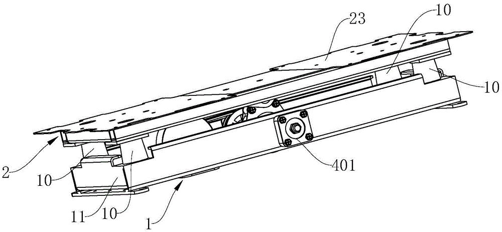
Fig. 1 is a schematic perspective view of a first embodiment of the present invention;
fig. 2 is a schematic view of a bottom perspective structure according to a first embodiment of the present invention;
fig. 3 is a schematic cross-sectional structural view of a first embodiment of the present invention;
fig. 4 is a schematic perspective view of a second embodiment of the present invention;
fig. 5 is an exploded schematic view of the second embodiment of the present invention with the driving mechanism removed;
fig. 6 is a schematic perspective view of a third embodiment of the present invention.
Detailed Description
The present invention will be described in further detail with reference to the following embodiments.
The first embodiment is as follows: as shown in the figure, the vertical rhythm machine for body building comprises a base 1 and a rhythm seat 2 which is vertically and vertically movably arranged on the base 1, wherein a driving mechanism for driving the rhythm seat 2 to vertically move is arranged between the base 1 and the rhythm seat 2, and an elastic supporting mechanism 10 is arranged between the base 1 and the rhythm seat 2.
In this embodiment, the elastic supporting mechanism 10 is an elastic rubber column disposed between the movable seat 2 and the base 1, a lower end of the elastic rubber column is fixedly disposed on an upper end surface of the base 1, and an upper end of the elastic rubber column is fixedly disposed on a lower end surface of the movable seat 2. The elastic rubber column is adopted as the elastic supporting mechanism 10, is stable in supporting, has the characteristic of capability of being reset after being stressed and being capable of being stretched and unloaded, is simple in structure, can realize stable supporting, stretching and resetting, and is low in use cost.
In this embodiment, the elastic rubber column is a circular truncated cone-shaped cylinder structure with a small top and a large bottom, the upper end surface and the lower end surface of the elastic rubber column are both flat end surfaces, the upper end surface of the elastic rubber column is fixedly arranged on the lower end surface of the movable base 2, and the lower end surface of the elastic rubber column is fixedly arranged on the upper end surface of the base 1. The round table-shaped column structure with a small upper part and a big lower part can provide stable support.
In this embodiment, the base 1 includes a square supporting frame 11, the rhythm seat 2 includes a square supporting frame 21 matched with the supporting frame 11, and an elastic supporting mechanism 10 is disposed between each supporting frame 11 and four corners of the supporting frame 21. The base 1 and the rhythm seat 2 are simple in structure and low in cost, and the elastic supporting mechanisms 10 are arranged on the four corners, so that the support is more stable.
In this embodiment, the supporting frame 21 is formed by connecting four square pipes 201 end to end, the lower end faces of four corners of the supporting frame 21 are respectively provided with a horizontal installation backing plate 22, the upper end of the elastic supporting mechanism 10 is fixedly connected with the installation backing plate 22, and the supporting frame 21 is provided with a horizontal rhythm plate 23. The support frame 21 has a simple structure, and the mounting base plate 22 is used for mounting the elastic support mechanism 10.
In this embodiment, a rotating shaft 4 is rotatably connected in the supporting frame 11 from front to back in a penetrating manner, an eccentric wheel 41 is fixedly arranged on the rotating shaft 4, a pushing seat 5 is arranged below the swinging plate 23, a pin shaft 51 is horizontally connected in a penetrating manner from front to back on the pushing seat 5, the central axis of the pin shaft 51 is parallel to the central axis of the rotating shaft 4 and is positioned in the same vertical plane, the pin shaft 51 is connected with the eccentric wheel 41 through a pull rod 6, and the pin shaft 51 and the eccentric wheel 41 are respectively and rotatably arranged in two ends of the pull rod 6;
the driving mechanism comprises a large belt pulley 7, a small belt pulley 8 and a driving motor 9, a main body 91 of the driving motor 9 is fixedly arranged in the supporting frame 11, the large belt pulley 7 is coaxially and fixedly arranged on the rotating shaft 4, the small belt pulley 8 is fixedly arranged on an output shaft (not shown) of the driving motor 9, the central axis of the output shaft of the driving motor 9 is parallel to the central axis of the rotating shaft 4, and the large belt pulley 7 is connected with the small belt pulley 8 through a belt 78. The driving mechanism has a simple structure, and the large belt 78 wheel 7 and the small belt 78 wheel 8 are matched to realize speed reduction, so that the integral stable operation is ensured; the output shaft of the driving motor 9 rotates to drive the small belt pulley 8 to rotate, the large belt pulley 7 connected with the small belt pulley 8 through a belt rotates to drive the rotating shaft 4 to rotate, so that the eccentric wheel 41 on the rotating shaft 4 is driven to rotate, the eccentric wheel 41 rotates to drive the pull rod 6 to vertically move up and down, the pushing seat 5 is driven to vertically move up and down, and the law plate 23 vertically moves up and down under the driving of the pushing seat 5, so that the structure is simple.
In this embodiment, bearing blocks 401 are respectively installed at both ends of the rotating shaft 4, and the bearing blocks 401 are fixedly installed on the supporting frame 11. The rotary connection of the rotating shaft 4 is realized through the two bearing seats 401, and the structure is simple and stable.
In this embodiment, the pushing base 5 includes a horizontal positioning plate 501 fixedly disposed on the lower end surface of the law plate 23, the front end and the rear end of the positioning plate 501 are respectively bent downward vertically to form mounting plates 502, and the pin 51 is fixedly disposed between the two mounting plates 502. The pushing seat 5 is simple in structure and convenient to manufacture, the two mounting plates 502 are used for mounting the pin shaft 51, and the positioning plate 501 is used for mounting the whole pushing seat 5.
Example two: the other parts are the same as the first embodiment, and the difference is that the longitudinal section of the elastic rubber column is hexagonal, the upper end face and the lower end face of the elastic rubber column are both flat end faces, the upper end face of the elastic rubber column is fixedly arranged on the lower end face of the discipline base 2, the lower end face of the elastic rubber column is fixedly arranged on the upper end face of the base 1, and the elastic rubber column is provided with a release hole 101 which is through from front to back. The elastic rubber column with the hexagonal section has better stretching and resetting effects on the basis of realizing stable support.
Example three: the other parts are the same as the first embodiment, except that the elastic support mechanism 10 is a support spring vertically arranged between the rhythm seat 2 and the base 1, the lower end of the support spring is fixedly arranged on the upper end surface of the base 1, and the upper end of the support spring is fixedly arranged on the lower end surface of the rhythm seat 2. The spring is used as the elastic supporting mechanism 10, so that the supporting, stretching and resetting are stable, the structure is simple, and the cost is low.