Tea leaf withering trough
Technical Field
The utility model relates to a technical field, concretely relates to tealeaves withering trough are drawed in separation of natural product active ingredient.
Background
Withering and making withered and withered tea is the name of the tea making process. Spreading the picked fresh leaves according to a certain thickness, and drying in the sun to make the fresh leaves show wilting state. During withering, fresh leaves undergo a series of changes: the moisture is reduced, and the leaves are changed from crisp and hard to soft, so that the leaves are convenient to knead into strips; the activity of enzyme substances contained in the leaves is enhanced, fresh leaf components such as starch, protein, insoluble protopectin, etc. are promoted to be decomposed and converted, effective substances such as glucose, amino acid, soluble pectin, etc. beneficial to the quality of finished tea are generated, and polyphenols are also oxidized to different degrees. Normally and effectively withers to eliminate the grass smell of the fresh leaves to generate faint scent, and the tea has fruity or flowery scent and is mellow in taste but not bitter. Proper conditions of temperature, humidity and air circulation are required for withering. The traditional withering method comprises sunlight withering (solarization), indoor natural withering (spreading and drying) and compound withering which is combined with the two methods, the existing withering equipment needs to be paved manually during feeding, and manual material turning is needed after withering for a period of time, so that the use is inconvenient and the working efficiency is low.
SUMMERY OF THE UTILITY MODEL
An object of the utility model is to provide a tealeaves withering trough solves current equipment of withering and uses inconvenient and lead to the lower problem of work efficiency.
In order to solve the technical problem, the utility model adopts the following technical scheme:
a tea leaf withering trough comprises a trough body, a carrying plate and a material guide mechanism, wherein the trough body is of a rectangular hollow cavity structure with an opening at the upper part, and an electric heating plate and the carrying plate are arranged inside the trough body; the upper part of the groove body is provided with a screw rod through a bearing seat, the upper part of the screw rod is provided with a guide mechanism, the guide mechanism comprises a base, a telescopic rod, a workbench, a feeding hopper, a vibration motor and a disturbance frame, the upper part of the base is connected with the workbench through the telescopic rod, the workbench is provided with a rectangular table, the rectangular table is fixedly provided with the feeding hopper, and the lower part of the feeding hopper is provided with a guide chute; the lower part of the workbench is provided with a fixing lug, and the middle part of the fixing lug is provided with a disturbance frame.
Furthermore, a pressure spring is arranged outside the telescopic rod, a vibration motor is arranged on the upper portion of the base, and the vibration motor is connected with the bottom of the workbench.
Furthermore, the disturbance frame is a roller with a plurality of poke rods, and one end of the disturbance frame is connected with the first driving motor.
Further, a discharge port is arranged at the bottom of the feed hopper, and the discharge port and the guide chute are arranged in an inclined angle of 20-30 degrees.
Further, a carrying sheet is arranged at one end of the groove body, a driving box is arranged on the carrying sheet, a first synchronous wheel connected with the screw port is arranged in the driving box, and the first synchronous wheel is connected with a second synchronous wheel on another screw rod through a synchronous belt.
Furthermore, the first synchronizing wheel, the second synchronizing wheel and the second driving motor are in triangular connection.
Further, the lateral part of the groove body is provided with a fixing strip, the lower part of the fixing strip is provided with a plurality of support legs (3), and at least four support legs are arranged.
Compared with the prior art, the utility model discloses following beneficial effect has:
1. the inside independent electric heating board that is provided with of cell body can cooperate the year thing board on upper portion to dry and wither, and cell body upper portion is provided with the lead screw, and guide mechanism can move on the upper portion of guessing the question under the drive of drive case to carry out the vibration unloading through inside vibrating motor, realize the material tiling and carry the roller bearing efficiency of thing board on, improve equipment.
2. The lower part of the workbench is provided with the fixing lug, the fixing lug is provided with the disturbance roller connected with the first driving motor, and the material can be disturbed and turned around under the matching of the driving box, so that the automatic material turning is realized, and the working efficiency is effectively improved.
Description of the drawings:
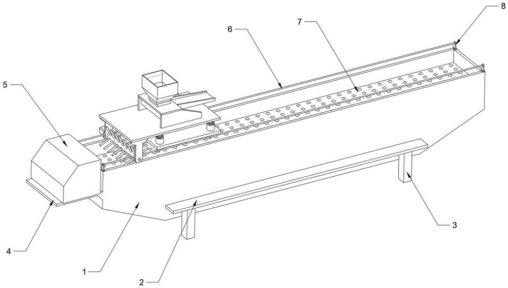
fig. 1 is a schematic structural diagram of the present invention.
Fig. 2 is a schematic view of the internal structure of the tank body of the present invention.
Fig. 3 is a schematic view of a part of the structure of the material guiding mechanism of the present invention.
Fig. 4 is a schematic view of a part of the structure of the driving box of the present invention.
In the figure: 1-groove body, 2-fixed strip, 3-support leg, 4-objective sheet, 5-driving box, 6-screw rod, 7-objective plate, 8-bearing seat, 9-electric heating plate, 10-workbench, 11-fixed lug, 12-disturbance frame, 13-first driving motor, 14-base, 15-telescopic rod, 16-pressure spring, 17-rectangular table, 18-feed hopper, 19-guide groove, 20-vibration motor, 21-first synchronous wheel, 22-synchronous belt and 23-second driving motor.
The specific implementation mode is as follows:
example 1:
fig. 1-4 show a tea withering trough, which comprises a trough body 1, a carrying plate 7 and a material guiding mechanism, wherein the trough body 1 is a rectangular hollow cavity structure with an upper opening, and an electric heating plate 9 and the carrying plate 7 are arranged inside the trough body 1; the upper part of the tank body 1 is provided with a screw rod 6 through a bearing seat 8, the upper part of the screw rod 6 is provided with a material guiding mechanism, the material guiding mechanism comprises a base 14, an expansion link 15, a workbench 10, a feeding hopper 18, a vibration motor 20 and a disturbance frame 12, the upper part of the base 14 is connected with the workbench 10 through the expansion link 15, the workbench 10 is provided with a rectangular table 17, the feeding hopper 18 is fixedly arranged on the rectangular table 17, and the lower part of the feeding hopper 18 is provided with a material guiding groove 19; a fixed lug 11 is arranged at the lower part of the workbench 10, and a disturbance frame 12 is arranged in the middle of the fixed lug 11; among the above-mentioned scheme, 1 inside independent electric heating board 9 that is provided with of cell body can cooperate the year thing board 7 on upper portion to dry and wither, and 1 upper portion of cell body is provided with lead screw 6, and guide mechanism can move on the upper portion of guessing the question under the drive of drive box 5 to carry out vibration unloading through inside vibrating motor 20, realize the material tiling and carry the roller bearing efficiency of thing board 7 on, improve equipment.
Example 2:
in this embodiment, the telescopic rod 15 is further described on the basis of the existing embodiment 1, a pressure spring 16 is disposed outside the telescopic rod 15, a vibration motor 20 is disposed on the upper portion of the base 14, and the vibration motor 20 is connected to the bottom of the worktable 10; the vibration motor 20 can cooperate with the telescopic rod to realize the vibration of the worktable 10, so that the feeding hopper 18 can conveniently feed tea leaves, and the tea leaves are fed into the object carrying plate 7 through the material guide groove 19.
Example 3:
in this embodiment, a disturbance frame 12 is further described on the basis of the existing embodiment 1, where the disturbance frame 12 is a roller with a plurality of poke rods, and one end of the disturbance frame 12 is connected to a first driving motor 13; the lower portion of the workbench is provided with the fixing lugs 11, the disturbance frame 12 connected with the first driving motor 13 is arranged on the fixing lugs 11, and the material can be disturbed and turned back and forth under the cooperation of the driving box 5, so that automatic material turning is achieved, and the working efficiency is effectively improved.
Example 4:
in this embodiment, the feeding hopper 18 is further described on the basis of the prior embodiment 1, in which the bottom of the feeding hopper 18 is provided with a discharge port, and the discharge port and the material guiding chute 19 are arranged at an inclined angle of 25 °; the bottom of the feed hopper 18 is arranged at an inclined angle with the inclined surface of the material guide groove 19, so that the material can be prevented from being discharged too fast, the rectangular cavity structure with an opening at the upper part of the material guide groove 19 is designed to be inclined, and the vibration discharging is facilitated.
Example 5:
in this embodiment, a trough body 1 is further described on the basis of the existing embodiment 1, wherein one end of the trough body 1 is provided with an object carrying sheet 4, a driving box 5 is arranged on the object carrying sheet 4, a first synchronizing wheel 21 connected with a port of a screw rod 6 is arranged in the driving box 5, and the first synchronizing wheel 21 is connected with a second synchronizing wheel on another screw rod through a synchronizing belt 22; the first synchronous wheel 21, the second synchronous wheel and the second driving motor 23 are in triangular connection; the first synchronous wheel 21 and the second synchronous wheel are connected with the screw rod 6 through a coupler and driven by a synchronous belt 22 and a second driving motor 23 to further drive the material guide mechanism to move; the nut is arranged at the bottom of the base 14 of the material guide mechanism and is connected with the screw rod 6, driving is facilitated, the screw rod 6 adopts a reciprocating screw rod, and reciprocating motion can be achieved under unidirectional motion of convenience.
Example 6:
the present embodiment further describes the tank body 1 on the basis of the existing embodiment 1, wherein the side portion of the tank body 1 is provided with a fixing strip 2, the lower portion of the fixing strip 2 is provided with a plurality of support legs 3, and at least four support legs 3 are provided.
Reference throughout this specification to "one embodiment," "another embodiment," "an embodiment," "a preferred embodiment," or the like, means that a particular feature, structure, or characteristic described in connection with the embodiment is included in at least one embodiment described generally in this application. The appearances of the same phrase in various places in the specification are not necessarily all referring to the same embodiment. Further, when a particular feature, structure, or characteristic is described in connection with any embodiment, it is submitted that it is within the scope of the invention to effect such feature, structure, or characteristic in connection with other embodiments.
Although the invention has been described herein with reference to a number of illustrative embodiments thereof, it should be understood that numerous other modifications and embodiments can be devised by those skilled in the art that will fall within the spirit and scope of the principles of this invention. More specifically, various variations and modifications are possible in the component parts and/or arrangements of the subject combination arrangement within the scope of the disclosure, the drawings and the appended claims. In addition to variations and modifications in the component parts and/or arrangements, other uses will also be apparent to those skilled in the art.