Cleaner for medical care
Technical Field
The utility model relates to a medical care equipment technical field especially relates to a cleaner for medical care.
Background
Currently, medical instruments are increasingly frequently reused as their cost increases. While reusing medical instruments, the problem of cross infection of bacteria and viruses is brought, so that the cleaning and disinfection of the medical instruments are more and more paid more attention by medical staff. For medical instruments, the traditional cleaning method is manual cleaning, which is not only low in efficiency, but also difficult to really clean the medical instruments, such as medical instruments with deep holes, blind holes or grooves, by manual cleaning. The existing medical care instrument disinfection and sterilization treatment mode has cleaning dead angles, for example, the medical instruments cannot be thoroughly cleaned due to mutual blocking among the medical instruments, so that the actual requirements cannot be met. Therefore, a new medical nursing cleaner is needed to solve the above technical deficiencies.
For example, chinese patent publication No. CN210253306U discloses a medical care cleaner, which comprises a cleaner body, a bottom plate is disposed at one side in the cleaner body, a push rod motor is disposed at one side of the bottom plate, a push rod loop bar is disposed at one side of the push rod motor, an electric push rod is connected to an output end of the push rod loop bar, a support frame is disposed at one side of the push rod motor, the other end of the electric push rod passes through the support frame, a first limit block is sleeved on one side of the electric push rod, a second limit block is sleeved on the other side of the electric push rod, a containing box is disposed on the support frame, the containing box and the bottom of the support frame are both hollow, a filter screen is disposed at the bottom of the containing box, water pipes are disposed at the upper and lower sides of the containing box, a booster pump is mounted on the water pipes, the shower nozzle is a plurality of. The utility model discloses a following beneficial effect has: the utility model relates to a rationally, collect and wash, dry, disinfect as an organic whole, full automation need not a large amount of labours, washs thoroughly, does not have the dead angle, has fine popularization effect. However, the utility model still has technical shortcomings: as the spray head can only clean the medical instruments from the upper and lower fixed directions, under the condition that the medical instruments are blocked mutually, the spray head is likely to have cleaning dead corners and cannot clean the medical instruments comprehensively.
SUMMERY OF THE UTILITY MODEL
An object of the utility model is to provide a cleaner for medical care, this cleaner for medical care can solve when current cleaner for medical care washs medical instrument because the mutual blocking between the medical instrument and the technique that exists the washing dead angle is not enough.
To achieve the purpose, the utility model adopts the following technical proposal: a medical nursing cleaner at least comprises a cleaner body with a cavity inside. One side in the cleaner body is a cleaning area. At least one placing table for placing medical instruments is detachably connected with the side wall in the cleaning area. At least one large spraying arm driven by a first motor to rotate is rotatably connected in the cleaning area through a first connecting pipe. At least one end of the big spray arm is provided with a small spray arm which is driven by a second motor to rotate. At least one end of the small spray arm is provided with a plurality of spray heads. Under the condition that the spray header on the small spray arm can spray water flow, the small spray arm is rotatably connected with one end of the large spray arm through a second connecting pipe in a mode that the water flow sprayed by the spray header comprehensively washes the medical instrument on the placing table at a constantly changing washing angle under the action of centrifugal force when the small spray arm rotates through the rotation of the large spray arm.
According to a preferred embodiment, the second connection pipe is detachably connected with a booster pump in such a manner that a high pressure water source can be provided for the large spray arm and the small spray arm.
According to a preferred embodiment, the placing table is provided with a containing box for placing medical instruments. The containing box is set to be a net structure according to the mode that the spray head can conveniently spray water flow to wash medical instruments.
According to a preferred embodiment, a plurality of grills are detachably connected to the containing box in a manner that medical instruments in the containing box can be orderly placed to reduce mutual blocking among the medical instruments.
According to a preferred embodiment, the other side inside the cleaner body is a drying and sterilizing zone. And a conveyor belt is arranged in the drying and sterilizing area in a manner that the storage box can be conveyed to the drying and sterilizing area. The conveyor belt is detachably connected to the third motor by a drive wheel in such a way that it can be driven by the third motor.
According to a preferred embodiment, the side walls of the cleaning zone are provided with electric pushers in such a way as to be able to push the containers from the placing table to the conveyor belt.
According to a preferred embodiment, a blower is detachably attached to the outside of the cleaner body. One side of the blower is connected to one end of the ventilation pipeline. The other end of the ventilation pipeline is communicated to the drying and sterilizing area in a mode that medical instruments in the drying and sterilizing area can be dried through the blower.
According to a preferred embodiment, a link is detachably connected to one side in the dry sterilizing zone. The connecting rod is provided with a disinfection lamp according to a mode of disinfecting medical instruments in the drying and disinfecting area.
According to a preferred embodiment, the cleaning zone is provided with a drain in such a way that the waste liquid in the cleaning zone can be drained.
According to a preferred embodiment, a partition is arranged between the cleaning zone and the drying and sterilizing zone in such a way as to prevent the water flow in the cleaning zone from spraying into the drying and sterilizing zone. A movable plate is hinged to the partition plate in a mode that the electric push rod can push the containing box to the conveying belt conveniently.
The utility model discloses a beneficial technological effect includes at least:
the utility model has the advantages that the cleaner body is internally provided with the large spray arm driven by the first motor to rotate and the small spray arm driven by the second motor to rotate, and then the small spray arm is driven by the rotation of the large spray arm to rotate, so that the density of water flow jetted from the spray head of the small spray arm is greatly increased by the configuration mode; in addition, the water flow jetted from the spray header of the small spray arm can change direction constantly under the action of centrifugal force, for example, different jet water flows in horizontal, vertical and inclined directions are formed; finally, the water flow sprayed from the spray header of the small spray arm can wash the medical instruments at a constantly changing washing angle, so that the mutual blocking among the medical instruments is avoided, and the medical instruments in the cleaning area can be washed comprehensively without dead angles.
Drawings
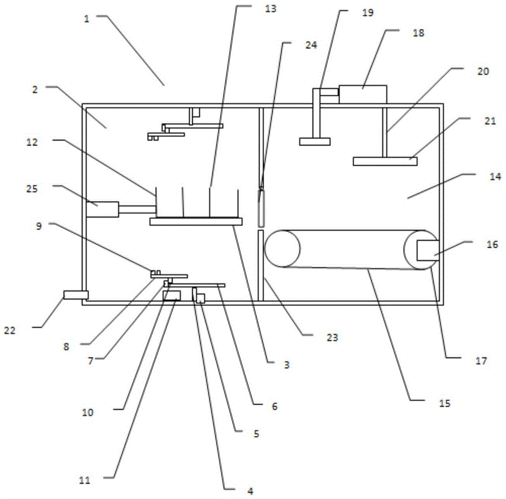
FIG. 1 is a simplified schematic diagram of a preferred embodiment of the present invention;
FIG. 2 is a simplified schematic diagram of a preferred embodiment of the large and small spray arms of the present invention;
figure 3 is a simplified schematic diagram of a preferred embodiment of the small spray arm and showerhead of the present invention.
List of reference numerals
1: a cleaner body 2: cleaning zone 3: placing table
4: first connecting pipe 5: first motor 6: big spray arm
7: second motor 8: the small spray arm 9: spray head
10: second connection pipe 11: 12, a booster pump: storage box
13: grid 14: drying and sterilizing area 15: conveyor belt
16: third motor 17: the transmission wheel 18: blower fan
19: ventilation duct 20: the connecting rod 21: disinfection lamp
22: the drain pipe 23: separator 24: movable plate
25: electric push rod
Detailed Description
The following detailed description is made with reference to the accompanying drawings.
As shown in fig. 1 and 2, a medical care cleaner includes at least a cleaner body 1 having a cavity therein. One side inside the cleaner body 1 is a cleaning zone 2. At least one placing table 3 for placing medical instruments is detachably connected to the side wall in the cleaning area 2. At least one large spray arm 6, which is driven by a first electric motor 5 to rotate, is rotatably connected in the cleaning region 2 via a first connecting pipe 4. At least one end of the large spray arm 6 is provided with a small spray arm 8 which is driven by a second motor 7 to rotate. As shown in fig. 3, at least one end of the small shower arm 8 is provided with a plurality of shower heads 9. Under the condition that the spray header 9 on the small spray arm 8 can spray water flow, the small spray arm 8 is rotatably connected with one end of the large spray arm 6 through the second connecting pipe 10 in a manner that the water flow sprayed by the spray header 9 washes the medical instrument on the placing table 3 comprehensively at a constantly changing washing angle under the action of centrifugal force when the small spray arm 8 is rotated through the rotation of the large spray arm 6. Preferably, the cleaner body 1 may have a rectangular parallelepiped shape or a square shape. Preferably, the standing board 3 may have a rectangular parallelepiped shape. Preferably, the standing board 3 may have a net structure. The placement stage 3 thus configured can facilitate the water jet ejected from the shower arm 8 to be ejected through the placement stage 3 onto the medical instrument to be cleaned. Preferably, the interior of the large spray arm 6 can be provided with a line for conveying cleaning liquid and/or fresh water. Preferably, the number of large spray arms 6 may be two. Preferably, two large spray arms 6 may be detachably connected to the top and bottom of the cleaner body 1 through the first connection pipe 4, respectively. Preferably, the first connection pipe 4 may be a general metal pipe. Preferably, one end of the first connection tube 4 may also be rotatably connected to the sidewall of the cleaning zone 2 by a rotation shaft. Preferably, the other end of the first connection pipe 4 may be rotatably connected to the middle of the large spray arm 6 by a rotation shaft. Preferably, one end of the second connection pipe 10 may be rotatably connected to a side surface of the large spray arm 6 away from the inner wall of the cleaning zone 2 by a rotation shaft. Preferably, the other end of the second connection pipe 10 may be rotatably connected to the middle portion of the small spray arm 8 by a rotation shaft. Preferably, the interior of the small spray arm 8 can be provided with a line for conveying cleaning liquid and/or fresh water. Preferably, one end of the small spray arm 8 may be provided with six spray headers 9. Preferably, the surface of the small spray arm 8 on the side where the spray header 9 is located may be in a circular arc shape. The small spray arms 8 are configured so that the spray headers 9 on the small spray arms 8 can spray in a number of different directions when both the large spray arm 6 and the small spray arm 8 are stationary. Preferably, the length of the small spray arm 8 may be half the length of the large spray arm 6. Preferably, the length of the large spray arm 6 can be flexibly set according to actual requirements. Preferably, a plurality of spray headers 9 may also be provided on the large spray arm 6. Preferably, the large spray arm 6 can be rotated by the first motor 5 directly through a gear. Preferably, the large spray arm 6 may also be driven in rotation indirectly by a belt powered by the first motor 5. With this arrangement, the small spray arms 8 can be rotated by the rotation of the large spray arms 6, so that the density of the water streams ejected from the spray heads 9 of the small spray arms 8 can be greatly increased. At the same time, the water jet from the shower head 9 of the small shower arm 8 can be constantly redirected by centrifugal force, for example, to form different water jets in horizontal, vertical, and inclined directions. Finally, the water flow sprayed from the spray header 9 of the small spray arm 8 can wash the medical instruments at a constantly changing washing angle, so that the mutual blocking among the medical instruments is avoided, and the medical instruments in the cleaning area 2 can be washed comprehensively without dead angles.
According to a preferred embodiment, a booster pump 11 is detachably connected to the second connection pipe 10 in such a manner as to be able to provide a high-pressure water source for the large and small shower arms 6 and 8. Preferably, the booster pump 11 may be disposed at the bottom of the cleaning zone 2. With this arrangement, the booster pump 11 can boost the cleaning liquid and/or fresh water from outside the cleaner and deliver it to the conduit in the large spray arm 6 via the second connecting pipe 10 and then to the spray header 9 on the small spray arm 8 via the first connecting pipe 4.
According to a preferred embodiment, the placing table 3 is provided with a storage box 12 for placing medical instruments. The storage box 12 is provided with a net structure according to a mode that the spray head 9 can conveniently spray water to wash the medical instruments. Preferably, the storage box 12 may have a square shape or a cylindrical shape. Preferably, the entire storage box 12 may have a net structure. Through the configuration mode, water flow jetted from the small spraying arm 8 can be conveniently jetted into the containing box 12 from all directions, so that mutual blocking among medical instruments is avoided, and finally, the medical instruments in the containing box 12 are thoroughly washed without dead angles.
According to a preferred embodiment, a plurality of grills 13 are detachably connected to the storage box 12 in such a manner that the medical instruments in the storage box 12 can be orderly arranged to reduce mutual interference between the medical instruments. Preferably, the grid 13 may be rectangular. Preferably, the grid 13 may also be provided as a mesh structure. Preferably, the grill 13 may be perpendicular to the bottom surface of the receiving box 12. With this arrangement, the medical instruments in the storage box 12 can be spaced apart from each other by the grill 13, so that a certain gap is left between the medical instruments so that the water flow sprayed from the shower head 9 can wash the corners of the medical instruments in the storage box 12. Preferably, the number of the grids 13 may be three.
According to a preferred embodiment, the other side inside the cleaner body 11 is a dry sterilizing zone 14. A conveyor belt 15 is provided in the drying and sterilizing zone 14 so as to convey the storage box 12 to the drying and sterilizing zone 14. The conveyor belt 15 is detachably connected to the third motor 16 via a drive wheel 17 in such a way that it can be driven by the third motor 16. Preferably, one end of the conveyor belt 15 may open into the placing table 3. Preferably, the other end of the conveyor belt 15 may be led out of the cleaner body 1. Preferably, the third motor 16 may be detachably coupled to a sidewall of the dry sterilizing zone 14. Preferably, the conveyor belt 15 may be at the same level as the placing table 3. Preferably, the number of the rotating wheels may be two. With this configuration, the medical instruments dried and sterilized in the drying and sterilizing zone 14 can be conveyed out of the cleaner body 1 by the conveyor belt 15.
According to a preferred embodiment, the side walls of the cleaning zone 2 are provided with electric pushers 25 in such a way as to be able to push the containers 12 from the placing table 3 to the conveyor belt 15. Preferably, the electric push rod 25 may be a conventional one, such as a model U10 electric push rod manufactured by Temmin technologies, Inc.
According to a preferred embodiment, a blower 18 is detachably attached to the outside of the cleaner body 11. One side of the blower 18 is connected to one end of a ventilation duct 19. The other end of the ventilation duct 19 is communicated to the drying and sterilizing region 14 in such a manner that the medical instruments in the drying and sterilizing region 14 can be dried by the blower 18. Preferably, the blower 18 may be provided on a sidewall surface outside the cleaner body 1.
According to a preferred embodiment, a link 20 is detachably coupled to one side in the dry sterilizing zone 14. The connecting rod 20 is provided with a sterilizing lamp 21 in such a manner as to sterilize the medical instruments in the dry sterilizing zone 14. Preferably, the sterilizing lamp 21 may be an ultraviolet sterilizing lamp.
According to a preferred embodiment, the cleaning zone 2 is provided with a drain 22 in such a way that the waste liquid in the cleaning zone 2 can be drained. Preferably, the drain pipe 22 may be provided at the bottom of the cleaning zone 2.
According to a preferred embodiment, a partition 23 is provided between the clean zone 2 and the dry-sterilizing zone 14 in such a way as to prevent the water flow inside the clean zone 2 from spraying into the dry-sterilizing zone 14. A movable plate 24 is hinged in the partition plate 23 in a manner that the electric push rod 25 can conveniently push the containing box 12 to the conveyor belt 15. Preferably, the partition 23 may have a rectangular parallelepiped shape. Preferably, the height and width of the movable plate 24 may be at least not lower than the height and width of the receiving box 12. Preferably, the number of the partitions 23 may be one. Preferably, the number of the movable plates 24 may be one. Preferably, the movable plate 24 may be square in shape. By the configuration mode, the partition 23 can block the water jet of the cleaning area 2 from entering the drying and sterilizing area 14, and meanwhile, the containing box 12 can conveniently enter the drying and sterilizing area through the movable plate 24.
In order to facilitate understanding of the working principle of the present embodiment, the working process of the present invention is briefly described as follows: first, medical instruments to be cleaned are respectively put into the plurality of grills 13 in the storage box 12 so that a certain gap is left between the medical instruments. Next, the storage box 12 is placed on the placement table 3. After that, the booster pump 11, the first motor 5, and the second motor 7 are turned on. Then, the booster pump 11 will boost the water flow and deliver the boosted water flow to the large spray arm 6 and the small spray arm 8, and the large spray arm 6 is rotated by the first motor 5 to rotate the small spray arm 8. At the same time, the small shower arm 8 can also rotate itself under the drive of the second motor 7. Therefore, the configuration can greatly increase the density of the water flow sprayed from the spray header 9 on one hand; on the other hand, the water jet from the small spray arm 8 may be constantly changed in direction by the centrifugal force, for example, to form a water jet in horizontal, vertical, and inclined directions. Therefore, water flow sprayed by the spray head 9 of the small spray arm 8 can spray water flow to a plurality of different directions in the cleaning area 2 to avoid blocking of part of medical instruments, and then all the medical instruments in the cleaning area 2 are washed comprehensively without dead angles. Then, the waste liquid having cleaned the medical instrument may be discharged to the outside of the cleaner body 1 through the drain pipe 22. Next, the electric pusher 25 may be activated, and the electric pusher 25 may push the storage box 12 onto the conveyor belt 15. After that, the blower 18 may be activated to dry the medical instruments in the storage box 12 on the conveyor belt 15. At the same time, the third motor 16 is started to convey the storage box 12 to the lower side of the sterilizing lamp 21 by the conveyor belt 15, and then the sterilizing lamp 21 is turned on to sterilize and disinfect the medical instruments on the storage box 12. Finally, the medical instrument in the storage box 12 is conveyed out of the cleaner body 1 by the conveyor belt 15.
It should be noted that the above-mentioned embodiments are exemplary, and those skilled in the art can devise various solutions in light of the present disclosure, which are also within the scope of the present disclosure and fall within the scope of the present disclosure. It should be understood by those skilled in the art that the present specification and drawings are illustrative only and are not limiting upon the claims. The scope of the invention is defined by the claims and their equivalents.