Pulse bag-type dust collector for feed processing
Technical Field
The utility model relates to a feed processing technology field, concretely relates to pulse bag dust remover for feed processing.
Background
In the process of feed production and processing, the processes of feeding, crushing, stirring, granulating and the like of raw materials can generate dust, and the dust can not only harm the health of workers, but also possibly cause dust explosion, so that the dust needs to be removed in time in the process of feed production and processing.
The pulse bag dust collector is a common dust collector for feed production and processing, and comprises a dust hopper, a dust collection box body and an upper box body, wherein a filter bag is arranged in the dust collection box body, dust-containing gas enters the dust hopper from an air inlet duct during working, coarse dust particles directly fall into the bottom of the dust hopper, fine dust particles upwards enter the dust collection box body along with the turning of air flow, dust is deposited on the outer surface of the filter bag, and the filtered gas enters the upper box body to a clean gas collecting pipe-an exhaust duct and is exhausted to the atmosphere through an exhaust fan. The ash cleaning process is to cut off the air duct at the clean air outlet of the chamber to make the cloth bag in the state of no air flow passing through (air stopping and ash cleaning in different chambers). Then the pulse valve is opened to carry out pulse injection ash removal by compressed air, the closing time of the stop valve is enough to ensure that dust stripped from the filter bag after injection is settled to the ash bucket, the phenomenon that the dust is attached to the surface of the adjacent filter bag along with airflow after being separated from the surface of the filter bag is avoided, the ash removal of the filter bag is thorough, and the programmable controller carries out full-automatic control on an exhaust valve, the pulse valve, an ash discharge valve and the like.
The filter bag in the dust removal box body needs to be replaced regularly after being used for a period of time, however, the conventional bag-type dust remover has the problem that the filter bag is troublesome to replace.
SUMMERY OF THE UTILITY MODEL
To the defect among the prior art, the utility model provides a pulse bag dust remover for feed processing to change the filter bag.
The utility model provides a pulse bag dust collector for feed processing, including the dust removal box, locate the last box of dust removal box upside and locate the ash bucket of dust removal box downside, the lateral part of dust removal box is equipped with dirt gas inlet, is equipped with the baffle between dust removal box and the last box, is equipped with a plurality of through-holes on the baffle, is equipped with a plurality of and each filter bag subassembly of through-hole one-to-one in the dust removal box, and each filter bag subassembly all includes the filter bag frame and overlaps the dust removal filter bag outside the filter bag frame, the lateral part of upper box is equipped with the net gas outlet, is equipped with the jetting pipe in the upper box, is equipped with a plurality of and each nozzle that filter bag subassembly one-to-one corresponds on the jetting pipe, the bottom of ash bucket is equipped with the dust exhaust; the top of the upper box body is provided with a detachable upper cover plate; the outer edge of the upper end of each filter bag frame is provided with a supporting baffle ring, one filter bag frame correspondingly penetrates through a through hole in the partition plate, the supporting baffle ring at the upper end of the filter bag frame is supported on the partition plate, and the injection pipe is respectively connected with each supporting baffle ring through a connecting frame.
Furthermore, an annular magnet is sleeved outside each filter bag assembly, two sides of the annular magnet are respectively adsorbed to the supporting baffle ring and the partition plate, and the bag opening of each dust removal filter bag is clamped between the annular magnet and the supporting baffle ring.
Furthermore, the upper end of each filter bag frame is provided with a venturi tube.
Further, the upper cover plate is fixed to the top of the upper box body through bolts.
The electromagnetic pulse device comprises an air bag, a pulse valve and a blowing pipe joint, wherein the pulse valve is connected between the air bag and the blowing pipe joint in series through a pipeline, and the blowing pipe joint is detachably connected with the blowing pipe.
Furthermore, the air bag is fixed on the outer side of the dust removal box body through the support, the injection pipe joint is fixed on the side wall of the dust removal box body, the connecting end of the injection pipe is provided with a convex edge, the convex edge is in butt joint with the injection pipe joint and is fixed through a connecting cover, the connecting cover is provided with a bottom plate and a ring body, the bottom plate is sleeved outside the injection pipe, the ring body is in threaded sleeve connection outside the injection pipe joint, and when the connecting cover is screwed down, the bottom plate enables the convex edge to be abutted against the side end of the injection pipe joint.
Further, the upper side of the dust gas inlet is connected with a baffle plate which inclines downwards.
The dust removal box further comprises supporting legs, and the supporting legs are connected with the dust removal box body and used for supporting and fixing the dust removal box body and the ash bucket on the ground.
Furthermore, the ash discharging device comprises an ash discharging port arranged at the bottom of the ash bucket and an ash discharging valve arranged at the ash discharging port.
The beneficial effects of the utility model are embodied in: this application keeps off the ring through establishing the support in the upper end of filter bag frame, the support keeps off the ring and plays the effect of supporting installation filter bag frame, and, keep off the ring with each support and pass through the link connection on an injection pipe, each filter bag frame combines to form a whole on the injection pipe, when needing to change dust bag, the upper cover plate on the last box is opened, rethread injection pipe is whole with each filter bag frame and is mentioned, the filter bag frame leaves behind the last box, directly change the outer dust bag of filter bag frame, pass the through-hole on the baffle with the filter bag frame again and pack into the dust bag body, cover the upper cover plate at last can, the filter bag is changed conveniently, and is swift.
Drawings
In order to more clearly illustrate the embodiments of the present invention or the technical solutions in the prior art, the drawings used in the embodiments or the technical solutions in the prior art will be briefly described below. Throughout the drawings, like elements or portions are generally identified by like reference numerals. In the drawings, elements or portions are not necessarily drawn to scale.
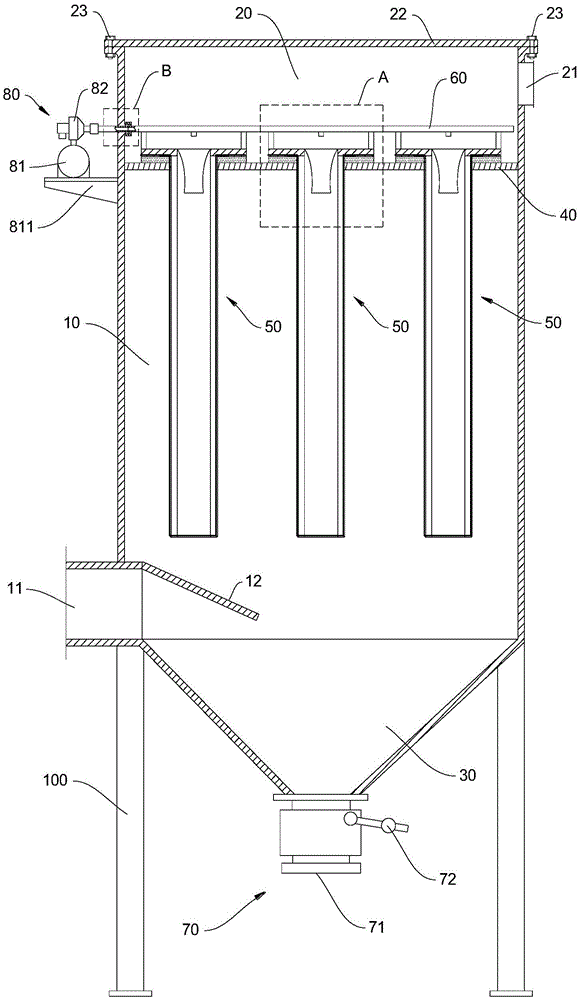
Fig. 1 is a schematic structural diagram of an embodiment of the present invention;
FIG. 2 is an enlarged view of portion A of FIG. 1;
fig. 3 is an enlarged view of a portion B of fig. 1.
In the attached drawings, 10-a dust removal box body; 11-dust gas inlet; 12-a baffle plate; 20-loading the box body; 21-purified gas outlet; 22-upper cover plate; 23-a bolt; 30-ash bucket; 40-a separator; 41-through holes; 50-a filter bag assembly; 51-a filter bag frame; 52-dust removal filter bag; 53-support stop ring; 54-a ring magnet; a 55-venturi; 60-blowing pipe; 61-a nozzle; 62-a connecting frame; 63-convex edge; 70-ash discharge device; 71-an ash discharge port; 72-ash discharge valve; 80-an electromagnetic pulse device; 81-air bag; 811-a scaffold; 82-a pulse valve; 83-a blowing pipe joint; 90-connecting the cover; 91-a base plate; 92-a ring body; 100-support leg.
Detailed Description
Embodiments of the present invention will be described in detail below with reference to the accompanying drawings. The following examples are only for illustrating the technical solutions of the present invention more clearly, and therefore are only examples, and the protection scope of the present invention is not limited thereby.
It is to be noted that unless otherwise specified, technical or scientific terms used herein shall have the ordinary meaning as understood by those skilled in the art to which the present invention belongs.
As shown in fig. 1-3, an embodiment of the present invention provides a pulse bag dust collector for feed processing, which comprises a dust collecting box 10, an upper box 20 disposed on the upper side of the dust collecting box 10, an ash bucket 30 disposed on the lower side of the dust collecting box 10, an electromagnetic pulse device 80, and legs 100.
The legs 100 are connected to the dust-removing case 10 for supporting the dust-removing case 10 and the dust hopper 30 on the ground.
The dust-removing box 10 has a dust inlet 11 at its side, and a downwardly inclined baffle 12 is connected to the upper side of the dust inlet 11 to ensure that coarse dust particles can directly fall into the bottom of the dust hopper 30.
A partition plate 40 is arranged between the dust removing box body 10 and the upper box body 20, a plurality of through holes 41 are arranged on the partition plate 40, a plurality of filter bag assemblies 50 which are in one-to-one correspondence with the through holes 41 are arranged in the dust removing box body 10, and each filter bag assembly 50 comprises a filter bag frame 51 and a dust removing filter bag 52 sleeved outside the filter bag frame 51.
The side part of the upper box body 20 is provided with a clean air outlet 21, the upper box body 20 is internally provided with an injection tube 60, the injection tube 60 is provided with a plurality of nozzles 61 which are in one-to-one correspondence with the filter bag assemblies 50, and during dust cleaning, the nozzles 61 can be supplied with air through the injection tube 60, and dust is cleaned by blowing air to the dust removal filter bags 52. Preferably, each filter bag frame 51 is provided at an upper end thereof with a venturi tube 55, and a nozzle 61 is aligned with one venturi tube 55, so that the effect of blowing and cleaning ash can be improved by providing the venturi tube 55.
The upper case 20 is provided at the top thereof with a detachable upper cover plate 22, and as a specific example, the upper cover plate 22 is fixed to the top of the upper case 20 by bolts 23.
The outer edge of the upper end of each filter bag frame 51 is provided with a supporting stop ring 53, a filter bag frame 51 correspondingly penetrates through a through hole 41 on the partition plate 40, the supporting stop ring 53 at the upper end of the filter bag frame 51 is supported on the partition plate 40, and the injection pipe 60 is respectively connected with each supporting stop ring 53 through a connecting frame 62.
The bottom of the ash bucket 30 is provided with an ash discharging device 70. As a specific example, the ash discharge device 70 includes an ash discharge port 71 provided at the bottom of the ash bucket 30 and an ash discharge valve 72 installed at the ash discharge port 71, and the ash discharge valve 72 is opened when discharging ash.
When the dust removing box works, dust-containing gas enters the dust hopper 30 from the dust gas inlet 11, coarse dust particles directly fall into the bottom of the dust hopper 30, fine dust particles turn upwards along with airflow and enter the dust removing box body 10, dust is deposited on the outer surface of the dust removing filter bag 52, and the filtered gas enters the upper box body 20 and is discharged through the clean gas outlet 21, so that the dust removing effect is achieved.
This application keeps off ring 53 through establishing the support in the upper end of filter bag frame 51, support and keep off ring 53 and play the effect of supporting installation filter bag frame 51, and, keep off ring 53 with each support and connect on a jetting pipe 60 through link 62, each filter bag frame 51 combines to form a whole on jetting pipe 60, when needing to change dust bag 52, upper cover plate 22 on the box 20 is opened, each filter bag frame 51 is whole to be mentioned through jetting pipe 60, filter bag frame 51 leaves last box 20 after, directly change the outer dust bag 52 of filter bag frame 51, pass through-hole 41 on the baffle 40 with filter bag frame 51 again and load into dust box 10, cover upper cover plate 22 at last can, the filter bag is changed conveniently, swiftly.
The electromagnetic pulse device 80 comprises an air bag 81, a pulse valve 82 and an injection blow pipe connector 83, wherein the pulse valve 82 is connected in series between the air bag 81 and the injection blow pipe connector 83 through a pipeline, and the injection blow pipe connector 83 is detachably connected with the injection blow pipe 60. In the ash removal process, the pulse valve 82 is opened, compressed air in the air bag 81 is introduced into the injection pipe 60 and is injected into the dust filter bag 52 through each nozzle 61, and therefore blowing ash removal of the dust filter bag 52 is achieved.
When the dust filter 52 is replaced, the injection tube 60 and the filter frame 51 need to be taken out together, and the injection tube connector 83 and the injection tube 60 need to be disconnected from each other, so that the injection tube connector 83 and the injection tube 60 are detachably connected to each other. As a specific example, referring to fig. 1 and 3, the air bag 81 is fixed to the outside of the dust-removing box 10 by a bracket 811, the blowing pipe joint 83 is fixed to the side wall of the dust-removing box 10, the connecting end of the blowing pipe 60 has a protruding edge 63, the protruding edge 63 abuts against the blowing pipe joint 83 and is fixed by a connecting cover 90, the connecting cover 90 has a bottom plate 91 and a ring body 92, the bottom plate 91 is sleeved outside the blowing pipe 60, the ring body 92 is screwed outside the blowing pipe joint 83, when the connecting cover 90 is screwed, the bottom plate 91 abuts against the protruding edge 63 against the side end of the blowing pipe joint 83, so that the connection between the blowing pipe joint 83 and the blowing pipe 60 can be realized by screwing the connecting cover 90, and the connection between the blowing pipe joint 83 and the blowing pipe 60 can be realized by unscrewing the connecting cover 90, thereby facilitating the installation and removal between the blowing pipe joint 83 and the blowing pipe 60.
As a preferred embodiment, referring to fig. 2, each filter bag assembly 50 is further sleeved with a ring-shaped magnet 54, two sides of the ring-shaped magnet 54 are respectively attached to the supporting baffle ring 53 and the partition plate 40, and the mouth of the filter bag 52 is clamped between the ring-shaped magnet 54 and the supporting baffle ring 53, so that not only can the mouth of the filter bag 52 be fixed, but also the supporting baffle ring 53 can be attached and fixed to the partition plate 40, thereby improving the stability of the installation of the filter bag assembly 50.
Finally, it should be noted that: the above embodiments are only used to illustrate the technical solution of the present invention, and not to limit the same; although the present invention has been described in detail with reference to the foregoing embodiments, it should be understood by those skilled in the art that: the technical solutions described in the foregoing embodiments may still be modified, or some or all of the technical features may be equivalently replaced; such modifications and substitutions do not substantially depart from the scope of the embodiments of the present invention, and are intended to be covered by the claims and the specification.