CN213533703U - Cable sheath pipe extrusion moulding equipment - Google Patents
Cable sheath pipe extrusion moulding equipment Download PDFInfo
- Publication number
- CN213533703U CN213533703U CN202022588996.6U CN202022588996U CN213533703U CN 213533703 U CN213533703 U CN 213533703U CN 202022588996 U CN202022588996 U CN 202022588996U CN 213533703 U CN213533703 U CN 213533703U
- Authority
- CN
- China
- Prior art keywords
- fixedly connected
- water
- wall
- pipe
- driving motor
- Prior art date
- Legal status (The legal status is an assumption and is not a legal conclusion. Google has not performed a legal analysis and makes no representation as to the accuracy of the status listed.)
- Expired - Fee Related
Links
- 238000001125 extrusion Methods 0.000 title claims abstract description 26
- 238000003756 stirring Methods 0.000 claims abstract description 13
- 238000010438 heat treatment Methods 0.000 claims abstract description 10
- XLYOFNOQVPJJNP-UHFFFAOYSA-N water Substances O XLYOFNOQVPJJNP-UHFFFAOYSA-N 0.000 claims description 123
- 238000001816 cooling Methods 0.000 claims description 16
- 238000009413 insulation Methods 0.000 claims description 2
- 239000002994 raw material Substances 0.000 abstract description 9
- 238000004519 manufacturing process Methods 0.000 abstract description 8
- 238000004321 preservation Methods 0.000 abstract description 8
- 230000000903 blocking effect Effects 0.000 abstract description 3
- 230000000694 effects Effects 0.000 abstract description 3
- 239000000463 material Substances 0.000 description 19
- 230000007246 mechanism Effects 0.000 description 3
- 238000002844 melting Methods 0.000 description 2
- 230000008018 melting Effects 0.000 description 2
- 238000000034 method Methods 0.000 description 2
- 230000008569 process Effects 0.000 description 2
- 239000002699 waste material Substances 0.000 description 2
- 238000010521 absorption reaction Methods 0.000 description 1
- 230000009471 action Effects 0.000 description 1
- 230000006978 adaptation Effects 0.000 description 1
- 230000004075 alteration Effects 0.000 description 1
- 230000009286 beneficial effect Effects 0.000 description 1
- 239000002131 composite material Substances 0.000 description 1
- 230000007547 defect Effects 0.000 description 1
- 230000017525 heat dissipation Effects 0.000 description 1
- 230000008676 import Effects 0.000 description 1
- 239000000155 melt Substances 0.000 description 1
- 239000000289 melt material Substances 0.000 description 1
- 238000012986 modification Methods 0.000 description 1
- 230000004048 modification Effects 0.000 description 1
- 238000004806 packaging method and process Methods 0.000 description 1
- 238000010094 polymer processing Methods 0.000 description 1
- 238000007711 solidification Methods 0.000 description 1
- 230000008023 solidification Effects 0.000 description 1
- 230000006641 stabilisation Effects 0.000 description 1
- 238000011105 stabilization Methods 0.000 description 1
- 238000006467 substitution reaction Methods 0.000 description 1
- 239000002918 waste heat Substances 0.000 description 1
Images
Landscapes
- Extrusion Moulding Of Plastics Or The Like (AREA)
Abstract
The utility model discloses a cable sheathing pipe extrusion moulding equipment, which comprises a tank body, the top of the jar body is provided with driving motor No. one, driving motor's output shaft extends to the inside and the fixedly connected with puddler of the jar body, the outer wall fixedly connected with stirring leaf of puddler, the top of the jar body is provided with the feeder hopper, the lateral wall of the jar body is provided with driving motor No. two, driving motor's output shaft extends to the inside and the fixedly connected with pivot of the jar body No. two, the outer wall fixedly connected with spiral leaf of pivot, the inner wall fixedly connected with heating tube of the jar body, the lateral wall of the jar body is provided with the bush, the bush is through being provided with connecting piece fixedly connected with mandrel. Through the heat preservation that sets up, the heat preservation plays heat retaining effect to the internal stability of jar, prevents thermal giving off and extravagant, has avoided the raw materials can not fully melt and cause feed cylinder blocking phenomenon, makes the raw materials flow unsmoothly, has improved production quality, has reduced manufacturing cost.
Description
Technical Field
The utility model belongs to the technical field of the sheath production facility, concretely relates to cable sheathing pipe extrusion moulding equipment.
Background
Extrusion molding is also called extrusion molding in plastic processing, and means that materials are heated and plasticized while being pushed forward by a screw under the action of a charging barrel and the screw of an extruder, and the extrusion molding is mainly used for producing continuous profiles with certain cross sections, such as thin cables, films, sheets, plates, hard tubes, hoses, corrugated tubes, profiles, wires, packaging tapes, rods, nets, composite films and the like; extrusion molding has been widely used in polymer processing; however, when the existing cable outer sheath is subjected to extrusion molding, the raw materials are likely to be solidified due to heat dissipation in the conveying process, the solidification of the raw materials can cause the phenomenon that the raw materials cannot be sufficiently melted in the extrusion molding process to cause the blockage of the charging barrel, the extrusion molding quality of a product is influenced, the raw materials cannot flow smoothly, and the working efficiency is reduced.
The Chinese patent CN207630478U7 discloses a power cable sheath pipe extrusion molding device, which can fully melt materials, prevent blockage in the production process and greatly improve the production efficiency, but has certain defects that firstly, a spiral water pipe is adopted for cooling a sheath layer cooling mechanism, the whole cooling channel is discontinuous, the temperature is not uniform around, so that after an extruded insulating layer is contacted with the cooling channel, the surface of the extruded insulating layer is corrugated due to the temperature difference, and the cable quality is influenced; secondly, no heat preservation mechanism is arranged outside the heating pipeline, so that waste of heat energy resources is caused, and the processing cost is increased.
SUMMERY OF THE UTILITY MODEL
An object of the utility model is to provide a cable sheathing pipe extrusion moulding equipment, put forward current a power cable sheathing pipe extrusion moulding device in solving above-mentioned background art in the use, owing to adopt spiral water pipe cooling, whole cooling channel is discontinuous, uneven and the outside of heat pipe does not set up the heat preservation mechanism around the temperature, thereby lead to extruding insulating layer and cooling channel contact back, it has the ripple to lead to extruding the insulating layer surface because the existence of the difference in temperature, influence the waste of cable quality and heat energy resource, the increase problem of processing cost.
In order to achieve the above object, the utility model provides a following technical scheme: cable sheath pipe extrusion moulding equipment, which comprises a tank body, the top of the jar body is provided with driving motor No. one, driving motor's output shaft extends to the inside and the fixedly connected with puddler of the jar body, the outer wall fixedly connected with stirring leaf of puddler, the top of the jar body is provided with the feeder hopper, the lateral wall of the jar body is provided with driving motor No. two, driving motor's output shaft extends to the inside and the fixedly connected with pivot of the jar body, the outer wall fixedly connected with spiral leaf of pivot, the inner wall fixedly connected with heating tube way of the jar body, the lateral wall of the jar body is provided with the bush, the bush is through being provided with connecting piece fixedly connected with mandrel.
Preferably, the outer wall of bush has cup jointed the cold water pipe, the top outer wall of cold water pipe is provided with the mouth of pipe of intaking, the bottom outer wall of cold water pipe is provided with the mouth of pipe of intaking, the outer wall fixedly connected with water inlet hose of the mouth of pipe of intaking, the water inlet hose is kept away from the water pump of the one end fixedly connected with of the mouth of pipe of intaking, the water tank of the lateral wall fixedly connected with of a water pump, the outer wall fixedly connected with of the mouth of pipe of intaking goes out the water hose, go out the water hose keep away from the water tank of No. two water tanks of the one end fixedly connected with of the mouth of pipe of intaking, the lateral wall of No. two water tanks is provided with the water pump No. two, the output shaft fixedly connected.
Preferably, the tank body comprises a shell, and the inner wall of the shell is provided with a heat insulation layer.
Preferably, the pipe wall of the cold water pipe is of a hollow structure, two ends of the cold water pipe are of closed structures, and the caliber of the cold water pipe is matched with that of the neck mold.
Preferably, the connecting piece is of a columnar structure.
Preferably, one end of the spiral blade, which is far away from the second driving motor, is matched with the inlet of the mouth mold.
Preferably, cold water is arranged inside the first water tank and the second water tank.
Compared with the prior art, the beneficial effects of the utility model are that:
1. through the heat preservation that sets up, driving motor drives the puddler and rotates, the puddler drives the stirring leaf and rotates, make the material be heated evenly, make it melt through the continuous heating of heated tube to the material, No. two driving motor restarts, and then drive the rotation of spiral leaf, make jar body bottom by the material that melts impel to the bush, when the material increases to a timing, the material after melting can be extruded in the bush, and continuously impel, then pass through the mandrel, extrude from the export of bush at last, the heat preservation plays heat retaining effect to the internal stability of jar, prevent thermal giving off, waste heat energy, also avoided the raw materials can not fully melt and cause feed cylinder blocking phenomenon, make the raw materials flow unobstructed, and the product quality is improved, and the production cost is reduced.
2. Through the cold water pipe that sets up, No. one water pump is taken out the cold water in the water tank to the cold water intraductal through the hose that intakes, then through outlet pipe mouth and outlet hose to log raft to No. two water tanks, the water after the absorption heat is taken out to a water tank through No. two water pumps and connecting pipe after fusing the cooling in No. two water tanks, so circulate, reach the quick cooling of bush extrusion tube, the water resource has been practiced thrift simultaneously, cooling channel covers a face temperature stabilization, the insulating layer surface of having avoided extruding has the ripple, the cable quality is improved.
Drawings
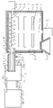
Fig. 1 is a schematic view of a sectional structure of the main view direction of the present invention;
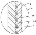
FIG. 2 is an enlarged view of the structure of the utility model 1-A;
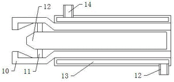
fig. 3 is an enlarged schematic view of the mouthpiece and the core mold of the present invention.
In the figure: 1. a tank body; 2. a first driving motor; 3. a feed hopper; 4. a stirring rod; 5. stirring blades; 6. heating the pipeline; 7. helical leaves; 8. a rotating shaft; 9. a second drive motor; 10. a neck ring mold; 11. a connecting member; 12. a core mold; 13. a cold water pipe; 14. a water inlet pipe orifice; 15. a water outlet pipe orifice; 16. a water inlet hose; 17. a water pump I; 18. a first water tank; 19. a water outlet hose; 20. a second water tank; 21. a second water pump; 22. a connecting pipe; 23. a housing; 24. and (7) an insulating layer.
Detailed Description
The technical solutions in the embodiments of the present invention will be described clearly and completely with reference to the accompanying drawings in the embodiments of the present invention, and it is obvious that the described embodiments are only some embodiments of the present invention, not all embodiments. Based on the embodiments in the present invention, all other embodiments obtained by a person skilled in the art without creative work belong to the protection scope of the present invention.
The first embodiment is as follows:
referring to fig. 1-3, the present invention provides a technical solution: cable sheath pipe extrusion moulding equipment, which comprises a tank body 1, the top of the jar body 1 is provided with driving motor 2 No. one, driving motor 2's output shaft extends to jar body 1's inside and fixedly connected with puddler 4, the outer wall fixedly connected with stirring leaf 5 of puddler 4, the top of the jar body 1 is provided with feeder hopper 3, the lateral wall of the jar body 1 is provided with driving motor 9 No. two, driving motor 9's output shaft extends to jar body 1's inside and fixedly connected with pivot 8, pivot 8's outer wall fixedly connected with spiral leaf 7, the inner wall fixedly connected with heating tube 6 of the jar body 1, the lateral wall of the jar body 1 is provided with bush 10, bush 10 is through being provided with connecting piece 11 fixedly connected with mandrel 12, No. two driving motor 9's one end and bush 10's import looks adaptation are kept.
In this embodiment, add the material to the jar body 1 in through feeder hopper 3, start driving motor 2 No. one, driving motor 2 drives puddler 4 and rotates, puddler 4 drives stirring leaf 5 and rotates, make the material be heated evenly, make it melt through continuous heating of heating tube 6 to the material, restart driving motor 9 No. two, drive pivot 8 and rotate, and then drive the rotation of spiral leaf 7, make the material that is melted of jar body 1 bottom impel to bush 10, when the material increases to a definite time, the material after melting can be extruded in bush 10, and continuously impel, then pass through mandrel 12, extrude from the export of bush 10 at last, prevented that can not fully melt and cause feed cylinder blocking phenomenon, make the raw materials flow out unsmoothly, production quality has been improved.
Example two:
as shown in fig. 1-3, on the basis of the first embodiment, the utility model provides a technical solution: the outer wall of the mouth mold 10 is sleeved with a cold water pipe 13, the outer wall of the top of the cold water pipe 13 is provided with a water inlet pipe orifice 14, the outer wall of the bottom of the cold water pipe 13 is provided with a water outlet pipe orifice 15, the outer wall of the water inlet pipe orifice 14 is fixedly connected with a water inlet hose 16, one end of the water inlet hose 16, which is far away from the water inlet pipe orifice 14, is fixedly connected with a first water pump 17, the side wall of the first water pump 17 is fixedly connected with a first water tank 18, the outer wall of the water outlet pipe orifice 15 is fixedly connected with a water outlet hose 19, one end of the water outlet hose 19, which is far away from the water outlet pipe orifice 15, is fixedly connected with a second water tank 20, the side wall of the second water tank 20 is provided with a second water pump 21, an output shaft of the second water pump 21 is fixedly connected with a connecting pipe 22, one end of the connecting pipe 22, which, the connecting piece 11 is a columnar structure, and cold water is arranged inside the first water tank 18 and the second water tank 20.
In this embodiment, start a water pump 17 and No. two water pump 21, No. one water pump 17 pumps the cold water in 18 water tanks to cold water pipe 13 through water inlet hose 16 in, then through outlet pipe mouth 15 and outlet hose 19 water to No. two water tanks 20, water after the absorbed heat fuses in No. two water tanks 20 and pumps to 18 water tanks through No. two water pump 21 and connecting pipe 22 after the cooling, so circulate, reach the quick cooling of the extrusion pipe of bush 10, the water resource has been practiced thrift simultaneously, cooling channel covers surface temperature stability, the insulating layer surface of having avoided extruding has the ripple, the cable quality has been improved.
Example three:
as shown in fig. 1-3, on the basis of the first embodiment and the second embodiment, the utility model provides a technical solution: the tank body 1 comprises a shell 23, and the inner wall of the shell 23 is provided with an insulating layer 24.
In this embodiment, heat preservation 24 plays the effect of stable heat preservation to the internal 1 of jar, prevents thermal giving off, extravagant heat energy, has reduced manufacturing cost.
The utility model discloses a theory of operation and use flow: when the water-saving water tank is used, materials are added into the tank body 1 through the feed hopper 3, the first driving motor 2 is started, the first driving motor 2 drives the stirring rod 4 to rotate, the stirring rod 4 drives the stirring blades 5 to rotate, the materials are heated uniformly, the materials are continuously heated through the heating pipeline 6 to be melted, the second driving motor 9 is started to drive the rotating shaft 8 to rotate, the spiral blades 7 are further driven to rotate, the spiral blades 7 rotate, the melted materials at the bottom of the tank body 1 are pushed into the neck mold 10, when the materials are increased to a certain level, the melted materials are extruded into the neck mold 10 and are continuously pushed, then the materials pass through the core mold 12 and are finally extruded out of an outlet of the neck mold 10, during the period, the first water pump 17 and the second water pump 21 are started, the first water pump 17 pumps cold water in the first water tank 18 into the cold water pipe 13 through the water inlet hose 16, and then water is discharged into the second water tank 20 through the water outlet 15 and the water outlet hose 19, water after absorbing the heat fuses in No. two water tanks 20 and takes out No. one water tank 18 through No. two water pump 21 and connecting pipe 22 after the cooling, so circulate, reach the quick cooling of the extrusion pipe of bush 10, practiced thrift the water resource simultaneously.
Although embodiments of the present invention have been shown and described, it will be appreciated by those skilled in the art that changes, modifications, substitutions and alterations can be made in these embodiments without departing from the principles and spirit of the invention, the scope of which is defined in the appended claims and their equivalents.
Claims (7)
1. Cable sheath pipe extrusion moulding equipment, including jar body (1), its characterized in that: the top of the tank body (1) is provided with a first driving motor (2), the output shaft of the first driving motor (2) extends into the tank body (1) and is fixedly connected with a stirring rod (4), the outer wall of the stirring rod (4) is fixedly connected with a stirring blade (5), the top of the tank body (1) is provided with a feed hopper (3), a second driving motor (9) is arranged on the side wall of the tank body (1), an output shaft of the second driving motor (9) extends into the tank body (1) and is fixedly connected with a rotating shaft (8), the outer wall of the rotating shaft (8) is fixedly connected with a spiral blade (7), the inner wall of the tank body (1) is fixedly connected with a heating pipeline (6), the side wall of the tank body (1) is provided with an opening mold (10), and the opening mold (10) is fixedly connected with a core mold (12) through a connecting piece (11).
2. The cable sheathing tube extrusion molding apparatus as claimed in claim 1, wherein: the water cooling device is characterized in that a cold water pipe (13) is sleeved on the outer wall of the neck mold (10), a water inlet pipe orifice (14) is arranged on the outer wall of the top of the cold water pipe (13), a water outlet pipe orifice (15) is arranged on the outer wall of the bottom of the cold water pipe (13), a water inlet hose (16) is fixedly connected to the outer wall of the water inlet pipe orifice (14), a first water pump (17) is fixedly connected to one end, away from the water inlet pipe orifice (14), of the water inlet hose (16), a first water tank (18) is fixedly connected to the side wall of the first water pump (17), a water outlet hose (19) is fixedly connected to the outer wall of the water outlet pipe orifice (15), a second water tank (20) is fixedly connected to one end, away from the water outlet pipe orifice (15), of the water outlet hose (19), a second water tank (20) is fixedly connected to, one end of the connecting pipe (22) far away from the second water pump (21) is fixedly connected with the first water tank (18).
3. The cable sheathing tube extrusion molding apparatus as claimed in claim 1, wherein: the tank body (1) comprises a shell (23), and a heat insulation layer (24) is arranged on the inner wall of the shell (23).
4. The cable sheathing tube extrusion molding apparatus as claimed in claim 2, wherein: the pipe wall of the cold water pipe (13) is of a hollow structure, two ends of the cold water pipe (13) are of closed structures, and the caliber of the cold water pipe (13) is matched with that of the neck mold (10).
5. The cable sheathing tube extrusion molding apparatus as claimed in claim 1, wherein: the connecting piece (11) is of a columnar structure.
6. The cable sheathing tube extrusion molding apparatus as claimed in claim 1, wherein: one end of the spiral blade (7) far away from the second driving motor (9) is matched with an inlet of the mouth mold (10).
7. The cable sheathing tube extrusion molding apparatus as claimed in claim 2, wherein: and cold water is arranged in the first water tank (18) and the second water tank (20).
Priority Applications (1)
| Application Number | Priority Date | Filing Date | Title |
|---|---|---|---|
| CN202022588996.6U CN213533703U (en) | 2020-11-11 | 2020-11-11 | Cable sheath pipe extrusion moulding equipment |
Applications Claiming Priority (1)
| Application Number | Priority Date | Filing Date | Title |
|---|---|---|---|
| CN202022588996.6U CN213533703U (en) | 2020-11-11 | 2020-11-11 | Cable sheath pipe extrusion moulding equipment |
Publications (1)
| Publication Number | Publication Date |
|---|---|
| CN213533703U true CN213533703U (en) | 2021-06-25 |
Family
ID=76481374
Family Applications (1)
| Application Number | Title | Priority Date | Filing Date |
|---|---|---|---|
| CN202022588996.6U Expired - Fee Related CN213533703U (en) | 2020-11-11 | 2020-11-11 | Cable sheath pipe extrusion moulding equipment |
Country Status (1)
| Country | Link |
|---|---|
| CN (1) | CN213533703U (en) |
Cited By (1)
| Publication number | Priority date | Publication date | Assignee | Title |
|---|---|---|---|---|
| CN113459457A (en) * | 2021-07-01 | 2021-10-01 | 刘亮亮 | Preparation facilities of HDPE tubular product |
-
2020
- 2020-11-11 CN CN202022588996.6U patent/CN213533703U/en not_active Expired - Fee Related
Cited By (1)
| Publication number | Priority date | Publication date | Assignee | Title |
|---|---|---|---|---|
| CN113459457A (en) * | 2021-07-01 | 2021-10-01 | 刘亮亮 | Preparation facilities of HDPE tubular product |
Similar Documents
| Publication | Publication Date | Title |
|---|---|---|
| CN108995171B (en) | Extruder with crushing function for processing electric wires and cables | |
| CN103350497A (en) | Special precision extrusion system for polyvinylidene fluoride | |
| CN206870336U (en) | PVC sheet processing screw extruder | |
| CN210617244U (en) | Cooling device for plastic pipe extrusion | |
| CN112706384A (en) | Extruding machine with extrusion molding head controlled in real time and operation method thereof | |
| CN219446078U (en) | PVC cable material extrusion granulator | |
| CN208629869U (en) | A kind of production equipment of physical blowing extruded product | |
| CN215472995U (en) | An extruder for plastic processing with overheating protection | |
| CN214000485U (en) | Extrusion device for plastic pipe | |
| CN205130345U (en) | Plasticization machine with filtration | |
| CN111873362B (en) | Extruder for producing plastic mpp power cable protection pipe | |
| CN203317725U (en) | Special precision extrusion device for polyvinylidene fluoride (PVDF) | |
| CN117207474A (en) | Screw extruder for producing ES fibers and extrusion method thereof | |
| CN212312718U (en) | a screw extruder | |
| CN212860354U (en) | Extruder is used in black masterbatch production | |
| CN210121960U (en) | Extrusion moulding machine for plastic production | |
| CN211542308U (en) | Plastic extruder of single screw rod for plastic film production | |
| CN204249279U (en) | A kind of can the injecting machine material tube that cools fast of homogeneous heating | |
| CN210733235U (en) | Blow molding machine with quick feeding function | |
| CN211683395U (en) | Thermoplastic's extrusion moulding equipment | |
| CN211221945U (en) | A extrude structure for nylon production | |
| CN207711331U (en) | A kind of hollow spiral tube tubing production equipment | |
| CN111730871A (en) | Manufacturing process of internal thread reinforced plastic pipe convenient to assemble | |
| CN218876225U (en) | Double-screw extruder | |
| CN214726344U (en) | Intelligent pipe production extruder |
Legal Events
| Date | Code | Title | Description |
|---|---|---|---|
| GR01 | Patent grant | ||
| GR01 | Patent grant | ||
| CF01 | Termination of patent right due to non-payment of annual fee | ||
| CF01 | Termination of patent right due to non-payment of annual fee |
Granted publication date: 20210625 |