CN213531807U - Numerical control lathe material piece collection device - Google Patents
Numerical control lathe material piece collection device Download PDFInfo
- Publication number
- CN213531807U CN213531807U CN202022232524.7U CN202022232524U CN213531807U CN 213531807 U CN213531807 U CN 213531807U CN 202022232524 U CN202022232524 U CN 202022232524U CN 213531807 U CN213531807 U CN 213531807U
- Authority
- CN
- China
- Prior art keywords
- main body
- wall
- collection device
- bottom end
- fixed block
- Prior art date
- Legal status (The legal status is an assumption and is not a legal conclusion. Google has not performed a legal analysis and makes no representation as to the accuracy of the status listed.)
- Expired - Fee Related
Links
- 239000000463 material Substances 0.000 title claims abstract description 20
- 239000002699 waste material Substances 0.000 claims abstract description 24
- 230000001681 protective effect Effects 0.000 claims description 6
- 238000004140 cleaning Methods 0.000 abstract description 5
- 238000009776 industrial production Methods 0.000 abstract description 2
- 238000000034 method Methods 0.000 description 5
- 238000005520 cutting process Methods 0.000 description 3
- 238000009825 accumulation Methods 0.000 description 2
- 230000009286 beneficial effect Effects 0.000 description 1
- 238000001514 detection method Methods 0.000 description 1
- 238000010586 diagram Methods 0.000 description 1
- 238000006073 displacement reaction Methods 0.000 description 1
- 238000005553 drilling Methods 0.000 description 1
- 230000007774 longterm Effects 0.000 description 1
- 238000003754 machining Methods 0.000 description 1
- 239000007921 spray Substances 0.000 description 1
Images


Landscapes
- Auxiliary Devices For Machine Tools (AREA)
Abstract
The utility model discloses a numerical control lathe material piece collection device relates to industrial production technical field, comprising a main body, the top fixed mounting of main part has the fan, the below of fan is connected with the air gun, the guard gate is connected to one side of main part, No. two handles have been seted up to the outer wall of guard gate, the bottom of main part is provided with the base, the baffle box has been seted up to the top that the top of stock guide is located the bottom of main part, the fixed block is installed to the bottom inner wall of main part, the top sliding connection of fixed block has the workstation, the top of fixed block is connected with the nut. The utility model discloses a set up baffle box, stock guide and can reduce piling up at the workstation with the leading-in dirty tank of flying chips of during operation, through setting up the air gun, can be better with the waste material clearance, improved the cleaning efficiency of waste material, through setting up dirty tank, slider, be convenient for take out the clearance with the dirty tank of having collected the waste material.
Description
Technical Field
The utility model relates to an industrial production technical field specifically is a numerical control lathe material piece collection device.
Background
The numerically controlled lathe is one of the widely used numerically controlled machines at present. The cutting tool is mainly used for cutting and processing inner and outer cylindrical surfaces of shaft parts or disc parts, inner and outer conical surfaces with any taper angles, complex rotary inner and outer curved surfaces, cylindrical threads, conical threads and the like, and can perform grooving, drilling, reaming, boring and the like. The numerical control machine tool automatically processes the processed parts according to a processing program programmed in advance. The machining process route, process parameters, tool motion track, displacement, cutting parameters and auxiliary functions of the part are compiled into a machining program list according to instruction codes and program formats specified by the numerical control machine, and then the content in the program list is recorded on a control medium and then input into a numerical control device of the numerical control machine, so that the machine tool is instructed to machine the part.
But current numerical control lathe turns the piece at the in-process of turning and splashes everywhere, is difficult for cleaning, and long-term accumulation does not clean the life that can reduce the machine moreover, and the work piece can splash at the in-process piece of turning, can cause the potential safety hazard to the workman, carries out the cleaning process to the turning piece at every turn and hardly clears up clean up, also is difficult to collect, brings inconvenience for the use.
SUMMERY OF THE UTILITY MODEL
The utility model aims to provide a: in order to solve the problem that the flying chips are inconvenient to clean and the working efficiency is easily influenced, a material chip collecting device of a numerical control lathe is provided.
In order to achieve the above object, the utility model provides a following technical scheme: the utility model provides a numerical control lathe material piece collection device, includes the main part, the top fixed mounting of main part has the fan, the below of fan is connected with the air gun, the guard gate is connected to one side of main part, No. two handles have been seted up to the outer wall of guard gate, the bottom of main part is provided with the base, the slider is installed to the inner wall bottom of base, the dirty tank is installed to the top of slider, No. one handle has been seted up to the outer wall of dirty tank, the stock guide is installed to the top of dirty tank, the top of stock guide is located the bottom of main part and has been seted up the stock guide, the fixed block is installed to the bottom inner wall of main part, the top sliding connection of fixed block has the workstation, the top of.
Preferably, the top end inner wall of the main body is provided with a sliding groove matched with the protective door.
Preferably, the top end of the material guide plate is matched with the bottom end of the main body.
Preferably, the bottom end of the workbench is provided with a sliding block matched with the fixed block.
Preferably, the bottom end of the waste material groove is provided with a groove matched with the sliding block.
Preferably, the fixed block is detachably connected with the inner wall of the bottom end of the main body through a nut.
Compared with the prior art, the beneficial effects of the utility model are that: the utility model discloses a set up baffle box, stock guide and can reduce piling up at the workstation with the leading-in dirty tank of flying chips of during operation, through setting up the air gun, can be better with the waste material clearance, improved the cleaning efficiency of waste material, through setting up dirty tank, slider, be convenient for take out the clearance with the dirty tank of having collected the waste material.
Drawings
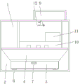
Fig. 1 is a perspective view of the present invention;
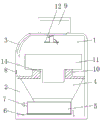
FIG. 2 is a schematic structural view of the present invention;
FIG. 3 is a schematic connection diagram of the present invention;
fig. 4 is a schematic view of the connection of the workbench according to the present invention.
In the figure: 1. a main body; 2. a base; 3. a protective door; 4. a material guide plate; 5. a waste chute; 6. a slider; 7. a first handle; 8. a second handle; 9. a fan; 10. a fixed block; 11. a work table; 12. a wind gun; 13. a nut; 14. a material guide groove.
Detailed Description
The technical solutions in the embodiments of the present invention will be described clearly and completely with reference to the accompanying drawings in the embodiments of the present invention, and it is obvious that the described embodiments are only some embodiments of the present invention, not all embodiments. Based on the embodiments in the present invention, all other embodiments obtained by a person skilled in the art without creative work belong to the protection scope of the present invention.
The fan (model: DHBFG) mentioned in the utility model can be obtained by market or private ordering.
Please refer to fig. 1-4, a collection device for material scraps of a numerical control lathe comprises a main body 1, a fan 9 is fixedly installed above the main body 1, an air gun 12 is connected below the fan 9, a protection door 3 is connected to one side of the main body 1, a second handle 8 is arranged on the outer wall of the protection door 3, a base 2 is arranged at the bottom end of the main body 1, a sliding block 6 is installed at the bottom end of the inner wall of the base 2, a waste chute 5 is installed above the sliding block 6, a first handle 7 is arranged on the outer wall of the waste chute 5, a material guide plate 4 is installed above the waste chute 5, a material guide groove 14 is arranged at the bottom end of the main body 1 above the material guide plate 4, a fixed block 10 is installed on the inner wall of the bottom end of the main body 1, a workbench 11.
Please refer to fig. 1, the top inner wall of the main body 1 is provided with a sliding slot matching with the protection door 3, the protection door 3 moves up and down through the sliding slot arranged on the inner wall of the main body 1, so as to be convenient for opening and closing, and can effectively protect the working personnel when the working platform 11 works.
Please refer to fig. 2, the top end of the guiding plate 4 is engaged with the bottom end of the main body 1, and the guiding plate 4 is installed at the bottom end of the main body 1, so as to effectively guide the flying chips falling from the worktable 11 into the waste chute 5.
Please refer to fig. 4, the bottom of the working platform 11 is provided with a sliding block under the sliding block working platform 11 matching with the fixed block 10, which can effectively fix the working platform 11 above the fixed block 10 to prevent the working platform 11 from falling off.
Please refer to fig. 2, the bottom of the waste material tank 5 is provided with a groove matched with the sliding block 6, the waste material tank 5 slides above the sliding block 6 through the sliding groove, and the waste material tank 5 can be installed and moved out after the sliding block 6 slides, so that the waste material tank 5 is convenient to clean.
Please refer to fig. 4, the fixing block 10 is detachably connected to the inner wall of the bottom end of the main body 1 through the nut 13, so that the fixing block 10 can be effectively mounted and dismounted for facilitating detection and cleaning.
The working principle is as follows: firstly, when the workbench 11 performs the numerical control turning work, and the fan 9 operates, the air gun 12 sprays air aiming at the position of the workbench 11, the flying chips of the workbench 11 are blown out of the surface position of the workbench 11, the accumulation of flying chips or waste materials is reduced, the flying chips blown by the air gun 12 wound on the fixing frame arranged on the inner wall of the top end of the main body 1 fall into the guide chute 14, the waste materials entering the guide chute 14 are guided into the waste chute 5 by the guide plate 4 and accumulated in the waste chute 5 because the guide plate 4 arranged below the guide chute 14 is an inverted trapezoidal plate inclined inwards, after the workbench 11 stops the numerical control turning work, a worker can push the air gun 12 upwards through the second handle 8 to open the protective door 3, then the air gun 12 is taken down from the fixing frame arranged below the top end of the main body 1, and then the hand-held air gun 12 blows the flying chips adhered on the inner wall of the main body 1 into the guide chute 14, the flying chips that will fall into the flange of 11 below fixed plates 10 of workstation will fly the bits and blow in the chute of stock guide 4 through the hole that fixed plate 10 set up to leading-in chute 5, after clearing up, close fan 9, then through a handle 7 pulling chute 5, then pull out chute 5 through the spout in the top of slider 6, clear up chute 5.
It is obvious to a person skilled in the art that the invention is not restricted to details of the above-described exemplary embodiments, but that it can be implemented in other specific forms without departing from the spirit or essential characteristics of the invention. The present embodiments are therefore to be considered in all respects as illustrative and not restrictive, the scope of the invention being indicated by the appended claims rather than by the foregoing description, and all changes which come within the meaning and range of equivalency of the claims are therefore intended to be embraced therein. Any reference sign in a claim should not be construed as limiting the claim concerned.
Claims (6)
1. A numerical control lathe material piece collection device, includes main part (1), its characterized in that: the air blower is characterized in that a fan (9) is fixedly mounted above the main body (1), an air gun (12) is connected below the fan (9), a protective door (3) is connected to one side of the main body (1), a second handle (8) is arranged on the outer wall of the protective door (3), a base (2) is arranged at the bottom end of the main body (1), a sliding block (6) is mounted at the bottom end of the inner wall of the base (2), a waste chute (5) is mounted above the sliding block (6), a first handle (7) is arranged on the outer wall of the waste chute (5), a guide plate (4) is mounted above the waste chute (5), a guide chute (14) is arranged at the bottom end of the main body (1) above the guide plate (4), a fixed block (10) is mounted on the inner wall at the bottom end of the main body (1), and a workbench (11) is slidably connected above the fixed, and a nut (13) is connected above the fixed block (10).
2. A numerically controlled lathe material debris collection device as in claim 1, wherein: the top end inner wall of the main body (1) is provided with a sliding groove matched with the protective door (3).
3. A numerically controlled lathe material debris collection device as in claim 1, wherein: the top end of the material guide plate (4) is matched with the bottom end of the main body (1).
4. A numerically controlled lathe material debris collection device as in claim 1, wherein: and a sliding block matched with the fixed block (10) is arranged at the bottom end of the workbench (11).
5. A numerically controlled lathe material debris collection device as in claim 1, wherein: the bottom end of the waste material groove (5) is provided with a groove matched with the sliding block (6).
6. A numerically controlled lathe material debris collection device as in claim 1, wherein: the fixed block (10) is detachably connected with the inner wall of the bottom end of the main body (1) through a nut (13).
Priority Applications (1)
| Application Number | Priority Date | Filing Date | Title |
|---|---|---|---|
| CN202022232524.7U CN213531807U (en) | 2020-10-10 | 2020-10-10 | Numerical control lathe material piece collection device |
Applications Claiming Priority (1)
| Application Number | Priority Date | Filing Date | Title |
|---|---|---|---|
| CN202022232524.7U CN213531807U (en) | 2020-10-10 | 2020-10-10 | Numerical control lathe material piece collection device |
Publications (1)
| Publication Number | Publication Date |
|---|---|
| CN213531807U true CN213531807U (en) | 2021-06-25 |
Family
ID=76496118
Family Applications (1)
| Application Number | Title | Priority Date | Filing Date |
|---|---|---|---|
| CN202022232524.7U Expired - Fee Related CN213531807U (en) | 2020-10-10 | 2020-10-10 | Numerical control lathe material piece collection device |
Country Status (1)
| Country | Link |
|---|---|
| CN (1) | CN213531807U (en) |
-
2020
- 2020-10-10 CN CN202022232524.7U patent/CN213531807U/en not_active Expired - Fee Related
Similar Documents
| Publication | Publication Date | Title |
|---|---|---|
| CN214212280U (en) | Automatic high-power punching machine tool | |
| CN217749456U (en) | Mould processing perforating device with piece collection mechanism | |
| CN211252012U (en) | Self-cleaning formula engraver | |
| CN210254266U (en) | Precise numerical control lathe | |
| CN112122966B (en) | Numerical control machine tool workpiece clamping device with angle adjusting function | |
| CN211489707U (en) | Radial drill convenient to retrieve coolant liquid | |
| CN116038411A (en) | A kind of anti-splash mechanism of numerical control processing equipment and using method thereof | |
| CN117140169B (en) | A protection mechanism for CNC machine tools | |
| CN116690283A (en) | A kind of mechanical processing machine tool with convenient chip removal | |
| CN217966133U (en) | Iron scrap protective device for milling of plates | |
| CN211332388U (en) | Efficient protection device for machine tool cuttings | |
| CN213104663U (en) | Small-size automatic drilling machine for machining | |
| CN210849394U (en) | Numerical control lathe is with receiving device convenient to clearance is filterable | |
| CN116652679A (en) | Five-axis numerical control machining center with automatic point searching structure | |
| CN220093965U (en) | Numerical control double-end lathe | |
| CN220515435U (en) | Multi-station numerical control lathe | |
| CN207915109U (en) | A kind of Metal Cutting Machine Tool that can prevent metal fillings from splashing | |
| CN216326957U (en) | High-precision numerical control lathe | |
| CN215317345U (en) | Digit control machine tool with supplementary clear useless mechanism | |
| CN218984108U (en) | lathe protective cover | |
| CN215616584U (en) | Breakage-proof bits device that splashes that digit control machine tool was used | |
| CN221791060U (en) | Prevent vertical lathe protector that waste material splashes | |
| CN220534325U (en) | Cutting machine with safeguard function | |
| CN222680347U (en) | A chip cleaning structure for a CNC machine tool workbench | |
| CN221774067U (en) | A chip splash prevention component for a drilling machine |
Legal Events
| Date | Code | Title | Description |
|---|---|---|---|
| GR01 | Patent grant | ||
| GR01 | Patent grant | ||
| CF01 | Termination of patent right due to non-payment of annual fee |
Granted publication date: 20210625 Termination date: 20211010 |
|
| CF01 | Termination of patent right due to non-payment of annual fee |