Recovery unit for medical instrument
Technical Field
The utility model relates to the technical field of medical equipment, in particular to a recovery device for medical equipment.
Background
The medical apparatus refers to instruments, equipment, appliances, materials or other articles which are used for human bodies singly or in combination, and comprises required software, the functions of the instruments, the equipment, the appliances, the materials or other articles are not obtained by means of pharmacology, immunology or metabolism, but the instruments can participate in and play a certain auxiliary role, and for the medical apparatus, the most common ones are disposable needle tubes, infusion tubes, medicine bottles and the like, and the medical apparatus needs to be intensively recycled by a water recycling device after being used, but the existing recycling device has the following problems when being used:
1. in the prior art, the recovery device cannot separately recover and treat the medical waste liquid in the medical apparatus, and a plurality of medical waste liquids are contained in some apparatuses, so that the medical waste liquids are easy to drip and spill in the transferring and carrying processes, so that the environmental pollution is caused, and the health of treatment personnel can be easily influenced after long-time work;
2. in the prior art, the recovery device can not classify, store and disinfect the instruments, a large amount of bacteria can grow on the instruments, bad smell is generated, and treatment personnel are easy to infect.
SUMMERY OF THE UTILITY MODEL
The utility model provides a recovery unit for medical instrument possesses and classify the recovery to medical instrument, can throw away remaining waste liquid on the medical instrument, disinfect and remove the flavor to the apparatus simultaneously, use more sanitary clean advantage, can't retrieve alone the medical waste liquid in the medical instrument in order to solve recovery unit, drip easily and spill, cause environmental pollution, can't classify to these apparatus and deposit and disinfect, can breed a large amount of bacteriums, and produce the problem of the gas of smelling.
To realize categorised the retrieving to medical instrument, can throw away remaining waste liquid on the medical instrument, disinfect and remove the flavor to the apparatus simultaneously, use more sanitary clean purpose, the utility model provides a following technical scheme: a recovery device for medical instruments comprises a box body, wherein a partition plate and a grid plate are fixedly arranged between the inner walls of the box body from bottom to top in sequence, the box body is divided into an installation chamber, a liquid storage chamber and a spin-drying chamber from bottom to top by the partition plate and the grid plate, three groups of rotating mechanisms are uniformly arranged on the upper surface of the grid plate, each rotating mechanism comprises a bearing seat, a transmission rod and a placing frame, the bearing seats are fixedly arranged on the upper surface of the grid plate, the placing frames are fixedly arranged on the bearing seats through the transmission rods, the rotating mechanisms are in transmission connection with a driving mechanism, collecting frames are arranged in the placing frames, round holes are formed in the upper surfaces of the box bodies corresponding to the collecting frames, sealing covers are covered on the round holes, ultraviolet lamps are fixedly arranged on the front inner wall and the, purify the mechanism and include fan, air-supply line, active carbon adsorption case and go out the tuber pipe, fan fixed mounting is in the installation room, the air intake of fan is linked together through air-supply line and spin-dry chamber, be provided with active carbon adsorption case on the air-supply line, and active carbon adsorption case fixed mounting is in the box right flank, the air outlet of fan is linked together through going out the tuber pipe and spin-dry chamber.
As a preferred technical scheme of the utility model, the corresponding box leading flank of installation room is provided with the closing plate, the corresponding box left surface of stock solution room sets up the flowing back valve.
As a preferred technical scheme of the utility model, actuating mechanism includes motor, pivot, fluted disc and chain, motor fixed mounting is indoor in the installation, fixed mounting has the pivot on the output shaft of motor, and the pivot is connected with middle transfer line, fluted disc fixed mounting is on the transfer line, and the fluted disc passes through chain drive and connects.
As a preferred technical scheme of the utility model, the pivot all is provided with the sealing member with the corresponding position of play tuber pipe and baffle, the through-hole has all been seted up with the corresponding position of play tuber pipe and grating to the pivot.
As an optimal technical scheme of the utility model, be provided with the battery that provides the electric energy for motor and fan in the installation room.
As an optimal technical scheme of the utility model, the box lower surface is rectangle fixed mounting has the gyro wheel, box right flank fixed mounting has the handle.
Compared with the prior art, the utility model provides a recovery unit for medical instrument possesses following beneficial effect:
1. this recovery unit for medical instrument drives the rack rotation in the rotary mechanism through setting up actuating mechanism, makes the rack drive and collects the frame rotation, can throw away remaining waste liquid on the medical instrument, makes medical instrument rapid draing, drips when avoiding the transport and spills the waste liquid to the treatment staff also can not contact with the waste liquid, and the three frame of collecting is convenient for classify and retrieve medical instrument.
2. This recovery unit for medical instrument can disinfect to collecting interior instrument of frame through setting up ultraviolet lamp, and the rethread purifies in the mechanism fan makes gas circulation in the box to adsorb through activated carbon adsorption case to the interior bad smell peculiar smell of box and purify, effectively avoid cross infection, use more sanitary clean.
Drawings
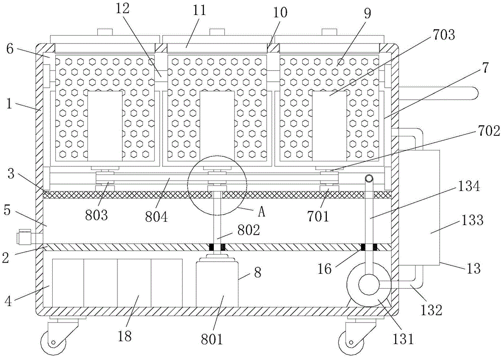
Fig. 1 is a schematic structural view of the present invention;
fig. 2 is a cross-sectional view of the present invention;
fig. 3 is an enlarged view of the position a of the present invention.
In the figure: 1. a box body; 2. a partition plate; 3. a grid plate; 4. an installation chamber; 5. a liquid storage chamber; 6. a drying chamber; 7. a rotation mechanism; 701. a bearing seat; 702. a transmission rod; 703. placing a rack; 8. a drive mechanism; 801. a motor; 802. a rotating shaft; 803. a fluted disc; 804. a chain; 9. a collection frame; 10. a circular hole; 11. A sealing cover; 12. an ultraviolet lamp; 13. a purification mechanism; 131. a fan; 132. an air inlet pipe; 133. an activated carbon adsorption tank; 134. an air outlet pipe; 14. a sealing plate; 15. a drain valve; 16. a seal member; 17. a through hole; 18. a storage battery; 19. a roller; 20. and (4) a handle.
Detailed Description
The technical solutions in the embodiments of the present invention will be described clearly and completely with reference to the accompanying drawings in the embodiments of the present invention, and it is obvious that the described embodiments are only some embodiments of the present invention, not all embodiments. Based on the embodiments in the present invention, all other embodiments obtained by a person skilled in the art without creative work belong to the protection scope of the present invention.
Referring to fig. 1-3, the utility model discloses a recovery device for medical instruments, which comprises a box body 1, a partition plate 2 and a grid plate 3 are fixedly arranged between the inner walls of the box body 1 from bottom to top in sequence, the partition plate 2 and the grid plate 3 divide the box body 1 from bottom to top into an installation chamber 4, a liquid storage chamber 5 and a spin-drying chamber 6, the upper surface of the grid plate 3 is uniformly provided with three groups of rotating mechanisms 7, each rotating mechanism 7 comprises a bearing seat 701, a transmission rod 702 and a placing rack 703, the bearing seat 701 is fixedly arranged on the upper surface of the grid plate 3, the placing rack 703 is fixedly arranged on the bearing seat 701 through the transmission rod 702, the rotating mechanisms 7 are in transmission connection with a driving mechanism 8, collecting frames 9 are all placed in the placing rack 703, the upper surfaces of the box bodies 1 corresponding to the collecting frames 9 are all provided with round holes 10, equal fixed mounting has ultraviolet lamp 12 on the inner wall around the corresponding box 1 of dry room 6, be provided with on the box 1 and purify mechanism 13, it includes fan 131, air-supply line 132, activated carbon adsorption case 133 and goes out tuber pipe 134 to purify mechanism 13, fan 131 fixed mounting is in installation room 4, the air intake of fan 131 is linked together through air-supply line 132 and dry room 6, be provided with activated carbon adsorption case 133 on the air-supply line 132, and activated carbon adsorption case 133 fixed mounting is in the 1 right flank of box, and activated carbon adsorption case 133 sets up in the box 1 outside, is convenient for change the activated carbon, the air outlet of fan 131 is linked together through going out tuber pipe 134 and dry room 6.
Specifically, a sealing plate 14 is arranged on the front side surface of the box body 1 corresponding to the mounting chamber 4, and a drain valve 15 is arranged on the left side surface of the box body 1 corresponding to the liquid storage chamber 5.
In this embodiment, the sealing plate 14 is mounted by a locking bolt, so that the sealing plate 14 is detachable, and the driving mechanism 8 and the purifying mechanism 13 are inspected.
Specifically, the driving mechanism 8 includes a motor 801, a rotating shaft 802, a toothed disc 803 and a chain 804, the motor 801 is fixedly installed in the installation chamber 4, the rotating shaft 802 is fixedly installed on an output shaft of the motor 801, the rotating shaft 802 is connected with a transmission rod 702 in the middle, the toothed disc 803 is fixedly installed on the transmission rod 702, and the toothed disc 803 is in transmission connection through the chain 804.
In this embodiment, the motor 801 drives the middle transmission rod 702 to rotate through the rotation shaft 802, so that the transmission rod 702 drives the two side tooth discs 803 to rotate through the middle tooth disc 803 and the chain 804, and the two side transmission rods 702 rotate.
Specifically, the sealing elements 16 are arranged at the positions corresponding to the rotating shaft 802 and the air outlet pipe 134 and the partition plate 2, and the through holes 17 are arranged at the positions corresponding to the rotating shaft 802 and the air outlet pipe 134 and the grid plate 3.
In this embodiment, the sealing member 16 prevents the waste liquid in the liquid storage chamber 5 from entering the installation chamber 4, and the through hole 17 facilitates the rotation shaft 802 and the air outlet pipe 134 to pass through the grid plate 3.
Specifically, a storage battery 18 for supplying electric power to the motor 801 and the fan 131 is provided in the installation chamber 4.
In this embodiment, the storage battery 18 can provide electric energy for the motor 801 and the fan 131, so that the recycling device can be conveniently used in an environment without an external power supply.
Specifically, the lower surface of the box body 1 is rectangular and is fixedly provided with a roller 19, and the right side of the box body 1 is fixedly provided with a handle 20.
In this embodiment, the roller 19 is engaged with the handle 20 to facilitate the movement of the recycling device.
The utility model discloses a theory of operation and use flow: when in use, the sealing cover 11 is opened to place the corresponding medical apparatus in the corresponding collecting frame 9, the sealing cover 11 is covered, the motor 801 in the driving mechanism 8 drives the middle transmission rod 702 to rotate through the rotating shaft 802, the middle transmission rod 702 drives the two side fluted discs 803 to rotate through the middle fluted disc 803 and the chain 804, the two side transmission rods 702 rotate, the transmission rod 702 drives the collecting frame 9 on the placing frame 703 to rotate, the waste liquid remained on the medical apparatus in the collecting frame 9 can be thrown out, the medical apparatus can be rapidly dried, the waste liquid is prevented from dripping during transportation, a treating person can not contact with the waste liquid, the three collecting frames 9 are convenient for classifying and recycling the medical apparatus, the apparatus in the collecting frame 9 can be sterilized through the ultraviolet lamp 12, and then the fan 131 in the purifying mechanism 13 pumps the smelly gas into the activated carbon adsorption box 133 through the air inlet pipe 132, the bad smell in the box body 1 is absorbed and purified, and then the air flows back to the box body 1 through the air outlet pipe 134, so that the cross infection is effectively avoided, and the use is more sanitary and clean.
To sum up, this recovery unit for medical instrument is convenient for classify the recovery to medical instrument, can throw away remaining waste liquid on the medical instrument, drips when avoiding the transport and spills, disinfects and removes the flavor to the apparatus simultaneously, uses more sanitary clean.
It should be noted that, in this document, terms such as "comprises," "comprising," or any other variation thereof, are intended to cover a non-exclusive inclusion, such that a process, method, article, or apparatus that comprises a list of elements does not include only those elements but may include other elements not expressly listed or inherent to such process, method, article, or apparatus. Without further limitation, an element defined by the phrase "comprising an … …" does not exclude the presence of other identical elements in a process, method, article, or apparatus that comprises the element.
Although embodiments of the present invention have been shown and described, it will be appreciated by those skilled in the art that changes, modifications, substitutions and alterations can be made in these embodiments without departing from the principles and spirit of the invention, the scope of which is defined in the appended claims and their equivalents.