Knee joint support for orthopedics
Technical Field
The utility model relates to the technical field of medical equipment, in particular to knee joint support for orthopedics.
Background
The knee joint support is an auxiliary supporting tool worn by a knee joint injury patient after operation, and is very important for the postoperative recovery of the patient. The existing knee joint support is generally bound on a leg part through a binding band, the knee joint support is provided with a knee rotor to match the extension and flexion of the leg part and the angle adjustment, the knee joint support realizes the bearing of a body through the friction force between the binding band and the leg part, so that the friction force between the binding band and the leg part is large, the leg part is easily damaged, and the knee joint support also easily drops downwards in the using process, and the good effect cannot be achieved.
SUMMERY OF THE UTILITY MODEL
Therefore, the utility model provides a knee joint support for orthopedics can reduce the frictional force of mounting and lower mounting to the shank, alleviates the damage to the shank, improves the bearing effect, is applicable to the shank of equidimension not simultaneously.
The technical scheme of the utility model is realized like this:
the utility model provides a knee joint support for orthopedics, includes foot's support piece, is fixed in the last mounting of thigh and is fixed in the lower mounting of shank, go up the mounting pass through the knee rotor with the mounting is connected down, foot's support piece with the connection is dismantled to mounting down, foot's support piece is used for supporting mounting down, foot's support piece includes footboard, flexible bracing piece and first fixed band, the both sides of footboard are connected with respectively flexible bracing piece, the both sides of first fixed band are connected with the slide bar, the free end of slide bar through first spring with flexible bracing piece sliding connection, the free end of flexible bracing piece through the fixing base be connected with mounting complex locking device down.
Further, the upper fixing piece and the lower fixing piece respectively comprise a plurality of second fixing belts, fixing plates are connected to two sides of the second fixing belts respectively, two ends of the second fixing belts are detachably connected, and the fixing plates of the upper fixing piece are connected with the fixing plates of the lower fixing piece through the knee rotor.
Further, locking device includes L type locking plate and adjusting button, L type locking plate with fixing base sliding connection, the adjusting button rotate connect in on the fixing base, the one end of L type locking plate is connected with the screw rod, the free end of screw rod with adjusting button threaded connection, the mounting is equipped with down and is corresponding to the locking groove of L type locking plate, L type locking plate with locking groove mutually supports the locking.
Furthermore, one side in locking groove is equipped with the adjustment tank, sliding connection has the latch segment in the adjustment tank, the latch segment pass through the second spring with the bottom of adjustment tank is connected, the latch segment is equipped with the arch, adjustment tank sliding connection has presses bellied unblock pole, the third spring has been cup jointed to the outside of unblock pole.
Furthermore, the upper end of the telescopic supporting rod is provided with a sliding groove, and the first spring and the sliding rod are arranged in the sliding groove.
Furthermore, the first fixing belt is provided with a connecting block, and the sliding rod is connected with the first fixing belt through the connecting block.
Compared with the prior art, the beneficial effects of the utility model are that:
the knee joint support for the orthopedics department provided by the utility model can be fixed on the leg part through the upper fixing part and the lower fixing part, can be connected with the foot supporting part according to the condition of a patient, reduces the friction force of the upper fixing part and the lower fixing part on the leg part, lightens the damage to the leg part and improves the bearing effect; the first fixing strap can play a role in fixing the foot supporting piece to prevent the foot supporting piece from moving up and down relative to the crus, the sliding rods are connected with the telescopic supporting rods through the first springs, the first fixing strap can be close to the crus to be beneficial to fixing the foot supporting piece, the distance between the sliding rods on the left side and the right side can be adjusted, the crus can conveniently extend out or be arranged between the telescopic supporting rods on the left side and the right side, and the crus with different sizes can be matched at; the locking device is slid to align the locking device with the corresponding position of the lower fixing piece, so that the lower fixing piece is suitable for position change of the lower fixing piece when the lower fixing piece fixes crus of different sizes.
Drawings
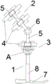
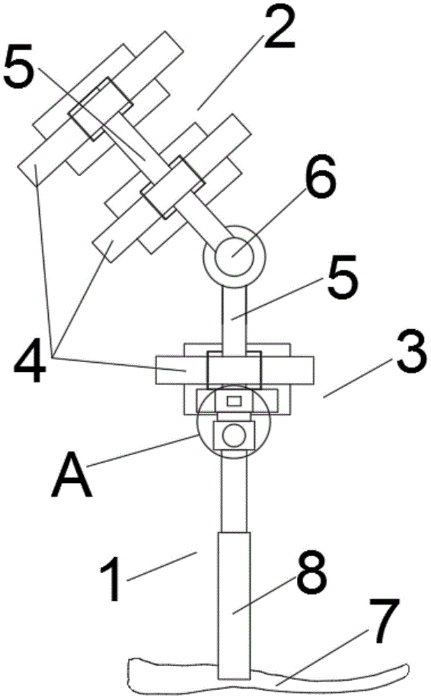
Fig. 1 is a schematic side view of the knee joint support for orthopedics of the present invention;
FIG. 2 is an enlarged schematic view of a portion A of FIG. 1;
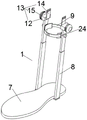
FIG. 3 is a schematic perspective view of the foot support of the present invention;
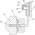
FIG. 4 is a schematic cross-sectional view of the locking connection between the foot supporting member and the lower fixing member of the present invention;
FIG. 5 is a schematic cross-sectional view of the joint between the slide bar and the telescopic support bar of the present invention;
in the figure, a foot supporting piece 1, an upper fixing piece 2, a lower fixing piece 3, a second fixing band 4, a fixing plate 5, a knee rotor 6, a pedal 7, a telescopic supporting rod 8, a first fixing band 9, a sliding rod 10, a first spring 11, a fixing seat 12, a locking device 13, a locking plate 14L, an adjusting button 15, a screw rod 16, a locking groove 17, an adjusting groove 18, a locking block 19, a second spring 20, a bulge 21, an unlocking rod 22, a sliding groove 23 and a connecting block 24 are arranged.
Detailed Description
In order to better understand the technical content of the present invention, the following embodiments are provided, and the present invention is further described with reference to the accompanying drawings.
Example 1
Referring to fig. 1 to 5, the present invention provides a knee joint support for orthopedics, including a foot support member 1, an upper fixing member 2 fixed on the thigh and a lower fixing member 3 fixed on the shank, the upper fixing member 2 and the lower fixing member 3 can make the present invention fixed on the leg, the foot support member 1 can improve the bearing effect and relieve the stress of the knee, the upper fixing member 2 is connected with the lower fixing member 3 through a knee rotor 6, and the knee rotor 6 is matched with the extension and flexion of the knee joint and the adjustment of the angle, wherein the knee rotor 6 is the prior art, which is not described herein any more, the foot support member 1 is connected with the lower fixing member 3 in a detachable manner, the foot support member 1 can be connected according to the condition of the patient, the damage of the upper fixing member 2 and the lower fixing member 3 to the leg is relieved, and the bearing effect is improved, the foot support member 1 is used, The utility model discloses a leg support device, including flexible bracing piece 8 and first fixed band 9, the both sides of footboard 7 are connected with respectively flexible bracing piece 8, wherein are equipped with the bandage on the footboard 7 (not mark), and flexible bracing piece 8 can be adjusted according to patient's shank height, the both sides of first fixed band 9 are connected with slide bar 10, the free end of slide bar 10 through first spring 11 with flexible bracing piece 8 sliding connection, first fixed band 9 can play fixed foot support piece 1's effect, avoids foot support piece 1 to reciprocate for the shank, and slide bar 10 passes through first spring 11 to be connected, can make first fixed band 9 press close to the shank, is favorable to fixed foot support piece 1, and the distance between the adjustable left and right sides slide bar 10, conveniently stretches out or arranges in between the flexible bracing piece 8 of left and right sides in the shank, cooperates not equidimension shank simultaneously, the free end of flexible bracing piece 8 be connected with through fixing base 12 with lower And 13, the locking device 13 can be slid to enable the locking device 13 to be aligned to the corresponding position of the lower fixing piece 3, so that the lower fixing piece 3 and the foot supporting piece 1 are locked, and the lower fixing piece 3 is suitable for position change of the lower fixing piece 3 when the lower fixing piece 3 fixes crus with different sizes.
The working principle is as follows: use the utility model discloses the time, on mounting 2 is fixed in on the thigh, lower mounting 3 is fixed in on the shank, knee rotor 6 is located the side of knee, when shank support piece need be used, the user foot is arranged in on footboard 7, adjust the height of flexible bracing piece 8, make flexible bracing piece 8 extend to mounting 3 department down, to one side slip locking device 13 that is close to the shank, make locking device 13 aim at with mounting 3 down, locking flexible bracing piece 8 and lower mounting 3, to the peripheral first fixed band 9 of pulling that is close to the shank, through the cooperation of first spring 11 and slide bar 10, first fixed band 9 is close to with the shank laminating near the shank, be fixed in on the shank, make on foot support piece 1 stably is fixed in the shank, improve the utility model discloses a bearing effect alleviates the bearing of knee to the health, effectively alleviates the knee joint ailing.
Specifically, the upper fixing part 2 and the lower fixing part 3 both include a plurality of second fixing bands 4, and are a plurality of the two sides of the second fixing bands 4 are respectively connected with a fixing plate 5, and are a plurality of the two ends of the second fixing bands 4 are detachably connected, and the detachable connection can be selected by a buckle connection, and the fixing plate 5 of the upper fixing part 2 is connected with the fixing plate 5 of the lower fixing part 3 through a knee rotor 6. The second fixing belt 4 can fix the fixing plate 5 to the leg, which has the effect of reducing the sitting of the knee.
Specifically, locking device 13 includes L type locking plate 14 and adjusting knob 15, L type locking plate 14 with fixing base 12 sliding connection, adjusting knob 15 rotate connect in on the fixing base 12, the one end of L type locking plate 14 is connected with screw rod 16, the free end of screw rod 16 with adjusting knob 15 threaded connection, lower mounting 3 is equipped with corresponding to L type locking plate 14's locking groove 17, L type locking plate 14 with locking groove 17 mutually supports the locking. When the fixing plate 5 of the lower fixing part 3 is fixed on the lower leg, the diameter of the lower leg is different, so that the locking groove 17 formed in the fixing plate 5 fixed on the lower leg cannot always keep alignment with the L-shaped locking plate 14, when the foot supporting part 1 and the lower fixing part 3 are locked, the adjusting button 15 is twisted, the screw 16 continuously extends outwards from the inside of the adjusting button 15, the L-shaped locking plate 14 is pushed to align with the locking groove 17, the telescopic supporting rod 8 is adjusted upwards, and the L-shaped locking plate 14 is embedded into the locking groove 17 to be locked.
Specifically, one side of locking groove 17 is equipped with adjustment tank 18, sliding connection has latch segment 19 in adjustment tank 18, latch segment 19 through second spring 20 with the bottom of adjustment tank 18 is connected, latch segment 19 is equipped with arch 21, adjustment tank 18 sliding connection has presses protruding 21's unblock pole 22, the third spring (not marked) has been cup jointed to unblock pole 22's outside. After the L-shaped locking plate 14 is embedded into the locking groove 17, the locking block 19 locks the L-shaped locking plate 14 to prevent the foot support 1 from being separated from the lower fixing piece 3, when the foot fixing piece needs to be detached, the unlocking rod 22 is pressed, the unlocking rod 22 enables the locking block 19 to move towards the bottom of the adjusting groove 18 through the protrusion 21, and the locking block 19 is unlocked.
Example 2
Referring to fig. 3 to 5, the present embodiment is different from embodiment 1 in that a sliding groove 23 is formed at an upper end of the telescopic support rod 8, and the first spring 11 and the sliding rod 10 are both disposed in the sliding groove 23. The first spring 11 can reset the sliding rods 10 when the first fixing belt 9 is unfastened, and drives the first fixing belt 9 to approach the ends of the telescopic supporting rods 8, so that the distance between the sliding rods 10 on the left side and the right side is larger than the diameter of the shank, the shank can conveniently extend out of the space between the telescopic supporting rods 8 on the left side and the right side, and the sliding rods 10 play a supporting role.
Specifically, the first fixing strap 9 is provided with a connecting block 24, and the sliding rod 10 is connected with the first fixing strap 9 through the connecting block 24. The connecting block 24 is convenient for fixing the sliding rod 10, and has a good supporting effect.
The above description is only a preferred embodiment of the present invention, and should not be taken as limiting the invention, and any modifications, equivalent replacements, improvements, etc. made within the spirit and principle of the present invention should be included in the protection scope of the present invention.