CN213517337U - Nuclear phase device with built-in circulating water cooling device - Google Patents
Nuclear phase device with built-in circulating water cooling device Download PDFInfo
- Publication number
- CN213517337U CN213517337U CN202022460210.2U CN202022460210U CN213517337U CN 213517337 U CN213517337 U CN 213517337U CN 202022460210 U CN202022460210 U CN 202022460210U CN 213517337 U CN213517337 U CN 213517337U
- Authority
- CN
- China
- Prior art keywords
- spiral pipe
- cooling spiral
- left end
- nuclear phase
- face
- Prior art date
- Legal status (The legal status is an assumption and is not a legal conclusion. Google has not performed a legal analysis and makes no representation as to the accuracy of the status listed.)
- Expired - Fee Related
Links
- 238000001816 cooling Methods 0.000 title claims abstract description 59
- XLYOFNOQVPJJNP-UHFFFAOYSA-N water Substances O XLYOFNOQVPJJNP-UHFFFAOYSA-N 0.000 title claims abstract description 22
- 230000017525 heat dissipation Effects 0.000 abstract description 2
- 238000000034 method Methods 0.000 description 3
- 230000004075 alteration Effects 0.000 description 1
- 230000009286 beneficial effect Effects 0.000 description 1
- 238000012986 modification Methods 0.000 description 1
- 230000004048 modification Effects 0.000 description 1
- 238000006467 substitution reaction Methods 0.000 description 1
Images


Landscapes
- Monitoring And Testing Of Nuclear Reactors (AREA)
Abstract
The utility model relates to the technical field of a nuclear phase device, in particular to a nuclear phase device with a built-in circulating water cooling device, which comprises an insulating shell, wherein the right side surface of the insulating shell is penetrated and fixedly connected with the nuclear phase device, a connecting plate is fixedly arranged between the insulating shell and the phase detector, the left end of the insulating shell is fixedly connected with a fixing piece through a screw I, the left end surface of the phase detector is fixedly connected with a handle, the left end of the fixing piece is movably sleeved with a cooling spiral pipe, the left end surface of the fixing piece is provided with a threaded hole, threaded hole threaded connection has the bolt, utilizes portable position and convenient operation's rubber circle to carry on spacingly to the cooling spiral pipe, and it is all very convenient to dismantle with fixed, has made things convenient for our water changing operation to the cooling spiral pipe greatly, utilizes the cooling spiral pipe can cool off the heat dissipation to nuclear phase ware, improves work efficiency and precision.
Description
Technical Field
The utility model relates to a technical field of nuclear phase ware specifically is a nuclear phase ware of built-in circulating water cooling plant.
Background
The nuclear phase ware is the instrument that electric power system checked the phase place and used, whether the detectable has the existence of voltage, when we need add cooling device in the nuclear phase ware, because nuclear phase ware volume is less, so the cooling spiral pipe is a good choice, because the special shape of cooling spiral pipe, very inconvenient fixed and dismantlement for providing a cooling device that can easy to assemble and dismantle, provide this utility model.
SUMMERY OF THE UTILITY MODEL
An object of the utility model is to provide a nuclear phase ware of built-in circulating water cooling plant to solve the problem that proposes among the above-mentioned background art.
In order to achieve the above object, the utility model provides a following technical scheme: a nuclear phase device with a built-in circulating water cooling device comprises an insulating shell, wherein the right side face of the insulating shell penetrates through and is fixedly connected with the nuclear phase device, a connecting plate is fixedly arranged between the insulating shell and the nuclear phase device, the left end of the insulating shell is fixedly connected with a fixing part through a screw I, the left end face of the nuclear phase device is fixedly connected with a handle, a cooling spiral pipe is movably sleeved at the left end of the fixing part, a threaded hole is formed in the left end face of the fixing part, a bolt is connected with the threaded hole in a threaded manner, a sliding groove is formed in the left end face of the fixing part and is arranged in a sliding manner with a sliding block, the sliding block is fixedly arranged on the lower end side face of a supporting rod, the bottom face of the supporting rod and the upper end face of a lower pressing block are mutually extruded, the lower end face of the lower pressing block is, the bracing piece is at the intermediate position fixedly connected with connecting seat of side, the inside fixed embedding of connecting seat has the bearing, the bearing cup joints with bolt fastening, the bracing piece is facing the position of nuclear phase ware and the one end swing joint of pivot, the other end and the rubber circle fixed connection of pivot, the rubber circle is the ring form of unclosed, and rubber circle fixed cover is on the cooling spiral pipe, and the rubber circle has seted up the round hole at the opening part, the one end fixed embedding of round hole has the nut, and the other end of round hole runs through and swing joint has screw II.
Preferably, the left end face of connecting plate and the one end fixed connection of spring I, the other end fixed connection of spring I is at the right-hand member face of spring board, the left end face of spring board is provided with the recess, and with the right-hand member face joint of cooling spiral pipe.
Preferably, the inside diameter of cooling spiral pipe is greater than the diameter of nuclear phase ware, and the right-hand member department of cooling spiral pipe is provided with the water inlet, is provided with the valve in the fixed of water inlet department, and when the cooling spiral pipe was installed in insulating casing's inside, its right-hand member face can extrude the spring board.
Compared with the prior art, the beneficial effects of the utility model are that:
the cooling spiral pipe is limited by the rubber ring which can move to a movable position and is convenient to operate, the rubber ring is convenient to disassemble and fix, water changing operation of the cooling spiral pipe is greatly facilitated, the nuclear phase device can be cooled and dissipated by the aid of the cooling spiral pipe, working efficiency and accuracy are improved, the position of the rubber ring is adjusted by rotating the rotating shaft and adjusting the height of the connecting rod, the rubber ring is sleeved on the cooling spiral pipe, a screw II is fixed in a nut in a circular hole, a bolt is screwed down, the connecting rod is fixed, the connecting seat and the connecting rod can be driven by the bolt to move downwards in the screwing process until the bolt is fixed, the connecting rod can move upwards and downwards in the fixing piece through a sliding block on the side face of the lower end of the connecting rod and a sliding groove in the fixing piece, the extruding block and a spring II on the lower end of the connecting rod can be extruded in the downwards moving, the whole is arranged in an insulating shell.
Drawings
Fig. 1 is a front sectional view of the present invention;
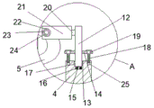
FIG. 2 is a partial enlarged view of the present invention;
fig. 3 is a structural plan view of the rubber ring.
In the figure: 1-phase detector, 2-insulating shell, 3-handle, 4-fixing piece, 5-cooling spiral pipe, 6-spring plate, 7-connecting plate, 8-spring I, 9-water inlet, 10-valve, 11-screw I, 12-supporting rod, 13-sliding block, 14-connecting seat, 15-lower pressing block, 16-spring II, 17-sliding groove, 18-bolt, 19-bearing, 20-rotating shaft, 21-rubber ring, 22-round hole, 23-nut, 24-screw II, 25-threaded hole.
Detailed Description
The technical solutions in the embodiments of the present invention will be described clearly and completely with reference to the accompanying drawings in the embodiments of the present invention, and it is obvious that the described embodiments are only some embodiments of the present invention, not all embodiments. Based on the embodiments in the present invention, all other embodiments obtained by a person skilled in the art without creative work belong to the protection scope of the present invention.
Please refer to fig. 1-3, the present invention provides a technical solution: a nuclear phase reactor with a built-in circulating water cooling device comprises an insulating shell 2, the right side surface of the insulating shell 2 penetrates through and is fixedly connected with a nuclear phase reactor 1, a connecting plate 7 is fixedly arranged between the insulating shell 2 and the nuclear phase reactor 1, the left end of the insulating shell 2 is fixedly connected with a fixing part 4 through a screw I11, the left end surface of the connecting plate 7 is fixedly connected with one end of a spring I8, the other end of the spring I8 is fixedly connected with the right end surface of a spring plate 6, the left end surface of the spring plate 6 is provided with a groove and is clamped with the right end surface of a cooling spiral pipe 5, the left end surface of the nuclear phase reactor 1 is fixedly connected with a handle 3, the left end of the fixing part 4 is movably sleeved with the cooling spiral pipe 5, the left end surface of the fixing part 4 is provided with a threaded hole 25, the inner diameter of the cooling spiral pipe 5 is larger than the diameter of the nuclear phase reactor, a valve 10 is fixedly arranged at the water inlet 9, when the cooling spiral pipe 5 is arranged inside the insulating shell 2, the right end face of the cooling spiral pipe can extrude the spring plate 6, the threaded hole 25 is in threaded connection with a bolt 18, the left end face of the fixing piece 4 is provided with a sliding groove 17, the sliding groove 17 is in sliding arrangement with a sliding block 13, the sliding block 13 is fixedly arranged on the lower end side face of the supporting rod 12, the bottom face of the supporting rod 12 and the upper end face of a lower pressing block 15 are mutually extruded, the lower end face of the lower pressing block 15 is fixedly connected with the upper end of a spring II 16, the lower end of the spring II 16 is fixedly arranged on the bottom face of a groove on the left side face of the fixing piece 4, the middle position of the side face of the supporting rod 12 is fixedly connected with a connecting seat 14, a bearing 19 is fixedly embedded inside the connecting seat 14, the bearing 19 is fixedly sleeved with the bolt 18, the other end and the rubber circle 21 fixed connection of pivot 20, rubber circle 21 is the ring form that does not close, and rubber circle 21 is fixed to be overlapped on cooling spiral pipe 5, and rubber circle 21 has seted up round hole 22 at the opening part, the fixed nut 23 that inlays of one end of round hole 22, and the other end of round hole 22 runs through and swing joint has screw II 24.
The working principle is as follows: firstly, the cooling spiral pipe 5 is taken out from the insulating shell 2 to be filled with water, firstly, a screw i1 is loosened, the fixing piece 4 and the cooling spiral pipe 5 are taken out, then, the valve 10 is communicated and opened, cold water is filled into the whole cooling spiral pipe 5 from the water inlet 9, because of the special shape of the cooling spiral pipe 5, when the cooling spiral pipe 5 is sleeved into the fixing piece 4 each time, the rubber ring 21 is opposite to different positions of the cooling spiral pipe 5, if the cooling spiral pipe 5 takes the rubber ring 21, people need to find out the correct angle for placing the cooling spiral pipe 5, the trouble and the time are very troublesome and time-consuming, so the rubber ring 21 can rotate and move up and down, the rubber ring 21 can be easily fixed and sleeved on the surface of the cooling spiral pipe 5 no matter how the cooling spiral pipe 5 is placed, firstly, the bolt 18 on the connecting seat 14 is loosened, and the connecting rod, then the screw II 24 on the rubber ring 21 is taken down, the position of the rubber ring 21 is adjusted by rotating the rotating shaft 20 and adjusting the height of the connecting rod 12, then the rubber ring 21 is sleeved on the cooling spiral pipe 5, then the screw II 24 is fixed in the nut 23 in the round hole 22, then the bolt 18 is screwed, the connecting rod 12 is fixed, the bolt 18 can drive the connecting seat 14 and the connecting rod 12 to move downwards together in the screwing process until the bolt is not moved, the connecting rod 12 moves up and down in the fixing part 4 through the sliding block 13 on the side surface of the lower end of the connecting rod 12 and the sliding groove 17 in the fixing part 4, the extruding block 15 and the spring II 16 on the lower end of the connecting rod 12 can extrude in the downward moving process, after the cooling spiral pipe 5 is fixed in the fixing part 4, the whole body is arranged in the insulating shell 2, the cooling spiral pipe 5 sleeves the nuclear phase device 1 in the inner diameter, the right end surface of the cooling spiral pipe 5, and extrude spring plate 6, reuse screw I11 is together fixed mounting 4 and insulating casing 1, utilizes cooling spiral pipe 5 can cool off the heat dissipation to nuclear phase ware, improves work efficiency, utilizes portable position and convenient operation's rubber circle 21 to carry on spacingly to cooling spiral pipe 5, and it is all very convenient to dismantle with fixed, has made things convenient for our water changing operation to cooling spiral pipe 5 greatly, and above is exactly this utility model's theory of operation.
Although embodiments of the present invention have been shown and described, it will be appreciated by those skilled in the art that changes, modifications, substitutions and alterations can be made in these embodiments without departing from the principles and spirit of the invention, the scope of which is defined in the appended claims and their equivalents.
Claims (3)
1. A nuclear phase reactor with a built-in circulating water cooling device comprises an insulating shell (2), wherein the right side face of the insulating shell (2) penetrates through and is fixedly connected with a nuclear phase reactor (1), a connecting plate (7) is fixedly arranged between the insulating shell (2) and the nuclear phase reactor (1), the left end of the insulating shell (2) is fixedly connected with a fixing piece (4) through a screw I (11), the left end face of the nuclear phase reactor (1) is fixedly connected with a handle (3), the left end of the fixing piece (4) is movably sleeved with a cooling spiral pipe (5), the left end face of the fixing piece (4) is provided with a threaded hole (25), the threaded hole (25) is in threaded connection with a bolt (18), the left end face of the fixing piece (4) is provided with a sliding groove (17), the sliding groove (17) and a sliding block (13) are arranged in a sliding mode, the sliding block (13) is fixedly arranged on the, the bottom surface of bracing piece (12) extrudees each other with the up end of briquetting (15) down, the lower terminal surface of briquetting (15) and the upper end fixed connection of spring II (16) down, the fixed recess bottom surface that sets up at mounting (4) left surface of lower extreme of spring II (16), bracing piece (12) are at the intermediate position fixedly connected with connecting seat (14) of side, the inside fixed the inlaying of connecting seat (14) has bearing (19), bearing (19) and bolt (18) fixed cup joint, bracing piece (12) are facing the position of nuclear phase ware (1) and the one end swing joint of pivot (20), the other end and rubber circle (21) fixed connection of pivot (20), rubber circle (21) are the unclosed ring form, and rubber circle (21) fixed sleeve is on cooling spiral pipe (5), and rubber circle (21) have seted up round hole (22) at the opening part, and a nut (23) is fixedly embedded at one end of the round hole (22), and the other end of the round hole (22) penetrates through and is movably connected with a screw II (24).
2. The phase reactor of a built-in circulating water cooling device according to claim 1, characterized in that: the left end face of connecting plate (7) and the one end fixed connection of spring I (8), the other end fixed connection of spring I (8) is at the right-hand member face of spring board (6), the left end face of spring board (6) is provided with the recess, and with the right-hand member face joint of cooling spiral pipe (5).
3. The phase reactor of a built-in circulating water cooling device according to claim 1, characterized in that: the inner diameter of the cooling spiral pipe (5) is larger than the diameter of the nuclear phase device (1), the right end of the cooling spiral pipe (5) is provided with a water inlet (9), a valve (10) is fixedly arranged at the water inlet (9), and when the cooling spiral pipe (5) is installed inside the insulating shell (2), the right end face of the cooling spiral pipe extrudes the spring plate (6).
Priority Applications (1)
| Application Number | Priority Date | Filing Date | Title |
|---|---|---|---|
| CN202022460210.2U CN213517337U (en) | 2020-10-29 | 2020-10-29 | Nuclear phase device with built-in circulating water cooling device |
Applications Claiming Priority (1)
| Application Number | Priority Date | Filing Date | Title |
|---|---|---|---|
| CN202022460210.2U CN213517337U (en) | 2020-10-29 | 2020-10-29 | Nuclear phase device with built-in circulating water cooling device |
Publications (1)
| Publication Number | Publication Date |
|---|---|
| CN213517337U true CN213517337U (en) | 2021-06-22 |
Family
ID=76414122
Family Applications (1)
| Application Number | Title | Priority Date | Filing Date |
|---|---|---|---|
| CN202022460210.2U Expired - Fee Related CN213517337U (en) | 2020-10-29 | 2020-10-29 | Nuclear phase device with built-in circulating water cooling device |
Country Status (1)
| Country | Link |
|---|---|
| CN (1) | CN213517337U (en) |
Cited By (1)
| Publication number | Priority date | Publication date | Assignee | Title |
|---|---|---|---|---|
| CN117490662A (en) * | 2023-11-09 | 2024-02-02 | 广东海洋大学 | Automatic warm salt profile observation system based on offshore fixed platform |
-
2020
- 2020-10-29 CN CN202022460210.2U patent/CN213517337U/en not_active Expired - Fee Related
Cited By (1)
| Publication number | Priority date | Publication date | Assignee | Title |
|---|---|---|---|---|
| CN117490662A (en) * | 2023-11-09 | 2024-02-02 | 广东海洋大学 | Automatic warm salt profile observation system based on offshore fixed platform |
Similar Documents
| Publication | Publication Date | Title |
|---|---|---|
| CN211260038U (en) | Industrial robot pump body is with removing base | |
| CN207334518U (en) | A kind of LED light frame of installation easy to disassemble | |
| CN108390626A (en) | a photovoltaic panel | |
| CN111486356A (en) | L ED lamp for solar outdoor camping | |
| CN212676446U (en) | Assembly structure of small-size 5G basic station | |
| CN212807287U (en) | Environmental noise monitoring device | |
| CN216312998U (en) | Rotatory photovoltaic support of intelligence that high strength and sensitivity are high | |
| CN210350555U (en) | Cylindrical power distribution cabinet with good wind resistance | |
| CN210388397U (en) | Multifunctional precision clamp for numerical control machining | |
| CN212178681U (en) | LED street lamp | |
| CN222598604U (en) | A closed geothermal heat exchange device | |
| CN212231359U (en) | But quick assembly disassembly solar cell panel's photovoltaic support | |
| CN212020537U (en) | Positioning device with adjustable PPR pipeline | |
| CN220806091U (en) | Wind power tower body pipe fitting welding tool | |
| CN220516924U (en) | Pipeline cutting equipment for electric power construction | |
| CN217282876U (en) | Solar power generation waste heat utilization device | |
| CN211239927U (en) | Self-rotating all-dimensional monitoring device for distributed power generation | |
| CN213646391U (en) | Power battery cover plate welding equipment | |
| CN217508326U (en) | Based on GPS locator mounting structure for charging | |
| CN219611683U (en) | Maintainable photovoltaic solar tracker | |
| CN223790347U (en) | A type of combined sleeve | |
| CN220062156U (en) | Air source heat pump heat radiation structure | |
| CN216403528U (en) | Escalator fault diagnosis locator | |
| CN213730551U (en) | Lathe fixing clamp for metal shell production | |
| CN210326259U (en) | Electrode flange capable of avoiding pollution of electrode core column |
Legal Events
| Date | Code | Title | Description |
|---|---|---|---|
| GR01 | Patent grant | ||
| GR01 | Patent grant | ||
| CF01 | Termination of patent right due to non-payment of annual fee |
Granted publication date: 20210622 |
|
| CF01 | Termination of patent right due to non-payment of annual fee |