CN213474429U - Powdery and granular material elevator - Google Patents
Powdery and granular material elevator Download PDFInfo
- Publication number
- CN213474429U CN213474429U CN202022067227.1U CN202022067227U CN213474429U CN 213474429 U CN213474429 U CN 213474429U CN 202022067227 U CN202022067227 U CN 202022067227U CN 213474429 U CN213474429 U CN 213474429U
- Authority
- CN
- China
- Prior art keywords
- fixedly connected
- casing
- motor
- chain
- powdery
- Prior art date
- Legal status (The legal status is an assumption and is not a legal conclusion. Google has not performed a legal analysis and makes no representation as to the accuracy of the status listed.)
- Active
Links
- 239000008187 granular material Substances 0.000 title claims abstract description 21
- 239000000463 material Substances 0.000 claims abstract description 35
- 235000017166 Bambusa arundinacea Nutrition 0.000 claims abstract description 10
- 235000017491 Bambusa tulda Nutrition 0.000 claims abstract description 10
- 241001330002 Bambuseae Species 0.000 claims abstract description 10
- 235000015334 Phyllostachys viridis Nutrition 0.000 claims abstract description 10
- 239000011425 bamboo Substances 0.000 claims abstract description 10
- 230000008878 coupling Effects 0.000 claims description 7
- 238000010168 coupling process Methods 0.000 claims description 7
- 238000005859 coupling reaction Methods 0.000 claims description 7
- 238000007599 discharging Methods 0.000 claims description 5
- 125000004122 cyclic group Chemical group 0.000 description 3
- 230000009286 beneficial effect Effects 0.000 description 1
- 230000005540 biological transmission Effects 0.000 description 1
- 239000004568 cement Substances 0.000 description 1
- 239000003245 coal Substances 0.000 description 1
- 230000007547 defect Effects 0.000 description 1
- 230000003028 elevating effect Effects 0.000 description 1
- 230000004048 modification Effects 0.000 description 1
- 238000012986 modification Methods 0.000 description 1
- 230000001737 promoting effect Effects 0.000 description 1
- 238000004064 recycling Methods 0.000 description 1
- 238000000926 separation method Methods 0.000 description 1
Images


Landscapes
- Filling Or Emptying Of Bunkers, Hoppers, And Tanks (AREA)
Abstract
The utility model discloses a likepowder, granule material lifting machine, which comprises a housing, the inner wall of casing rotates and is connected with the sprocket, the inside fixedly connected with guide rail of casing, the chain has been cup jointed to the surface of sprocket, the surface of chain rotates and is connected with first spliced pole, and the one end and the guide rail sliding connection of first spliced pole, the surface of chain rotates and is connected with the second spliced pole, and the second spliced pole rotates with first spliced pole to be connected, the one end fixedly connected with hopper of second spliced pole, one side fixedly connected with ejection of compact platform of casing, and ejection of compact platform runs through the casing and extends to inside, the opposite side fixedly connected with support of casing, the first motor of top fixedly connected with of support. The utility model discloses in, send the material to the eminence from the low through the chain that sets up, sprocket, through the broken convenient hopper transportation of likepowder, the granule material that the broken section of thick bamboo that sets up will easily harden.
Description
Technical Field
The utility model relates to a material transport field especially relates to a likepowder, granule material lifting machine.
Background
A continuous conveyor for vertically elevating materials by means of a series of hoppers uniformly secured to and on an endless traction member. The vertical conveying of powdery, granular and small-block bulk materials with small grinding and suction properties, such as grains, coal, cement, crushed ore and the like, the hopper scoops up the materials from the storage below, the materials are lifted to the top along with a conveying belt or a chain and turned downwards after bypassing a top wheel, the elevator pours the materials into a receiving groove, the elevator is suitable for lifting from a low position to a high position, and the supplied materials are conveyed upwards through automatic continuous operation of the machine after being put into the hopper through a vibrating table.
The existing elevator lacks a low-speed crushing device when transporting powdery and granular materials, the powdery and granular materials are easy to harden after entering the interior of the elevator, a hopper is difficult to scoop up material transportation, and the hardened materials are easy to block a collecting pipe when collecting and recycling the materials.
SUMMERY OF THE UTILITY MODEL
The utility model aims at solving the defects existing in the prior art and providing a powdery and granular material hoister.
In order to achieve the above purpose, the utility model adopts the following technical scheme: a powdery and granular material hoister comprises a casing, wherein a chain wheel is rotatably connected to the inner wall of the casing, a guide rail is fixedly connected to the inside of the casing, a chain is sleeved on the outer surface of the chain wheel, a first connecting column is rotatably connected to the outer surface of the chain, one end of the first connecting column is slidably connected with the guide rail, a second connecting column is rotatably connected to the outer surface of the chain and is rotatably connected with the first connecting column, a hopper is fixedly connected to one end of the second connecting column, a discharge table is fixedly connected to one side of the casing and penetrates through the casing and extends into the casing, a support is fixedly connected to the other side of the casing, a first motor is fixedly connected to the top end of the support, a feeding table is fixedly connected to the edge of the bottom end of the casing, a supporting table is fixedly connected to the bottom end of the feeding table, and a material receiving box is, the bottom fixedly connected with collecting pipe of casing, the top fixedly connected with motor frame of brace table, the top fixedly connected with second motor of motor frame, the drive end fixedly connected with shaft coupling of second motor, the broken section of thick bamboo of fixedly connected with is rotated to one side of shaft coupling, and broken section of thick bamboo runs through the casing and extends to the inside of casing.
As a further description of the above technical solution:
the driving end of the first motor is fixedly connected with a first belt wheel, the first belt wheel is sleeved with a belt, the inner wall of the shell is rotatably connected with a second belt wheel, and the second belt wheel is fixedly connected with the chain wheel.
As a further description of the above technical solution:
an observation window is fixedly connected to the outer surface of the shell.
As a further description of the above technical solution:
the inner surface of the collecting pipe is fixedly connected with an electromagnetic valve.
As a further description of the above technical solution:
the outer surface of the crushing barrel is provided with a bulge.
As a further description of the above technical solution:
the second motor is a servo motor.
The utility model discloses following beneficial effect has: when using this likepowder, granule material lifting machine, can realize promoting the material from low to high automatically through sprocket, guide rail, first motor, the chain that sets up, first motor drive end rotates and drives first band pulley and rotate and then drive the sprocket and rotate. Finally drive the chain and remove and promote the material with hopper cyclic motion, the broken section of thick bamboo that bottom of the case set up simultaneously can be with the material that hardens through the rotatory broken separation of second motor at this moment the hopper scoops up the material easily.
Drawings
Fig. 1 is a sectional view of a powdery and granular material elevator provided by the utility model;
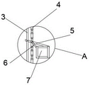
FIG. 2 is an enlarged view of the A position of the powdery and granular material elevator provided by the present invention;
fig. 3 is a schematic view of the belt transmission of the lifter for powdery and granular materials according to the present invention.
Illustration of the drawings:
1. a housing; 2. a sprocket; 3. a guide rail; 4. a chain; 5. a first connecting column; 6. a second connecting column; 7. a hopper; 8. a discharging table; 9. a support; 10. a first motor; 11. a first pulley; 12. a belt; 13. a second pulley; 14. a lookout window; 15. a feeding table; 16. a support table; 17. a material receiving box; 18. a collection pipe; 19. an electromagnetic valve; 20. a motor frame; 21. a second motor; 22. a coupling; 23. and (5) crushing the barrel.
Detailed Description
The technical solutions in the embodiments of the present invention will be described clearly and completely with reference to the accompanying drawings in the embodiments of the present invention, and it is obvious that the described embodiments are only some embodiments of the present invention, not all embodiments. Based on the embodiments in the present invention, all other embodiments obtained by a person skilled in the art without creative work belong to the protection scope of the present invention.
In the description of the present invention, it should be noted that the terms "center", "upper", "lower", "left", "right", "vertical", "horizontal", "inner", "outer", and the like indicate orientations or positional relationships based on the orientations or positional relationships shown in the drawings, and are only for convenience of description and simplification of description, but do not indicate or imply that the device or element referred to must have a specific orientation, be constructed and operated in a specific orientation, and thus, should not be construed as limiting the present invention; the terms "first," "second," and "third" are used for descriptive purposes only and are not to be construed as indicating or implying relative importance, and furthermore, unless otherwise explicitly stated or limited, the terms "mounted," "connected," and "connected" are to be construed broadly and may be, for example, fixedly connected, detachably connected, or integrally connected; can be mechanically or electrically connected; they may be connected directly or indirectly through intervening media, or they may be interconnected between two elements. The specific meaning of the above terms in the present invention can be understood in specific cases to those skilled in the art.
Referring to fig. 1-3, the present invention provides an embodiment: a powdery and granular material elevator comprises a machine shell 1, wherein the inner wall of the machine shell 1 is rotatably connected with a chain wheel 2, the interior of the machine shell 1 is fixedly connected with a guide rail 3, the guide rail 3 and a first connecting column 5 tightly press a chain 4 to enable the chain 4 to be always meshed with the chain wheel 2, the outer surface of the chain wheel 2 is sleeved with the chain 4, the outer surface of the chain 4 is rotatably connected with the first connecting column 5, one end of the first connecting column 5 is slidably connected with the guide rail 3, the outer surface of the chain 4 is rotatably connected with a second connecting column 6, the second connecting column 6 is rotatably connected with the first connecting column 5, one end of the second connecting column 6 is fixedly connected with a hopper 7, one side of the machine shell 1 is fixedly connected with a discharging table 8, the discharging table 8 penetrates through the machine shell 1 and extends to the interior, the other side of the machine shell 1 is fixedly connected with a support 9, the top end of the support 9 is fixedly connected with a first motor 10, thereby make and connect hopper 7 in 4 one sides of chain can the cyclic motion, the bottom of casing 1 is close to edge fixedly connected with feed table 15, the bottom fixedly connected with brace table 16 of feed table 15, the top fixedly connected with of brace table 16 receives workbin 17, the bottom fixedly connected with collecting pipe 18 of casing 1, the top fixedly connected with motor frame 20 of brace table 16, the top fixedly connected with second motor 21 of motor frame 20, the drive end fixedly connected with shaft coupling 22 of second motor 21, the broken section of thick bamboo 23 of fixedly connected with is rotated to one side of shaft coupling 22, and broken section of thick bamboo 23 runs through casing 1 and extends to the inside of casing 1, broken material that the broken section of thick bamboo 23 will harden makes things convenient for hopper 7 to transport, can not block up collecting pipe 18 when retrieving the residual material yet simultaneously.
The driving end of the first motor 10 is fixedly connected with a first belt wheel 11, the first belt wheel 11 is sleeved with a belt 12, the inner wall of the machine shell 1 is rotatably connected with a second belt wheel 13, the second belt wheel 13 is fixedly connected with the chain wheel 2, and the chain wheel 2 is driven by the linkage of the first motor 10, the first belt wheel 11 and the second belt wheel 13 to enable the hopper 7 to scoop up materials according to the rotating speed of the first motor 10 so as to convey the materials.
An observation window 14 is fixedly connected to the outer surface of the casing 1, the observation window 14 is transparent, and an operator can observe the internal condition of the elevator through the observation window 14 to judge the opening and closing of the second motor 21.
The inner surface of the collecting pipe 18 is fixedly connected with an electromagnetic valve 19, so that residual materials can be conveniently recycled.
The outer surface of the crushing barrel 23 is provided with a bulge, and the bulge can crush hardened materials and bring convenience to the hopper 7 to transport the materials.
The second motor 21 is a servo motor, and is more smoothly opened and closed.
The working principle is as follows: during the transportation material, first motor 10 is opened, the rotatory fixed connection's of first motor 10 drive end first band pulley 11 is followed rotatoryly, it is rotatory to drive second band pulley 13 through belt 12 this moment, second band pulley 13 is rotatory to drive fixed connection's sprocket 2 rotatory, sprocket 2 is rotatory to be rotatory the chain 4 that cup joints in the hopper 7 begin the cyclic motion and to scoop up the material that gets into from feed table 15 and carry to ejection of compact platform 8, the staff observes the pay-off condition through observation window 14, it is unsmooth to open second motor 21 through broken section of thick bamboo 23 to discover to get into inside likepowder of lifting machine or granule material hardening hopper 7 transportation, after the pay-off, open solenoid valve 19 and carry the surplus material to collecting box 17, if there is the material that hardens to block up to open the broken material of second motor 21.
Finally, it should be noted that: although the present invention has been described in detail with reference to the foregoing embodiments, it will be apparent to those skilled in the art that modifications and variations can be made in the embodiments or in part of the technical features of the embodiments without departing from the spirit and the scope of the invention.
Claims (6)
1. The utility model provides a powdery, granule material lifting machine, includes casing (1), its characterized in that: the inner wall of the casing (1) is rotatably connected with a chain wheel (2), the interior of the casing (1) is fixedly connected with a guide rail (3), the outer surface of the chain wheel (2) is sleeved with a chain (4), the outer surface of the chain (4) is rotatably connected with a first connecting column (5), one end of the first connecting column (5) is slidably connected with the guide rail (3), the outer surface of the chain (4) is rotatably connected with a second connecting column (6), the second connecting column (6) is rotatably connected with the first connecting column (5), one end of the second connecting column (6) is fixedly connected with a hopper (7), one side of the casing (1) is fixedly connected with a discharging table (8), the discharging table (8) penetrates through the casing (1) and extends to the interior, the other side of the casing (1) is fixedly connected with a support (9), the top end of the support (9) is fixedly connected with a first motor (10), the bottom of casing (1) is close to edge fixedly connected with feed table (15), the bottom fixedly connected with brace table (16) of feed table (15), the top fixedly connected with of brace table (16) receives workbin (17), the bottom fixedly connected with collecting pipe (18) of casing (1), the top fixedly connected with motor frame (20) of brace table (16), the top fixedly connected with second motor (21) of motor frame (20), the drive end fixedly connected with shaft coupling (22) of second motor (21), one side of shaft coupling (22) is rotated the broken section of thick bamboo (23) of fixedly connected with, and broken section of thick bamboo (23) run through casing (1) and extend to the inside of casing (1).
2. The powdery and granular material elevator as set forth in claim 1, characterized in that: the driving end of the first motor (10) is fixedly connected with a first belt wheel (11), the first belt wheel (11) is sleeved with a belt (12), the inner wall of the machine shell (1) is rotatably connected with a second belt wheel (13), and the second belt wheel (13) is fixedly connected with the chain wheel (2).
3. The powdery and granular material elevator as set forth in claim 1, characterized in that: the outer surface of the shell (1) is fixedly connected with an observation window (14).
4. The powdery and granular material elevator as set forth in claim 1, characterized in that: the inner surface of the collecting pipe (18) is fixedly connected with an electromagnetic valve (19).
5. The powdery and granular material elevator as set forth in claim 1, characterized in that: the outer surface of the crushing barrel (23) is provided with a bulge.
6. The powdery and granular material elevator as set forth in claim 1, characterized in that: the second motor (21) is a servo motor.
Priority Applications (1)
| Application Number | Priority Date | Filing Date | Title |
|---|---|---|---|
| CN202022067227.1U CN213474429U (en) | 2020-09-21 | 2020-09-21 | Powdery and granular material elevator |
Applications Claiming Priority (1)
| Application Number | Priority Date | Filing Date | Title |
|---|---|---|---|
| CN202022067227.1U CN213474429U (en) | 2020-09-21 | 2020-09-21 | Powdery and granular material elevator |
Publications (1)
| Publication Number | Publication Date |
|---|---|
| CN213474429U true CN213474429U (en) | 2021-06-18 |
Family
ID=76363525
Family Applications (1)
| Application Number | Title | Priority Date | Filing Date |
|---|---|---|---|
| CN202022067227.1U Active CN213474429U (en) | 2020-09-21 | 2020-09-21 | Powdery and granular material elevator |
Country Status (1)
| Country | Link |
|---|---|
| CN (1) | CN213474429U (en) |
Cited By (1)
| Publication number | Priority date | Publication date | Assignee | Title |
|---|---|---|---|---|
| CN113895870A (en) * | 2021-11-23 | 2022-01-07 | 安徽百特机电工程有限公司 | Environment-friendly bucket elevator |
-
2020
- 2020-09-21 CN CN202022067227.1U patent/CN213474429U/en active Active
Cited By (1)
| Publication number | Priority date | Publication date | Assignee | Title |
|---|---|---|---|---|
| CN113895870A (en) * | 2021-11-23 | 2022-01-07 | 安徽百特机电工程有限公司 | Environment-friendly bucket elevator |
Similar Documents
| Publication | Publication Date | Title |
|---|---|---|
| CN112960410A (en) | Multifunctional automatic feeding equipment | |
| CN107954163A (en) | A kind of automatic material transport system | |
| CN205561996U (en) | Automatic change that material sieves and weighing system | |
| CN213706751U (en) | Vertical material lifting equipment | |
| CN211686656U (en) | A automatic feeding device for TPE batching | |
| CN115520672B (en) | Closed feeding device | |
| CN210943568U (en) | A screw conveyor for solid material is carried | |
| CN214933157U (en) | Multi-point discharging chain bucket conveyor for ore grinding | |
| CN212330634U (en) | Automatic polishing system for nails | |
| CN211109388U (en) | Bucket elevator for feed production | |
| CN216661786U (en) | Ton package discharge apparatus | |
| CN213263068U (en) | Quantitative conveying device for agricultural transportation | |
| CN221115372U (en) | Mining is with removing hopper | |
| CN208813538U (en) | A kind of seed packaging scale with elevator | |
| CN222294106U (en) | Automatic slag removing machine | |
| CN213651011U (en) | Automatic change material loading lifting machine | |
| CN222409855U (en) | Material conveying elevator | |
| CN207311873U (en) | A kind of feed packing that can filter out irony claims | |
| CN218905864U (en) | Concrete mixer feed arrangement | |
| CN223765603U (en) | A feeding component and a dust-free feeding device | |
| CN223162794U (en) | Ton package material station of throwing | |
| CN216375079U (en) | A unloader for concrete subtracts glue agent | |
| CN212702205U (en) | Waste crushing and conveying integrated device | |
| CN219729870U (en) | Powder conveying device with metering device | |
| CN224076313U (en) | Plate chain bucket type multifunctional elevator |
Legal Events
| Date | Code | Title | Description |
|---|---|---|---|
| GR01 | Patent grant | ||
| GR01 | Patent grant |