Transformer joint processing apparatus that generates heat
Technical Field
The utility model relates to a transformer bushing overhauls equipment technical field, especially a transformer connects processing apparatus that generates heat.
Background
In the running process of the transformer, the heating defect of the sleeve lead joint often occurs, and the safe and stable running of the equipment is seriously influenced. Through the discovery of disintegrating to overhaul, the reason that sleeve pipe pin joint generates heat is mostly that cable pin joint external screw thread is not hard up with conductive head female connection department, and the contact surface oxidation, silvered film drop. The conventional maintenance method is to clean the surface of the thread by using absolute ethyl alcohol, remove an oxide layer and then coat conductive paste on the surface of the thread, but after the transformer bushing runs for a period of time, the conductive paste can be hardened and pulverized to cause the contact surface of a lead connector to form a gap, so that connection is loosened, contact resistance is increased, the defect of heating occurs again, repeated power failure maintenance is caused, and the problem cannot be thoroughly solved.
Therefore, a technical scheme is needed at present to solve the technical problem that the casing lead joint is damaged due to heating caused by hardening and pulverization of the conductive paste after long-term use in the prior art that the casing lead joint is repaired by brushing the conductive paste.
SUMMERY OF THE UTILITY MODEL
The invention of the utility model aims to: the heating processing device for the transformer joint is provided, aiming at the technical problems that in the prior art, the casing lead joint is repaired by brushing conductive paste, and after long-term use, the conductive paste is easy to harden and pulverize, so that the casing lead joint is heated and damaged.
In order to realize the purpose, the utility model discloses a technical scheme be:
the utility model provides a transformer joint processing apparatus that generates heat, includes that power and brush plate, the power with the brush plate is electric to be connected, the brush plate is the conducting material structure, the power is used for being connected with sleeve pipe pin joint electricity.
The utility model relates to a transformer joint processing apparatus that generates heat, use the wire to plate the board with the brush and be connected with the anodal electricity of power, use the wire to link to each other sleeve pipe pin joint and power negative pole, again with the brush plate stretch into the electrolyte that has silver ion, after dipping in and getting electrolyte, brush sleeve pipe pin joint with electrolyte through the brush plate on, electrolytic reaction makes metallic silver adhere to sleeve pipe pin joint on, form silver-plated layer again on sleeve pipe pin joint, make sleeve pipe pin joint resume good electric conductive property, avoid appearing the condition of the damage of generating heat.
As the preferred proposal of the utility model, the brush plating plate is provided with a fiber sleeve. The fiber sleeve can accumulate a large amount of electrolyte, and meanwhile, the fiber sleeve can be in closer contact with the sleeve lead connector, so that the brush plating efficiency is improved, and the plating layer is more uniform.
As the preferred proposal of the utility model, the brush plating plate is arranged into an arc surface shape. The brush plating plate is arranged to be arc-surface-shaped and matched with the sleeve lead joint, so that the brush plating plate is more tightly attached to the sleeve lead joint, on one hand, the electrolyte is more uniformly distributed on the sleeve lead joint in the brush plating process, and on the other hand, the brush plating efficiency is improved.
As the preferred scheme of the utility model, be equipped with a plurality of reservoir on the brush plating board, the reservoir sets up concave surface one side of brush plating board. Make the brush plate dip in and get electrolyte after, electrolyte can remain more on the brush plate, reduces the brush plate and makes a round trip to dip in and get the electrolyte number of times, improves the efficiency that the brush was plated, and the reservoir also can increase the static friction power of fibre cover and brush plate simultaneously, avoids plating the in-process fibre cover at the brush and drops the brush plate.
As the preferred scheme of the utility model, a plurality of the reservoir is followed the length direction of brush plating board evenly sets up. The electrolyte is more uniformly distributed on the brush plating plate, so that the electrolyte is more uniformly distributed on the sleeve lead connector in the brush plating process, and the brush plating efficiency is higher.
As the preferred scheme of the utility model, the depth of the liquid storage tank is 1-3 mm. The too big meeting of liquid storage tank depth can lead to brush to plate board and sleeve pipe pin joint laminating inseparable, and the reservoir depth degree undersize is unfavorable for electrolyte to be retained on the brush plate board, sets up the liquid storage tank depth degree and can ensure to plate the prerequisite that the board has sufficient stock solution ability with the brush between 1-3mm, also can with sleeve pipe pin joint between the laminating inseparable.
As the preferred proposal of the utility model, the brush plating plate is connected with a handle, and the handle is provided with an insulating layer. The brush plating operation is conveniently carried out by holding the handle by an operator, and the operation convenience of the brush plating plate is improved.
As the preferred scheme of the utility model, the insulating layer is the rubber material structure. The rubber material not only has good insulating property, but also has simple manufacturing process and low cost, and is beneficial to batch manufacturing.
As the preferred scheme of the utility model, electrically conductive material is the metal. The metal material not only has good conductive performance, can realize the conductive effect, and the metal generally has good processing performance, can be made into various required shapes, and the metal material hardness is great, is difficult for appearing warping and damaging in long-term use.
As a preferable embodiment of the present invention, the metal is stainless steel. The stainless steel has good conductivity and good processability, and simultaneously has the corrosion resistance, so that the possibility of rusting of the brush-plated plate can be reduced and the service life of the brush-plated plate can be prolonged under the condition that water participates in the brush plating process.
To sum up, owing to adopted above-mentioned technical scheme, the beneficial effects of the utility model are that:
through brush plating board and sleeve pipe lead joint continuous with the positive negative pole of power respectively, dip in the brush plating board and get the electrolyte that has silver ion after, with electrolyte brush plating on sleeve pipe lead joint to make silver ion adhere to sleeve pipe lead joint, form silver-plated layer again on sleeve pipe lead joint, make sleeve pipe lead joint resume good electric conductive property, avoid the condition of leaving heat damage.
Drawings
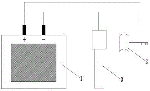
Fig. 1 is a schematic structural view of a transformer joint heat treatment device of the present invention;
FIG. 2 is a schematic cross-sectional view of a brush-plated board according to the present invention;
FIG. 3 is a schematic structural view of the concave side of the brush plating plate according to the present invention;
the labels in the figure are: 1-power supply, 2-brush plating board, 21-liquid storage tank, 3-sleeve lead connector, 4-fiber sleeve and 5-handle.
Detailed Description
The present invention will be described in detail with reference to the accompanying drawings.
In order to make the objects, technical solutions and advantages of the present invention more clearly understood, the present invention is further described in detail below with reference to the accompanying drawings and embodiments. It should be understood that the specific embodiments described herein are for purposes of illustration only and are not intended to limit the invention.
Example 1
As shown in fig. 1-3, a transformer joint heat treatment device includes a power supply 1 and a brush plating plate 2, the power supply 1 is electrically connected to the brush plating plate 2, the brush plating plate 2 is a conductive material structural member, the power supply 1 is used for being electrically connected to a bushing lead connector 3, preferably, the conductive material is metal, the metal material has good conductivity and can realize conductive effect, meanwhile, the metal generally has good processability, can be manufactured into various required shapes, and has high hardness, and is not easy to deform and damage in a long-term use process; more preferably, the metal is stainless steel, the stainless steel not only has good conductivity and good processability, but also has the capability of corrosion resistance, and under the condition that water is involved in the brush plating process, the possibility of rusting of the brush plating plate 2 can be reduced, and the service life of the brush plating plate 2 can be prolonged.
Furthermore, the brush plating plate 2 is provided with the fiber sleeve 4, the fiber sleeve 4 can accumulate a large amount of electrolyte, and meanwhile, the fiber sleeve 4 can be in closer contact with the sleeve lead connector 3, so that the brush plating efficiency is improved, and the plating layer is more uniform.
Further, brush plating board 2 sets up to the cambered surface shape, will brush plating board 2 sets up to the cambered surface shape that matches with sleeve pipe pin joint 3 for brush plating board 2 is inseparabler with the 3 laminating of sleeve pipe pin joint, makes the brush plating in-process on the one hand, and electrolyte distributes more evenly on sleeve pipe pin joint 3, and on the other hand has improved the brush plating efficiency.
Furthermore, a plurality of liquid storage tanks 21 are arranged on the brush-plating plate 2, the liquid storage tanks 21 are arranged on one side of the concave surface of the brush-plating plate 2, so that more electrolyte can be left on the brush-plating plate 2 after the brush-plating plate 2 is dipped with the electrolyte, the frequency of the brush-plating plate 2 dipping the electrolyte back and forth is reduced, the brush-plating efficiency is improved, meanwhile, the liquid storage tanks 21 can also increase the static friction force between the fiber sleeve 4 and the brush-plating plate 2, and the fiber sleeve 4 is prevented from falling off the brush-plating plate 2 in the brush-plating process; further, it is a plurality of reservoir 21 follows brush plating board 2's length direction evenly sets up for electrolyte distributes more evenly on brush plating board 2, thereby makes the brush plating in-process, and electrolyte distributes more evenly on sleeve pipe pin joint 3, and the brush plating efficiency is higher, and is specific, reservoir 21's degree of depth is 1-3mm, and reservoir 21 degree of depth too big can lead to brush plating board 2 and sleeve pipe pin joint 3 laminating not inseparable, and reservoir 21 degree of depth undersize is unfavorable for electrolyte to be retained on brush plating board 2, sets up reservoir 21 degree of depth between 1-3mm and can ensure under brush plating board 2 has sufficient stock solution ability's the prerequisite, also can with sleeve pipe pin joint 3 between laminating closely.
Further, even there is handle 5 on the brush plate 2, be equipped with the insulating layer on the handle 5, the operation personnel of being convenient for hold handle 5 and carry out the brush plating operation, have improved the simple operation nature of brush plate 2, wherein the insulating layer is the rubber material structure, and the rubber material not only has good insulating properties, and manufacturing process is simple moreover, and is with low costs, does benefit to batch manufacturing.
The utility model relates to a transformer joint processing apparatus that generates heat, use the wire to plate 2 with the brush and be connected with 1 anodal electricity in power, use the wire to link to each other sleeve pipe pin joint 3 with the power negative pole, again with the brush plate 2 stretch into the electrolyte that has silver ion, after dipping in and getting electrolyte, plate 2 with the brush through the brush and brush sleeve pipe pin joint 3 on with electrolyte, thereby make silver ion adhere to sleeve pipe pin joint 3 on, form silver-plated layer again on sleeve pipe pin joint 3, make sleeve pipe pin joint 3 resume good electric conductive property, avoid appearing the condition of the damage that generates heat.
The above description is only exemplary of the present invention and should not be taken as limiting the scope of the present invention, as any modifications, equivalents, improvements and the like made within the spirit and principles of the present invention are intended to be included within the scope of the present invention.