CN213452643U - Textile machinery supporting device with adjustable gradient - Google Patents
Textile machinery supporting device with adjustable gradient Download PDFInfo
- Publication number
- CN213452643U CN213452643U CN202022340663.1U CN202022340663U CN213452643U CN 213452643 U CN213452643 U CN 213452643U CN 202022340663 U CN202022340663 U CN 202022340663U CN 213452643 U CN213452643 U CN 213452643U
- Authority
- CN
- China
- Prior art keywords
- extension board
- type frame
- articulated
- bolt
- base
- Prior art date
- Legal status (The legal status is an assumption and is not a legal conclusion. Google has not performed a legal analysis and makes no representation as to the accuracy of the status listed.)
- Expired - Fee Related
Links
- 239000004753 textile Substances 0.000 title claims abstract description 20
- 230000000670 limiting effect Effects 0.000 claims description 18
- 238000001125 extrusion Methods 0.000 claims 1
- 238000000034 method Methods 0.000 description 4
- 230000009471 action Effects 0.000 description 3
- 230000008901 benefit Effects 0.000 description 2
- 230000000149 penetrating effect Effects 0.000 description 2
- 230000008569 process Effects 0.000 description 2
- 230000004075 alteration Effects 0.000 description 1
- 230000009286 beneficial effect Effects 0.000 description 1
- 238000010586 diagram Methods 0.000 description 1
- 238000006073 displacement reaction Methods 0.000 description 1
- 230000000694 effects Effects 0.000 description 1
- 238000012986 modification Methods 0.000 description 1
- 230000004048 modification Effects 0.000 description 1
- 238000006467 substitution reaction Methods 0.000 description 1
Images



Landscapes
- Preliminary Treatment Of Fibers (AREA)
Abstract
The utility model relates to a textile machinery especially relates to a textile machinery strutting arrangement of adjustable gradient, and the device can adjust the inclination of support, adapts to different support requirements, effectively solves the problem of proposing among the background art. The improved multifunctional support comprises a base, the fixed first U type frame plate that is equipped with the opening in base upper surface intermediate position, first U type frame plate in vertically be equipped with the extension board, the extension board under the tip articulated through first articulated shaft and first U type frame plate, the extension board cross-section is the rectangle, and the left and right sides border is vertical respectively and is equipped with a plurality of circular through-holes, extension board left and right sides face and base between be equipped with tractive support piece respectively. The operation is simple, the use is convenient, and the device is suitable for various places.
Description
Technical Field
The utility model relates to a textile machinery specifically is a textile machinery strutting arrangement of adjustable gradient.
Background
With the progress of science and technology and the development of society, the living standard of people is continuously improved, and higher requirements are also put forward on textiles. In recent years, the textile industry in China has been rapidly developed, and the rapid development of textile machinery is followed. The existing supporting device of the textile machine can only vertically play a role in supporting, the inclination degree can not be adjusted, and the supporting device needs to be obliquely supported in some places, so that the requirement can not be met, and the use range is not favorably expanded.
SUMMERY OF THE UTILITY MODEL
The utility model provides a not enough to prior art, the utility model provides a textile machinery strutting arrangement of adjustable gradient, the device can adjust the inclination of support, adapts to different support requirements, effectively solves the problem of proposing in the background art.
In order to achieve the above object, the utility model provides a following technical scheme: the utility model provides a textile machinery strutting arrangement of adjustable gradient which characterized in that: the improved multifunctional support comprises a base, the fixed first U type frame plate that is equipped with the opening in base upper surface intermediate position, first U type frame plate in vertically be equipped with the extension board, the extension board under the tip articulated through first articulated shaft and first U type frame plate, the extension board cross-section is the rectangle, and the left and right sides border is vertical respectively and is equipped with a plurality of circular through-holes, extension board left and right sides face and base between be equipped with tractive support piece respectively.
Preferably, tractive support piece including the second U type frame board of locating the extension board left and right sides towards the extension board open-ended, extension board side is arranged in to second U type frame integrated circuit board, and link up a circular through-hole through the bolt around and articulated with the extension board, the end of wearing out of bolt is equipped with first nut, the second U type frame board outside respectively with the branch top fixed connection of slope, the branch bottom is articulated with articulated seat through the second articulated shaft, articulated seat is fixed in the slider upper surface, be equipped with the slideway groove that supplies the slider horizontal slip on the base, twist from top to bottom on the slider and have the spacing bolt.
Preferably, the slide block is of a T-shaped structure, and the slide channel groove is of an inverted T-shaped structure matched with the slide block.
Preferably, the limit bolt vertically runs through the slide block, the bottom surface of the limit bolt is matched with the bottom surface of the slide channel in a squeezing mode, and the limit bolt on the upper side of the slide block is provided with a second nut.
Preferably, the bottom of the limiting bolt is in a pointed shape, and a plurality of arc-shaped grooves which are matched with the pointed end and are arranged left and right are embedded in the bottom surface of the slideway slot.
Preferably, the upper end part of the limiting bolt is provided with a rubber sleeve.
Compared with the prior art, the utility model provides a textile machinery strutting arrangement of adjustable gradient possesses following beneficial effect:
1. the utility model discloses a first U type frame plate in vertical extension board that is equipped with, the extension board under the tip articulated through first articulated shaft and first U type frame plate, the extension board crosscut is personally submitted rectangle, and the left and right sides border is equipped with a plurality of circular through-holes respectively vertical arrangement, extension board left and right sides face and base between be equipped with tractive support piece respectively, during the use, inclination can be adjusted through first articulated shaft to the extension board, tractive support piece can the left and right sides play the effect of auxiliary stay to the extension board respectively, do benefit to the stability of extension board work.
2. The utility model discloses an extension board side is arranged in to second U type frame integrated circuit board, and it is articulated with the extension board to link up a circular through-hole through the bolt around, the end of wearing out of bolt is equipped with first nut, the second U type frame board outside respectively with the branch top fixed connection of slope, the branch bottom is articulated with articulated seat through the second articulated shaft, articulated seat is fixed in the slider upper surface, be equipped with the slide way groove that supplies slider horizontal slip on the base, from top to bottom twist soon on the slider and twist spacing bolt, during the use, can adjust the fixed position of second U type frame board through the cooperation of bolt and circular through-hole, thereby can adjust the holding position of branch, the bottom of branch can be adjusted through the slider and control the position, and spacing through spacing bolt, do benefit to the fastness that branch supported.
3. The utility model discloses a vertical slider setting that runs through of spacing bolt, the bottom surface is crowded to touch the cooperation with the chute bottom surface, and is equipped with the second nut on the spacing bolt of slider upside, during the use, revolves soon spacing bolt downwards for spacing bolt bottom surface and chute bottom surface contact, thereby play limiting displacement, the second nut can prevent that spacing bolt is not hard up.
Drawings
Fig. 1 is a schematic view of the structure of the present invention;
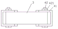
FIG. 2 is a schematic top view of the support plate and the first U-shaped frame plate;
fig. 3 is a right view structural diagram of the slider and the base.
Fig. 4 is an enlarged schematic view of a portion a in fig. 1.
The following are marked in the figure: 1. a base; 11. a chute; 2. a first U-shaped frame plate; 21. a first hinge shaft; 3. a support plate; 31. a circular through hole; 4. pulling the support; 41. a second U-shaped frame plate; 42. a bolt; 421. a first nut; 43. a strut; 44. a second hinge shaft; 45. a hinged seat; 46. a slider; 47. a limit bolt; 48. a second nut.
Detailed Description
The technical solutions in the embodiments of the present invention will be described clearly and completely with reference to the accompanying drawings in the embodiments of the present invention, and it is obvious that the described embodiments are only some embodiments of the present invention, not all embodiments. Based on the embodiments in the present invention, all other embodiments obtained by a person skilled in the art without creative work belong to the protection scope of the present invention.
As shown in fig. 1 to 4, a textile machine supporting device with adjustable inclination comprises a base 1, a first U-shaped frame plate 2 with an upper opening is fixedly arranged at the middle position of the upper surface of the base 1, a support plate 3 is vertically arranged in the first U-shaped frame plate 2, the lower end of the support plate 3 is hinged to the first U-shaped frame plate 2 through a first hinge shaft 21, the cross section of the support plate 3 is rectangular, a plurality of circular through holes 31 are vertically arranged at the edges of the left side and the right side of the support plate 3, and traction supporting members 4 are respectively arranged between the left side and the right side of the support plate 3 and the base 1.
In the above embodiment, specifically, the pulling support 4 includes second U-shaped frame plates 41 disposed on the left and right sides of the support plate 3 and opening toward the support plate 3, the second U-shaped frame plates 41 are clamped on the side of the support plate 3, and are hinged to the support plate 3 by bolts 42 penetrating through a circular through hole 31, a first nut 421 is disposed at the penetrating end of each bolt 42, the outer sides of the second U-shaped frame plates 41 are respectively fixedly connected to the tops of inclined support rods 43, the bottoms of the support rods 43 are hinged to hinge seats 45 by second hinge shafts 44, the hinge seats 45 are fixed on the upper surface of the sliding blocks 46, the base 1 is provided with a slide groove 11 for allowing the sliding blocks 46 to slide left and right, and the sliding blocks 46 are screwed with limiting bolts 47 from top to.
In the above embodiment, specifically, the sliding block 46 is in a T-shaped structure, and the sliding channel 11 is in an inverted T-shaped structure matched with the sliding block 46.
In the above embodiment, specifically, the limiting bolt 47 vertically penetrates through the slider 46, the bottom surface of the limiting bolt is in contact fit with the bottom surface of the chute 11, and the limiting bolt 47 on the upper side of the slider 46 is provided with the second nut 48.
In the above embodiment, specifically, the bottom of the limit bolt 47 is in a pointed shape, and a plurality of arc-shaped grooves (not shown in the figure) which are matched with the pointed end and arranged left and right are embedded in the bottom surface of the chute 11.
In the above embodiment, more specifically, the upper end of the limiting bolt 47 is provided with a rubber sleeve (not shown in the figure).
The working principle is as follows: the inclination angle of the support plate 3 can be adjusted through the first hinge shaft 21, and the left side and the right side of the traction support piece 4 can respectively play a role in auxiliary support for the support plate 3, so that the working stability of the support plate 3 is facilitated. Specifically, the fixed position of the second U-shaped frame plate 41 is adjusted through the matching of the bolt 42 and the circular through hole 31, so that the supporting position of the supporting rod 43 can be adjusted, the left and right positions of the bottom of the supporting rod 43 can be adjusted through the sliding block 46, the limiting bolt 47 is limited, and the supporting firmness of the supporting rod 43 is facilitated. The limiting bolt 47 is screwed downwards, so that the bottom surface of the limiting bolt 47 is contacted with the bottom surface of the slide way groove 11, thereby achieving the limiting effect, and the second nut 48 can prevent the limiting bolt 47 from loosening.
The components used in the present invention are all common standard components or components known to those skilled in the art, and the structure and principle thereof are well known to those skilled in the art.
It is noted that, herein, relational terms such as first and second, and the like may be used solely to distinguish one entity or action from another entity or action without necessarily requiring or implying any actual such relationship or order between such entities or actions. Also, the terms "comprises," "comprising," or any other variation thereof, are intended to cover a non-exclusive inclusion, such that a process, method, article, or apparatus that comprises a list of elements does not include only those elements but may include other elements not expressly listed or inherent to such process, method, article, or apparatus.
Although embodiments of the present invention have been shown and described, it will be appreciated by those skilled in the art that changes, modifications, substitutions and alterations can be made in these embodiments without departing from the principles and spirit of the invention, the scope of which is defined in the appended claims and their equivalents.
Claims (6)
1. The utility model provides a textile machinery strutting arrangement of adjustable gradient which characterized in that: the improved multifunctional support comprises a base, the fixed first U type frame plate that is equipped with the opening in base upper surface intermediate position, first U type frame plate in vertically be equipped with the extension board, the extension board under the tip articulated through first articulated shaft and first U type frame plate, the extension board cross-section is the rectangle, and the left and right sides border is vertical respectively and is equipped with a plurality of circular through-holes, extension board left and right sides face and base between be equipped with tractive support piece respectively.
2. An adjustable inclination support device for textile machines according to claim 1, characterised in that it comprises: the tractive support piece including locating the extension board left and right sides towards extension board open-ended second U type frame board, extension board side is arranged in to second U type frame integrated circuit board, and link up a circular through-hole through the bolt around and articulated with the extension board, the end of wearing out of bolt is equipped with first nut, the second U type frame board outside respectively with the branch top fixed connection of slope, the branch bottom is articulated through second articulated shaft and articulated seat, articulated seat is fixed in the slider upper surface, be equipped with the slide way groove that supplies the slider horizontal slip on the base, twist from top to bottom on the slider and have a spacing bolt.
3. An adjustable inclination support device for textile machines according to claim 2, characterised in that it comprises: the slide block is of a T-shaped structure, and the slide way groove is of an inverted T-shaped structure matched with the slide block.
4. An adjustable inclination support device for textile machines according to claim 2, characterised in that it comprises: the limiting bolt vertically penetrates through the sliding block, the bottom surface of the limiting bolt is in extrusion contact with the bottom surface of the sliding channel, and a second nut is arranged on the limiting bolt on the upper side of the sliding block.
5. An adjustable inclination support device for textile machines according to claim 2, characterised in that it comprises: the bottom of the limiting bolt is in a pointed shape, and a plurality of arc-shaped grooves which are matched with the pointed end and arranged left and right are embedded in the bottom surface of the slideway slot.
6. An adjustable inclination support device for textile machines according to claim 2, characterised in that it comprises: the upper end of the limiting bolt is provided with a rubber sleeve.
Priority Applications (1)
| Application Number | Priority Date | Filing Date | Title |
|---|---|---|---|
| CN202022340663.1U CN213452643U (en) | 2020-10-20 | 2020-10-20 | Textile machinery supporting device with adjustable gradient |
Applications Claiming Priority (1)
| Application Number | Priority Date | Filing Date | Title |
|---|---|---|---|
| CN202022340663.1U CN213452643U (en) | 2020-10-20 | 2020-10-20 | Textile machinery supporting device with adjustable gradient |
Publications (1)
| Publication Number | Publication Date |
|---|---|
| CN213452643U true CN213452643U (en) | 2021-06-15 |
Family
ID=76292677
Family Applications (1)
| Application Number | Title | Priority Date | Filing Date |
|---|---|---|---|
| CN202022340663.1U Expired - Fee Related CN213452643U (en) | 2020-10-20 | 2020-10-20 | Textile machinery supporting device with adjustable gradient |
Country Status (1)
| Country | Link |
|---|---|
| CN (1) | CN213452643U (en) |
-
2020
- 2020-10-20 CN CN202022340663.1U patent/CN213452643U/en not_active Expired - Fee Related
Similar Documents
| Publication | Publication Date | Title |
|---|---|---|
| CN221209579U (en) | Punching device for processing aluminum alloy pipe | |
| CN214400571U (en) | Leather embossing device for road roller seat | |
| KR100556094B1 (en) | Metal frame polisher | |
| CN217266320U (en) | Fixed frame welt platen | |
| CN206416007U (en) | A kind of glass edge-grinding machine | |
| CN216422899U (en) | Curved type processingequipment of adjustable timber | |
| CN216809342U (en) | Tailoring device with ration structure for tailoring | |
| CN214293570U (en) | A plate rectifying device for toy production | |
| CN215104184U (en) | Cutting device for garment processing | |
| CN213010537U (en) | Mutual inductor tilter | |
| CN212426530U (en) | Cloth cutting equipment for garment processing | |
| CN210604187U (en) | Heat conduction fin tensile strength detection device | |
| CN222193884U (en) | A noodle pressing machine | |
| CN207724430U (en) | A kind of multi-functional steel wool production cutting device | |
| CN221167187U (en) | Cleaning cloth cutting device | |
| CN215467325U (en) | A dual-inclination frame for mould embryo processing | |
| CN213796994U (en) | Panel clamping device of woodworking router | |
| CN2133427Y (en) | Haw cake slicer | |
| CN216033453U (en) | Glass finishing impression equipment | |
| CN216067108U (en) | Tool for cell-phone screen suitable for many sizes | |
| CN221434473U (en) | Lifting device of tension leveler | |
| CN213918690U (en) | Tool for treating foot hole with higher stability | |
| CN223983825U (en) | A continuous pressing structure for an embroidery machine | |
| CN210553862U (en) | Top slide rail structure for stone carving machine | |
| CN217954161U (en) | Beach is clapped and is detected with reciprocal fatigue test machine |
Legal Events
| Date | Code | Title | Description |
|---|---|---|---|
| GR01 | Patent grant | ||
| GR01 | Patent grant | ||
| CF01 | Termination of patent right due to non-payment of annual fee |
Granted publication date: 20210615 |
|
| CF01 | Termination of patent right due to non-payment of annual fee |