CN213448195U - Warning device for electromechanical engineering construction - Google Patents
Warning device for electromechanical engineering construction Download PDFInfo
- Publication number
- CN213448195U CN213448195U CN202022021944.0U CN202022021944U CN213448195U CN 213448195 U CN213448195 U CN 213448195U CN 202022021944 U CN202022021944 U CN 202022021944U CN 213448195 U CN213448195 U CN 213448195U
- Authority
- CN
- China
- Prior art keywords
- fixedly connected
- column
- groove
- warning
- engineering construction
- Prior art date
- Legal status (The legal status is an assumption and is not a legal conclusion. Google has not performed a legal analysis and makes no representation as to the accuracy of the status listed.)
- Expired - Fee Related
Links
- 238000010276 construction Methods 0.000 title claims abstract description 19
- 238000009826 distribution Methods 0.000 abstract 1
- 239000002689 soil Substances 0.000 description 13
- 230000000694 effects Effects 0.000 description 3
- 238000007664 blowing Methods 0.000 description 2
- 230000004048 modification Effects 0.000 description 2
- 238000012986 modification Methods 0.000 description 2
- 238000007790 scraping Methods 0.000 description 2
- 230000007547 defect Effects 0.000 description 1
- 230000008092 positive effect Effects 0.000 description 1
Images


Landscapes
- Road Signs Or Road Markings (AREA)
Abstract
The utility model provides a warning device that electromechanical engineering construction used relates to warning device technical field, including framework, baffle and air ducting, the inside of framework is rotated and is connected with two baffles, and the surface of two baffles is equipped with air ducting, and air ducting includes four first springs, and two liang of center pin symmetric distributions with the framework of four first springs, the one end and the baffle fixed connection of first spring, the other end and the framework fixed connection of first spring. The utility model discloses, stimulate the push rod backward for the tow bar drives spacing post and removes to accomodating the inslot, pulls out the gag lever post this moment again, thereby no longer fixes two baffles, thereby lets to have solved and to have placed when warning sign on the road when warning, runs into strong wind weather, and traditional warning sign can't lead away wind, makes on the warning sign is all blown to strong wind, can make the warning sign be difficult to bear the power of strong wind, thereby blows away the problem of warning sign.
Description
Technical Field
The utility model relates to a warning device technical field especially relates to a warning device that electromechanical engineering construction was used.
Background
The warning device is mainly used for reminding people to notice, thereby avoiding unnecessary disasters, the existing warning device is mainly provided with a warning board, a warning belt and a warning lamp are the main parts, and the existing warning board is generally pasted with characters on the surface, thereby playing the effect of reminding people to notice.
The warning sign that has now generally all can be bigger, and the warning sign all comprises a complete board moreover, when the warning sign was placed on the way and is warned, runs into strong wind weather, and traditional warning sign can't lead away wind for on the warning sign was all blown to strong wind, can make the warning sign be difficult to bear the power of strong wind, thereby blown away the warning sign.
SUMMERY OF THE UTILITY MODEL
The utility model aims at solving the defects existing in the prior art and providing a warning device for electromechanical engineering construction.
In order to achieve the above purpose, the utility model adopts the following technical scheme: a warning device for electromechanical engineering construction comprises a frame body, two baffle plates and an air guide device, wherein the inside of the frame body is rotatably connected with the two baffle plates, the surfaces of the two baffle plates are provided with the air guide device, the air guide device comprises four first springs, the four first springs are symmetrically distributed in a group of two by two according to the central axis of the frame body, one ends of the first springs are fixedly connected with the baffle plates, the other ends of the first springs are fixedly connected with the frame body, the surfaces of the two baffle plates are respectively and fixedly connected with a first rectangular block and a second rectangular block, two sides of the first rectangular block are rotatably connected with limit rods, the limit rods are U-shaped, the surface of the second rectangular block is provided with a placing groove, the side wall of the placing groove is provided with a containing groove, the inner wall of the containing groove is fixedly connected with a second spring, and the other end of the second spring is fixedly connected with a, and one end of the limiting column, which is far away from the second spring, is semicircular.
Preferably, a rotating column is inserted into the baffle, the surface of the rotating column is rotatably connected with the inner wall of the baffle, and two ends of the rotating column are fixedly connected with the frame body respectively.
Preferably, one end of the limiting rod, which is close to the first rectangular block, is provided with a limiting hole, the size of the limiting hole is matched with that of the limiting column, and the surface of the limiting column is fixedly connected with a push rod.
Preferably, two support columns of one end fixedly connected with of framework, the one end fixedly connected with bottom plate of framework is kept away from to the support column, the through-hole has all been seted up at the both ends of bottom plate, the surface of bottom plate is equipped with fixing device, fixing device includes the fixed column, the surface and the through-hole sliding connection of fixed column, the one end of fixed column is conical, the other end fixedly connected with footboard of fixed column, the draw-in groove has been seted up on the surface of fixed column, the one end fixedly connected with telescopic link that the support column is close to the fixed column, the telescopic link comprises two hollow poles that differ in size, and little slippery surface is at big pole inner wall sliding connection, the other end fixedly connected with fixture block of telescopic link, the fixture block is arc, the size of.
Preferably, the inner wall sliding connection of telescopic link has the spliced pole, the one end fixedly connected with arc of spliced pole, the inner wall fixedly connected with a plurality of blades of arc.
Preferably, the surface of the telescopic rod is provided with an L-shaped groove, the inner wall of the groove is connected with a sliding rod in a sliding manner, one end of the sliding rod extends into the telescopic rod, and one end of the sliding rod is fixedly connected with the connecting column.
Compared with the prior art, the utility model has the advantages and positive effects that,
1. in the utility model, when strong wind comes temporarily, the baffle is rotationally connected with the frame body through the rotating column, and then the wind blows, so that the two baffles rotate by taking the rotating column as the center, when the strong wind comes, the first spring can pull the baffle back to the original position, at the moment, the limiting rod is rotated, so that the limiting rod is rotated to the placing groove of the second rectangular block, when the limiting rod touches the limiting column, the limiting column is contracted towards the accommodating groove, when the limiting rod completely enters the placing groove, the second spring pops out the limiting column, so that the limiting column pops into the limiting hole, thereby fixing the two baffles, when the warning board needs to be opened, the push rod is pulled backwards, so that the tow rod drives the limiting column to move towards the accommodating groove, at the moment, the limiting rod is pulled out, thereby the two baffles are not fixed any more, thereby solving the problem that the existing warning board is generally larger, and the warning sign all comprises a complete board, when the warning sign was placed on the way and is warned, met strong wind weather, traditional warning sign can't lead away wind for on the warning sign was all blown to strong wind, can make the warning sign be difficult to bear the power of strong wind, thereby the problem of blowing away the warning sign.
2. In the utility model, the fixing post is inserted into the soil by treading the pedal through the fixing device, thereby fixing the warning board, when the warning board needs to be moved, the fixing post is extracted, because the fixing post is extracted from the soil, a large amount of soil is in the clamping groove of the fixing post, the clamping block and the clamping groove are difficult to be clamped, the clamping groove and the telescopic rod are at the same position, the sliding rod is slid at the moment, the sliding rod drives the connecting post and the arc plate to slide, so that the blade in the arc plate is contacted with the surface of the clamping groove, the sliding rod slides up and down at the short arm end of the L-shaped groove, thereby the arc plate slides up and down, the soil in the clamping groove is scraped down by the blade in the arc plate, the arc plate is pulled back into the telescopic rod after scraping, the telescopic rod is pulled at the moment, the clamping block at one end of the telescopic rod is clamped with the clamping groove, thereby solving the problem, a large amount of mud exists in the clamping groove, so that the clamping block and the clamping groove are difficult to fix.
Drawings
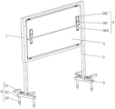
FIG. 1 is a schematic perspective view of a warning device for use in construction of electromechanical engineering according to the present invention;
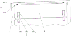
fig. 2 is a schematic view of a part of the structure of an air guiding device in a warning device for electromechanical engineering construction;
FIG. 3 is a schematic structural view of a first rectangular block in the warning device for electromechanical engineering construction of the present invention;
FIG. 4 is a schematic structural view of a second rectangular block in the warning device for electromechanical engineering construction of the present invention;
FIG. 5 is a schematic view of a part of the structure of a fixing device in the warning device for electromechanical engineering construction of the present invention;
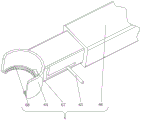
FIG. 6 is the utility model provides a structural schematic of telescopic link among the warning device of electromechanical engineering construction usefulness
Illustration of the drawings: 1. a frame body; 2. a support pillar; 3. a base plate; 4. a baffle plate; 5. an air guide device; 501. a first rectangular block; 502. a limiting rod; 503. a second rectangular block; 504. a first spring; 505. rotating the column; 506. a limiting hole; 507. a receiving groove; 508. a second spring; 509. a limiting column; 510. a push rod; 511. a placement groove; 6. a fixing device; 61. a pedal; 62. fixing a column; 63. a card slot; 64. a clamping block; 65. a slide bar; 66. a telescopic rod; 67. connecting columns; 68. an arc-shaped plate.
Detailed Description
In order to make the above objects, features and advantages of the present invention more clearly understood, the present invention will be further described with reference to the accompanying drawings and examples. It should be noted that the embodiments and features of the embodiments of the present application may be combined with each other without conflict.
In the following description, numerous specific details are set forth in order to provide a thorough understanding of the present invention, however, the present invention may be practiced in other ways than those specifically described herein, and therefore the present invention is not limited to the limitations of the specific embodiments of the present disclosure.
The specific arrangement and function of the air guide device 5 and the fixing device 6 will be described in detail below.
As shown in fig. 1 and fig. 2, four first springs 504 are distributed in groups of two by two symmetrically about the central axis of the frame 1, one end of the first spring 504 is fixedly connected to the baffle 4, the other end of the first spring 504 is fixedly connected to the frame 1, the surfaces of the two baffles 4 are respectively fixedly connected to a first rectangular block 501 and a second rectangular block 503, two sides of the first rectangular block 501 are rotatably connected to a limiting rod 502, the limiting rod 502 is U-shaped, the surface of the second rectangular block 503 is provided with a placing groove 511, the side wall of the placing groove 511 is provided with a receiving groove 507, the inner wall of the receiving groove 507 is fixedly connected to a second spring 508, the other end of the second spring 508 is fixedly connected to a limiting post 509, one end of the limiting post 509 far from the second spring 508 is semicircular, a rotating post 505 is inserted into the baffle 4, the surface of the rotating post 505 is rotatably connected to the inner wall of the baffle 4, two ends of the rotating post 505 are respectively fixedly connected to, one end of the limiting rod 502 close to the first rectangular block 501 is provided with a limiting hole 506, the size of the limiting hole 506 is matched with that of the limiting column 509, and the surface of the limiting column 509 is fixedly connected with a push rod 510.
The whole air guide device 5 achieves the effect that when strong wind comes temporarily, as the baffle 4 is rotatably connected with the frame body 1 through the rotating column 505, the wind blows over at the moment, the two baffles 4 can rotate by taking the rotating column 505 as the center, when the strong wind passes, the baffle 4 can be pulled back to the original position by the first spring 504, the limiting rod 502 is rotated at the moment, the limiting rod 502 is rotated to the placing groove 511 of the second rectangular block 503, when the limiting rod 502 touches the limiting column 509, the limiting column 509 is contracted towards the accommodating groove 507, when the limiting rod 502 completely enters the placing groove 511, the second spring 508 ejects the limiting column 509, the limiting column 509 ejects into the limiting hole 506, so that the two baffles 4 are fixed, when the push rod 510 is pulled backwards when the baffle needs to be opened, so that the drag rod drives the limiting column 509 to move towards the accommodating groove 507, and at the limiting rod 502 is pulled out again, thereby no longer fixed with two baffles 4 to let can solve current warning sign and generally can all be bigger, the warning sign all comprises a complete board moreover, when the warning sign is placed on the way and warns, runs into strong wind weather, traditional warning sign can't lead away wind, make on the warning sign is all blown to strong wind, can make the warning sign be difficult to bear the power of strong wind, thereby the problem of blowing away the warning sign.
As shown in fig. 1 and 5, two supporting columns 2 are fixedly connected to one end of a frame 1, a bottom plate 3 is fixedly connected to one end of each supporting column 2, which is far away from the frame 1, through holes are formed in both ends of the bottom plate 3, a fixing device 6 is arranged on the surface of the bottom plate 3, the fixing device 6 comprises a fixing column 62, the surface of the fixing column 62 is in sliding connection with the through holes, one end of the fixing column 62 is conical, a pedal 61 is fixedly connected to the other end of the fixing column 62, a clamping groove 63 is formed in the surface of the fixing column 62, an expansion link 66 is fixedly connected to one end of each supporting column 2, which is close to the fixing column 62, the expansion link 66 is composed of two hollow rods with different sizes, a small sliding surface is in sliding connection with the inner wall of a large rod, a clamping block 64 is fixedly connected, the one end fixedly connected with arc 68 of spliced pole 67, a plurality of blades of the inner wall fixedly connected with of arc 68, "L" shape groove has been seted up on the surface of telescopic link 66, and the inner wall sliding connection in groove has slide bar 65, and in slide bar 65's one end stretched into telescopic link 66, and slide bar 65's one end and spliced pole 67 fixed connection.
The whole fixing device 6 has the effects that the fixing device 6 is arranged, the pedal 61 is trampled, the fixing column 62 is inserted into the soil to fix the warning board, when the warning board needs to be moved, the fixing column 62 is pulled out of the soil, a large amount of soil exists in the clamping groove 63 of the fixing column 62, the clamping block 64 and the clamping groove 63 are difficult to clamp, the clamping groove 63 and the telescopic rod 66 are at the same position, the sliding rod 65 slides at the moment, the sliding rod 65 drives the connecting column 67 and the arc-shaped plate 68 to slide, the surface of the blade in the arc-shaped plate 68 is contacted with the surface of the clamping groove 63, the sliding rod 65 slides up and down at the short arm end of the L-shaped groove at the moment, the arc-shaped plate 68 also slides up and down, the soil in the clamping groove 63 is scraped down by the blade in the arc-shaped plate 68, the arc-shaped plate 68 is pulled back, the clamping block 64 and the clamping groove 63 at one end of the telescopic rod 66 are clamped, so that the problem that the clamping block 64 and the clamping groove 63 are difficult to fix due to the fact that a large amount of soil exists in the clamping groove 63 after the soil is pulled out of the existing warning board is solved.
The whole working principle is that because the traditional warning board has no air guide device 5, the warning board can be blown away in the windy weather, at the moment, when the windy weather comes, because the baffle 4 is rotationally connected with the frame body 1 through the rotating column 505, the wind blows, the two baffles 4 can rotate by taking the rotating column 505 as the center, when the windy weather comes, the first spring 504 can pull the baffle 4 back to the original position, the limiting rod 502 is rotated at the moment, the limiting rod 502 is rotated to the placing groove 511 of the second rectangular block 503, when the limiting rod 502 touches the limiting column 509, the limiting column 509 is contracted towards the containing groove 507, when the limiting rod 502 completely enters the placing groove 511, the second spring 508 pops the limiting column 509 out, the limiting column 509 is popped into the limiting hole 506, so that the two baffles 4 are fixed, when the warning board needs to be opened, the push rod 510 is pulled backwards, so that the tow rod drives the limiting column 509 to move towards the containing groove 507, at this moment, the limiting rod 502 is pulled out, so that the two baffle plates 4 are not fixed, the problem that the existing warning board is large in size and is composed of a complete plate, when the warning board is placed on the road for warning, in windy weather, the traditional warning board cannot guide wind away, so that the warning board is difficult to bear the force of the windy weather, and the warning board is blown away is solved, the warning board is not provided with a device for fixing the fixed column 62, at this moment, the fixed column 62 is inserted into the soil by stepping on the pedal 61 through the fixing device 6, so that the warning board is fixed, when the warning board needs to be moved, the fixed column 62 is pulled out, because the fixed column 62 is pulled out from the soil, a large amount of soil exists in the clamping groove 63 of the fixed column 62, the clamping blocks 64 and the clamping groove 63 are difficult to clamp, and at this moment, the clamping groove 63 and the telescopic rod 66 are at the same position, slide bar 65 slides this moment, make slide bar 65 drive spliced pole 67 and arc 68 and slide, make blade and draw-in groove 63 surface in the arc 68 contact, slide bar 65 slides from top to bottom at the short armed end department in "L" shape groove this moment, thereby make arc 68 also slide from top to bottom, scrape down the earth in the draw-in groove 63 through the blade in the arc 68, after scraping again draw arc 68 back telescopic link 66 in, stimulate telescopic link 66 this moment, make the fixture block 64 and the draw-in groove 63 looks joint of telescopic link 66 one end, thereby can solve current warning sign after extracting earth, there is a large amount of earth in the draw-in groove 63, make fixture block 64 and draw-in groove 63 be difficult to the fixed problem.
The above description is only a preferred embodiment of the present invention, and is not intended to limit the present invention in other forms, and any person skilled in the art may use the above-mentioned technical contents to change or modify the equivalent embodiment into equivalent changes and apply to other fields, but any simple modification, equivalent change and modification made to the above embodiments according to the technical matters of the present invention will still fall within the protection scope of the technical solution of the present invention.
Claims (6)
1. The utility model provides a warning device that electromechanical engineering construction was used, includes framework (1), baffle (4) and air ducting (5), its characterized in that: the air guide device is characterized in that two baffle plates (4) are rotatably connected inside the frame body (1), air guide devices (5) are arranged on the surfaces of the two baffle plates (4), each air guide device (5) comprises four first springs (504), the four first springs (504) are distributed symmetrically with the central axis of the frame body (1) in a group, one end of each first spring (504) is fixedly connected with the corresponding baffle plate (4), the other end of each first spring (504) is fixedly connected with the frame body (1), the surfaces of the two baffle plates (4) are respectively fixedly connected with a first rectangular block (501) and a second rectangular block (503), two sides of each first rectangular block (501) are rotatably connected with limiting rods (502), each limiting rod (502) is U-shaped, a placement groove (511) is formed in the surface of each second rectangular block (503), and a storage groove (507) is formed in the side wall of each placement groove (511), the inner wall fixedly connected with second spring (508) of holding groove (507), the other end fixedly connected with spacing post (509) of second spring (508), the one end semicircular in shape that second spring (508) was kept away from in spacing post (509).
2. The warning device for the electromechanical engineering construction according to claim 1, wherein: the baffle plate is characterized in that a rotating column (505) is inserted into the baffle plate (4), the surface of the rotating column (505) is rotatably connected with the inner wall of the baffle plate (4), and two ends of the rotating column (505) are fixedly connected with the frame body (1) respectively.
3. The warning device for the electromechanical engineering construction according to claim 1, wherein: spacing hole (506) have been seted up to the one end that gag lever post (502) are close to first rectangular block (501), the size of spacing hole (506) and the size phase-match of spacing post (509), the fixed surface of spacing post (509) is connected with push rod (510).
4. The warning device for the electromechanical engineering construction according to claim 1, wherein: one end of the frame body (1) is fixedly connected with two supporting columns (2), one end of each supporting column (2) far away from the frame body (1) is fixedly connected with a bottom plate (3), through holes are arranged at both ends of the bottom plate (3), a fixing device (6) is arranged on the surface of the bottom plate (3), the fixing device (6) comprises a fixing column (62), the surface of the fixing column (62) is connected with the through hole in a sliding mode, one end of the fixed column (62) is conical, the other end of the fixed column (62) is fixedly connected with a pedal (61), a clamping groove (63) is formed in the surface of the fixed column (62), a telescopic rod (66) is fixedly connected to one end, close to the fixed column (62), of the supporting column (2), the other end of the telescopic rod (66) is fixedly connected with a clamping block (64), the clamping block (64) is arc-shaped, and the size of the clamping block (64) is matched with that of the clamping groove (63).
5. The warning device for the electromechanical engineering construction according to claim 4, wherein: the inner wall sliding connection of telescopic link (66) has spliced pole (67), the one end fixedly connected with arc (68) of spliced pole (67), a plurality of blades of the inner wall fixedly connected with of arc (68).
6. The warning device for the electromechanical engineering construction according to claim 4, wherein: the surface of telescopic link (66) is seted up "L" shape groove, and the inner wall sliding connection in groove has slide bar (65), the one end of slide bar (65) stretches into in telescopic link (66), and the one end and spliced pole (67) fixed connection of slide bar (65).
Priority Applications (1)
| Application Number | Priority Date | Filing Date | Title |
|---|---|---|---|
| CN202022021944.0U CN213448195U (en) | 2020-09-16 | 2020-09-16 | Warning device for electromechanical engineering construction |
Applications Claiming Priority (1)
| Application Number | Priority Date | Filing Date | Title |
|---|---|---|---|
| CN202022021944.0U CN213448195U (en) | 2020-09-16 | 2020-09-16 | Warning device for electromechanical engineering construction |
Publications (1)
| Publication Number | Publication Date |
|---|---|
| CN213448195U true CN213448195U (en) | 2021-06-15 |
Family
ID=76324032
Family Applications (1)
| Application Number | Title | Priority Date | Filing Date |
|---|---|---|---|
| CN202022021944.0U Expired - Fee Related CN213448195U (en) | 2020-09-16 | 2020-09-16 | Warning device for electromechanical engineering construction |
Country Status (1)
| Country | Link |
|---|---|
| CN (1) | CN213448195U (en) |
Cited By (1)
| Publication number | Priority date | Publication date | Assignee | Title |
|---|---|---|---|---|
| CN115341493A (en) * | 2022-08-19 | 2022-11-15 | 秦皇岛南达路桥建筑工程有限公司 | Safety warning device is used in road and bridge construction |
-
2020
- 2020-09-16 CN CN202022021944.0U patent/CN213448195U/en not_active Expired - Fee Related
Cited By (1)
| Publication number | Priority date | Publication date | Assignee | Title |
|---|---|---|---|---|
| CN115341493A (en) * | 2022-08-19 | 2022-11-15 | 秦皇岛南达路桥建筑工程有限公司 | Safety warning device is used in road and bridge construction |
Similar Documents
| Publication | Publication Date | Title |
|---|---|---|
| CN210743504U (en) | Multifunctional display device for indoor design | |
| CN218823246U (en) | A forestry investigation instrument for carbon hui lin management | |
| CN214955492U (en) | Preschool education intelligence-developing model | |
| CN209746867U (en) | Portable device applied to Japanese professional learning tutoring | |
| CN211124568U (en) | An auxiliary demonstration device for English teaching | |
| CN216467570U (en) | traffic engineering guide | |
| CN209652798U (en) | An environmental protection and energy saving road construction warning device | |
| CN220873152U (en) | Word memory link plate | |
| CN214175425U (en) | Think political affairs classroom teaching auxiliary device | |
| CN209149617U (en) | A kind of board for teaching mathematics | |
| CN218416420U (en) | Novel power status lamp for router | |
| CN211646086U (en) | Municipal works road warning light | |
| CN211827725U (en) | A display device for the division of Chinese literature vocabulary | |
| CN215190178U (en) | Data swing frame for real estate management personnel | |
| CN219714795U (en) | Soil sampler | |
| CN218861386U (en) | a road guidance device | |
| CN214253564U (en) | Letter card for English enlightenment education | |
| CN213849302U (en) | Multifunctional music teaching board | |
| CN211212169U (en) | Wall map frame for English study | |
| CN220953067U (en) | Warning device for municipal road and bridge construction | |
| CN220384654U (en) | Adjustable wall map frame | |
| CN221895634U (en) | A warning device for municipal road construction | |
| CN218686210U (en) | Portable ball timing device of scoreing | |
| CN216467060U (en) | A display device for english teaching sentence analysis | |
| CN211376052U (en) | A kind of route guide device for tourism management |
Legal Events
| Date | Code | Title | Description |
|---|---|---|---|
| GR01 | Patent grant | ||
| GR01 | Patent grant | ||
| CF01 | Termination of patent right due to non-payment of annual fee |
Granted publication date: 20210615 |
|
| CF01 | Termination of patent right due to non-payment of annual fee |