CN213439239U - Graphite part clamping device convenient for force adjustment - Google Patents
Graphite part clamping device convenient for force adjustment Download PDFInfo
- Publication number
- CN213439239U CN213439239U CN202022053695.3U CN202022053695U CN213439239U CN 213439239 U CN213439239 U CN 213439239U CN 202022053695 U CN202022053695 U CN 202022053695U CN 213439239 U CN213439239 U CN 213439239U
- Authority
- CN
- China
- Prior art keywords
- plate
- graphite
- rod
- clamping device
- connecting rod
- Prior art date
- Legal status (The legal status is an assumption and is not a legal conclusion. Google has not performed a legal analysis and makes no representation as to the accuracy of the status listed.)
- Active
Links
- OKTJSMMVPCPJKN-UHFFFAOYSA-N Carbon Chemical group [C] OKTJSMMVPCPJKN-UHFFFAOYSA-N 0.000 title claims abstract description 50
- 229910002804 graphite Inorganic materials 0.000 claims abstract description 40
- 239000010439 graphite Substances 0.000 claims abstract description 40
- 235000017166 Bambusa arundinacea Nutrition 0.000 claims abstract 3
- 235000017491 Bambusa tulda Nutrition 0.000 claims abstract 3
- 241001330002 Bambuseae Species 0.000 claims abstract 3
- 235000015334 Phyllostachys viridis Nutrition 0.000 claims abstract 3
- 239000011425 bamboo Substances 0.000 claims abstract 3
- 230000010354 integration Effects 0.000 abstract description 3
- 230000001105 regulatory effect Effects 0.000 abstract description 3
- 238000003466 welding Methods 0.000 abstract description 3
- 238000004519 manufacturing process Methods 0.000 description 3
- 206010066054 Dysmorphism Diseases 0.000 description 1
- 230000009286 beneficial effect Effects 0.000 description 1
- 230000004048 modification Effects 0.000 description 1
- 238000012986 modification Methods 0.000 description 1
- 239000007787 solid Substances 0.000 description 1
- 238000004804 winding Methods 0.000 description 1
Images



Landscapes
- Clamps And Clips (AREA)
Abstract
The utility model discloses a make things convenient for graphite part clamping device that dynamics was adjusted, including operation panel and graphite cake body, the inside swing joint of operation panel has the bracing piece, and the upside integration of bracing piece is provided with first grip block, the inboard below swing joint of bracing piece has the head rod, the upside welding of fixed plate has left connecting plate, and the downside middle part of left connecting plate is provided with the retainer plate, one side integration that left connecting plate was kept away from to the retainer plate is provided with the regulation section of thick bamboo, the right side welding of left connecting plate has preceding connecting strip, the rear side swing joint of regulating wheel has the back connecting strip. This graphite part clamping device who makes things convenient for dynamics to adjust can effectively adjust the dynamics of centre gripping according to the graphite cake of different models size, conveniently adjusts and fixes, and is easy and simple to handle, and stable in structure can improve work efficiency, and can be effectively spacing, is applicable to the graphite cake of different thickness, and the flexibility is strong.
Description
Technical Field
The utility model relates to a graphite cake production technical field specifically is a graphite parts clamping device who makes things convenient for dynamics to adjust.
Background
The graphite component can be used for producing graphite electrodes, graphite crucibles, graphite molds and the like; current graphite production clamping device, inconvenient according to the not dynamics of the graphite cake regulation centre gripping of equidimension, work efficiency is lower, and inconvenient graphite cake that is applicable to different thickness, and the flexibility is not strong enough, consequently, we provide a graphite part clamping device who makes things convenient for the dynamics to adjust to in solving the problem that proposes in the aforesaid.
SUMMERY OF THE UTILITY MODEL
An object of the utility model is to provide a make things convenient for graphite part clamping device that dynamics was adjusted to solve the current graphite cake production that proposes among the above-mentioned background art and adjust the dynamics of centre gripping with clamping device inconvenient according to the graphite cake of different models size, work efficiency is lower, and the inconvenient graphite cake that is applicable to different thickness, the not strong enough problem of flexibility.
In order to achieve the above object, the utility model provides a following technical scheme: a graphite part clamping device convenient for force adjustment comprises an operation table and a graphite plate body, wherein a supporting rod is movably connected inside the operation table, a first clamping plate is integrally arranged on the upper side of the supporting rod, a first connecting rod is movably connected below the inner side of the supporting rod, a fixing plate is tightly attached to the middle part of the outer side of the first connecting rod, a left connecting plate is welded on the upper side of the fixing plate, a fixing ring is arranged in the middle part of the lower side of the left connecting plate, an adjusting cylinder is integrally arranged on one side of the fixing ring away from the left connecting plate, a second connecting rod is arranged inside the adjusting cylinder, a front connecting strip is welded on the right side of the left connecting plate, an adjusting wheel is tightly attached to the rear side of the front connecting strip, the adjusting wheel is rotatably connected to the operation table, a rear connecting strip is movably connected to the rear side of the adjusting wheel, and a, and the upside of right side connecting plate installs the second grip block, the outside of regulating wheel is provided with the limiting plate, and the outside of limiting plate is fixed with the lug, the downside integration of limiting plate is provided with solid fixed ring, and limiting plate sliding connection is at the downside of operation panel, the inboard of first grip block is pasted and is connected with the rubber pad, and the internally mounted of first grip block has the gag lever post, the outside winding of gag lever post has the spring, and the upside of gag lever post is fixed with the roof, the upside of graphite cake body closely laminates there is the roof.
Preferably, the first connecting rod and the second connecting rod are connected with the adjusting cylinder in a threaded connection mode, the thread directions of the first connecting rod and the second connecting rod are opposite, the first connecting rod forms a rotating structure on the supporting rod, and the supporting rod is connected with the operating table in a clamping groove connection mode.
Preferably, the adjusting cylinder is connected with the left connecting plate clamping groove through a fixing ring, the left connecting plate forms a sliding structure on the operating table, and the length of the cross section of the outer side of the fixing ring is larger than that of the cross section of the inner side of the fixing ring.
Preferably, the adjusting wheel and the front connecting strip are connected in a meshing connection mode, and the moving directions of the front connecting strip and the rear connecting strip are opposite.
Preferably, the regulating wheel and the limiting plate are connected in a meshing connection mode, and the limiting plate and the bump are symmetrically arranged about a vertical central axis of the fixing ring.
Preferably, the top plate forms a sliding structure on the first clamping plate through a limiting rod, and the longitudinal section of the limiting rod is of a T-shaped structure.
Compared with the prior art, the beneficial effects of the utility model are that: the graphite component clamping device convenient for force adjustment can effectively adjust clamping force according to graphite plates of different types and sizes, is convenient to adjust and fix, is simple and convenient to operate, has a stable structure, can improve working efficiency, can effectively limit the position, is suitable for graphite plates of different thicknesses, and is high in flexibility;
1. the clamping device is provided with an adjusting cylinder, a first connecting rod and a supporting rod, the first connecting rod and the second connecting rod with opposite thread directions move in opposite directions by rotating the adjusting cylinder, the first connecting rod and the second connecting rod rotate on the supporting rod, the supporting rod connected with the clamping groove of the operating platform drives the first clamping plate welded on the upper side to slide in opposite directions, and clamping force can be effectively adjusted according to graphite plates of different types and sizes;
2. the adjusting wheel, the rear connecting strip and the limiting plate are arranged on the operating platform, the adjusting wheel connected with the clamping groove is rotated on the operating platform, the rear connecting strip and the front connecting strip are meshed with the adjusting wheel to downwards shift the fixing ring, the limiting plate is connected with the clamping groove of the adjusting wheel, the limiting plate and the adjusting wheel are prevented from rotating in the operating platform by the bump, the adjusting wheel is convenient to adjust and fix, the operation is simple and convenient, the structure is stable, and the working efficiency can be improved;
3. be provided with gag lever post, spring and roof, through stimulate the roof of being connected with its draw-in groove on bracing piece and second grip block respectively, rotate the roof on the gag lever post, the position of adjustment roof, the elastic action of spring promotes the downside of roof and the upside of graphite cake body and closely laminates, can be effectively spacing, is applicable to the graphite cake of different thickness, and the flexibility is strong.
Drawings
FIG. 1 is a schematic side view of the cross-sectional structure of the present invention;
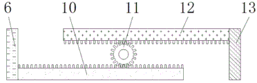
FIG. 2 is a schematic view of the connection structure of the rear connecting strip and the adjusting wheel of the present invention;
FIG. 3 is a schematic view of the overall structure of the adjusting wheel and the bump according to the present invention;
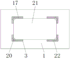
FIG. 4 is a schematic view of the connection structure of the rubber pad and the graphite plate body;
fig. 5 is a schematic view of the front cross-sectional structure of the connection between the limiting rod and the first clamping plate of the present invention.
In the figure: 1. an operation table; 2. a support bar; 3. a first clamping plate; 4. a first connecting rod; 5. a fixing plate; 6. a left connecting plate; 7. a stationary ring; 8. an adjusting cylinder; 9. a second connecting rod; 10. a front connecting strip; 11. an adjustment wheel; 12. a rear connecting strip; 13. a right connecting plate; 14. a bump; 15. a limiting plate; 16. a fixing ring; 17. a rubber pad; 18. a limiting rod; 19. a spring; 20. a top plate; 21. a graphite plate body; 22. a second clamping plate.
Detailed Description
The technical solutions in the embodiments of the present invention will be described clearly and completely with reference to the accompanying drawings in the embodiments of the present invention, and it is obvious that the described embodiments are only some embodiments of the present invention, not all embodiments. Based on the embodiments in the present invention, all other embodiments obtained by a person skilled in the art without creative work belong to the protection scope of the present invention.
Referring to fig. 1-5, the present invention provides a technical solution: a graphite part clamping device convenient for force adjustment comprises an operation table 1, a support rod 2, a first clamping plate 3, a first connecting rod 4, a fixing plate 5, a left connecting plate 6, a fixing ring 7, an adjusting cylinder 8, a second connecting rod 9, a front connecting strip 10, an adjusting wheel 11, a rear connecting strip 12, a right connecting plate 13, a convex block 14, a limiting plate 15, a fixing ring 16, a rubber pad 17, a limiting rod 18, a spring 19, a top plate 20, a graphite plate body 21 and a second clamping plate 22, wherein the inside of the operation table 1 is movably connected with the support rod 2, the upper side of the support rod 2 is integrally provided with the first clamping plate 3, the lower side of the inner side of the support rod 2 is movably connected with the first connecting rod 4, the middle part of the outer side of the first connecting rod 4 is tightly attached with the fixing plate 5, the left connecting plate 6 is welded on the upper side of the fixing plate 5, an adjusting cylinder 8 is integrally arranged on one side, away from a left connecting plate 6, of the fixing ring 7, a second connecting rod 9 is arranged inside the adjusting cylinder 8, a front connecting strip 10 is welded on the right side of the left connecting plate 6, an adjusting wheel 11 is tightly attached to the rear side of the front connecting strip 10, the adjusting wheel 11 is rotatably connected to the operating platform 1, a rear connecting strip 12 is movably connected to the rear side of the adjusting wheel 11, a right connecting plate 13 is installed on the right side of the rear connecting strip 12, a second clamping plate 22 is installed on the upper side of the right connecting plate 13, a limiting plate 15 is arranged on the outer side of the adjusting wheel 11, a lug 14 is fixed on the outer side of the limiting plate 15, a fixing ring 16 is integrally arranged on the lower side of the limiting plate 15, the limiting plate 15 is slidably connected to the lower side of the operating platform 1, a rubber pad 17 is adhered to the inner side of the first clamping plate 3, a limiting rod 18, and the upper side of the limiting rod 18 is fixed with a top plate 20, and the upper side of the graphite plate body 21 is tightly attached with the top plate 20.
As shown in fig. 1, the first connecting rod 4 and the second connecting rod 9 are connected with the adjusting cylinder 8 by a threaded connection manner, the thread directions of the first connecting rod 4 and the second connecting rod 9 are opposite, the first connecting rod 4 forms a rotating structure on the supporting rod 2, and the supporting rod 2 is connected with the operating platform 1 by a clamping groove connection manner, so that the distance between the first clamping plates 3 can be conveniently adjusted, as shown in fig. 1, the adjusting cylinder 8 is connected with the clamping groove of the left connecting plate 6 by the fixing ring 7, the left connecting plate 6 forms a sliding structure on the operating platform 1, and the length of the outer side cross section of the fixing ring 7 is greater than that of the inner side cross section, so that the adjusting cylinder 8 can be effectively limited;
the adjusting wheel 11 and the front connecting strip 10 are connected in a meshing connection mode as shown in fig. 2, the moving directions of the front connecting strip 10 and the rear connecting strip 12 are opposite, the distance between the left connecting plate 6 and the right connecting plate 13 can be conveniently adjusted, the adjusting wheel 11 and the limiting plate 15 are connected in a meshing connection mode as shown in fig. 3, the limiting plate 15 and the bump 14 are symmetrically arranged about a vertical central axis of the fixing ring 16, the adjusting wheel 11 can be effectively fixed, a top plate 20 forms a sliding structure on the first clamping plate 3 through the limiting rod 18 as shown in fig. 5, the longitudinal section of the limiting rod 18 is of a T-shaped structure, and the graphite plate body 21 can be conveniently fixed.
The working principle is as follows: when the graphite component clamping device convenient for force adjustment is used, firstly, as shown in attached figures 1 and 4, the adjusting cylinder 8 is rotated, the fixing ring 7 integrally arranged at the outer side of the adjusting cylinder 8 slides in the left connecting plate 6, the adjusting cylinder 8 is limited, the first connecting rod 4 and the second connecting rod 9 which are connected by the threads inside the adjusting cylinder 8 are opposite in thread direction, and the outer sides of the first connecting rod 4 and the second connecting rod 9 are tightly attached with the fixing plate 5, when the adjusting cylinder 8 rotates, the first connecting rod 4 and the second connecting rod 9 move in opposite directions, the first connecting rod 4 and the second connecting rod 9 rotate on the supporting rod 2 and push the symmetrically arranged supporting rods 2 to move, the support rod 2 connected with the clamping groove of the operating platform 1 drives the first clamping plates 3 welded on the upper side to slide in opposite directions, so that the distance between the first clamping plates 3 is adjusted;
as shown in fig. 2, fig. 3 and fig. 4, when the distance between the first clamping plate 3 and the second clamping plate 22 needs to be adjusted, the adjusting wheel 11 connected with the clamping groove thereof is rotated on the operation table 1, the rear connecting strip 12 and the front connecting strip 10 meshed and connected with the outer side of the adjusting wheel 11 slide in opposite directions and respectively push the right connecting plate 13 and the left connecting plate 6 to move, the left connecting plate 6 and the right connecting plate 13 respectively drive the first clamping plate 3 and the second clamping plate 22 mounted thereon to slide, after the adjustment is completed, the fixing ring 16 is shifted downwards, the limiting plate 15 mounted on the fixing ring 16 slides in the operation table 1, the limiting plate 15 is connected with the clamping groove of the adjusting wheel 11, and the bump 14 limits the limiting plate 15, so as to prevent the limiting plate 15 and the adjusting wheel 11 from rotating in the operation table 1;
as shown in fig. 1, 4 and 5, a graphite plate body 21 is placed on an operation table 1, so that the outer side of the graphite plate body 21 is respectively tightly attached to rubber pads 17 attached to a first clamping plate 3 and a second clamping plate 22, then a top plate 20 connected to a clamping groove of the support rod 2 and the second clamping plate 22 is respectively pulled on the support rod 2 and the second clamping plate 22, the top plate 20 is rotated on a limiting rod 18, the position of the top plate 20 is adjusted and released, the elastic action of a spring 19 pushes the limiting rod 18 to reset, so that the lower side of the top plate 20 is tightly attached to the upper side of the graphite plate body 21, the graphite plate body 21 is limited, and a series of operations of the graphite component clamping device with convenient force adjustment are completed.
The utility model discloses the standard part that uses all can purchase from the market, and dysmorphism piece all can be customized according to the description with the record of drawing of description, and the concrete connection mode of each part all adopts conventional means such as ripe bolt, rivet, welding among the prior art, and machinery, part and equipment all adopt prior art, and conventional model, including circuit connection adopts conventional connection mode among the prior art, does not detailed here again.
Although the present invention has been described in detail with reference to the foregoing embodiments, it will be apparent to those skilled in the art that modifications may be made to the embodiments or portions thereof without departing from the spirit and scope of the invention.
Claims (6)
1. The utility model provides a graphite part clamping device that convenient dynamics was adjusted, includes operation panel (1) and graphite cake body (21), its characterized in that: the inner part of the operating platform (1) is movably connected with a support rod (2), a first clamping plate (3) is integrally arranged on the upper side of the support rod (2), a first connecting rod (4) is movably connected to the lower side of the inner side of the support rod (2), a fixing plate (5) is tightly attached to the middle part of the outer side of the first connecting rod (4), a left connecting plate (6) is welded on the upper side of the fixing plate (5), a fixing ring (7) is arranged in the middle part of the lower side of the left connecting plate (6), an adjusting cylinder (8) is integrally arranged on one side, far away from the left connecting plate (6), of the fixing ring (7), a second connecting rod (9) is arranged inside the adjusting cylinder (8), a front connecting strip (10) is welded on the right side of the left connecting plate (6), an adjusting wheel (11) is tightly attached to the rear side of the front connecting strip (10), and the adjusting wheel, the rear side of the adjusting wheel (11) is movably connected with a rear connecting strip (12), the right side of the rear connecting strip (12) is provided with a right connecting plate (13), a second clamping plate (22) is arranged on the upper side of the right connecting plate (13), a limiting plate (15) is arranged on the outer side of the adjusting wheel (11), a convex block (14) is fixed at the outer side of the limit plate (15), a fixed ring (16) is integrally arranged at the lower side of the limit plate (15), the limiting plate (15) is connected to the lower side of the operating platform (1) in a sliding manner, a rubber pad (17) is connected to the inner side of the first clamping plate (3) in a sticking manner, a limiting rod (18) is arranged in the first clamping plate (3), a spring (19) is wound on the outer side of the limiting rod (18), and the upper side of the limiting rod (18) is fixed with a top plate (20), and the upper side of the graphite plate body (21) is tightly attached with the top plate (20).
2. The graphite component clamping device convenient for force adjustment according to claim 1, wherein: the utility model discloses a clamping groove type adjustable clamping device, including a regulation section of thick bamboo, first connecting rod (4) and second connecting rod (9) all are connected with regulation section of thick bamboo (8) adoption threaded connection's mode, and the screw thread opposite direction of first connecting rod (4) and second connecting rod (9) to first connecting rod (4) constitute rotating-structure on bracing piece (2), and bracing piece (2) and operation panel (1) adopt the mode of draw-in groove connection to be connected moreover.
3. The graphite component clamping device convenient for force adjustment according to claim 1, wherein: the adjusting cylinder (8) is connected with the clamping groove of the left connecting plate (6) through the fixing ring (7), the left connecting plate (6) forms a sliding structure on the operating table (1), and the length of the cross section of the outer side of the fixing ring (7) is larger than that of the cross section of the inner side of the fixing ring.
4. The graphite component clamping device convenient for force adjustment according to claim 1, wherein: the adjusting wheel (11) is connected with the front connecting strip (10) in a meshing connection mode, and the moving directions of the front connecting strip (10) and the rear connecting strip (12) are opposite.
5. The graphite component clamping device convenient for force adjustment according to claim 1, wherein: the adjusting wheel (11) is connected with the limiting plate (15) in a meshing connection mode, and the limiting plate (15) and the bump (14) are symmetrically arranged about a vertical central axis of the fixing ring (16).
6. The graphite component clamping device convenient for force adjustment according to claim 1, wherein: the top plate (20) forms a sliding structure on the first clamping plate (3) through a limiting rod (18), and the longitudinal section of the limiting rod (18) is of a T-shaped structure.
Priority Applications (1)
| Application Number | Priority Date | Filing Date | Title |
|---|---|---|---|
| CN202022053695.3U CN213439239U (en) | 2020-09-18 | 2020-09-18 | Graphite part clamping device convenient for force adjustment |
Applications Claiming Priority (1)
| Application Number | Priority Date | Filing Date | Title |
|---|---|---|---|
| CN202022053695.3U CN213439239U (en) | 2020-09-18 | 2020-09-18 | Graphite part clamping device convenient for force adjustment |
Publications (1)
| Publication Number | Publication Date |
|---|---|
| CN213439239U true CN213439239U (en) | 2021-06-15 |
Family
ID=76325279
Family Applications (1)
| Application Number | Title | Priority Date | Filing Date |
|---|---|---|---|
| CN202022053695.3U Active CN213439239U (en) | 2020-09-18 | 2020-09-18 | Graphite part clamping device convenient for force adjustment |
Country Status (1)
| Country | Link |
|---|---|
| CN (1) | CN213439239U (en) |
Cited By (1)
| Publication number | Priority date | Publication date | Assignee | Title |
|---|---|---|---|---|
| CN120886194A (en) * | 2025-09-30 | 2025-11-04 | 巴中意科碳素股份有限公司 | A clamping device for easily holding graphite products |
-
2020
- 2020-09-18 CN CN202022053695.3U patent/CN213439239U/en active Active
Cited By (1)
| Publication number | Priority date | Publication date | Assignee | Title |
|---|---|---|---|---|
| CN120886194A (en) * | 2025-09-30 | 2025-11-04 | 巴中意科碳素股份有限公司 | A clamping device for easily holding graphite products |
Similar Documents
| Publication | Publication Date | Title |
|---|---|---|
| CN210633205U (en) | Multifunctional clamp convenient for overturning for machining | |
| CN211282839U (en) | Material clamping device for carrying equipment | |
| CN108975026A (en) | A kind of film contained side device of casting machine | |
| CN218079641U (en) | Flattening mechanism for photovoltaic solder strip | |
| CN210352032U (en) | PCB fixing device of SMT chip mounter | |
| CN210587412U (en) | High efficiency pipe cutting machine | |
| CN213223815U (en) | Stamping part repairing device | |
| CN210255788U (en) | Adjustable bearing production clamping device | |
| CN113102553A (en) | Adjustable shaping tool for power distribution cabinet body | |
| CN215344667U (en) | Auxiliary device for video shooting | |
| CN213730107U (en) | Lithium cell production is with high-efficient spot welding device | |
| CN216074844U (en) | Warning device for construction | |
| CN213888494U (en) | Workpiece surface cutting device convenient to clamp for machining | |
| CN208069926U (en) | A kind of Integral frame fixing device of carbon fibre materials | |
| CN210732485U (en) | Manipulator clamp | |
| CN209335136U (en) | A kind of automatic production line high-precision device with clamping function | |
| CN114025509A (en) | Mounting device for electronic component correction | |
| CN209320318U (en) | A kind of hot press of uniform force | |
| CN210336005U (en) | Transplanting clamping device for assembling new energy battery | |
| CN113370832A (en) | Power battery module gets device of putting fast | |
| CN220516571U (en) | Clamping device for lithium battery production | |
| CN211792562U (en) | Novel general type rotation type ONU equipment support | |
| CN210588897U (en) | Photovoltaic board overhauls presses and holds mechanism | |
| CN218695667U (en) | Special rolling straight seam welding machine | |
| CN219325335U (en) | Template with double-layer structure |
Legal Events
| Date | Code | Title | Description |
|---|---|---|---|
| GR01 | Patent grant | ||
| GR01 | Patent grant |