Clamp for vertical numerically controlled lathe
Technical Field
The utility model belongs to the technical field of the numerical control lathe, especially, relate to a vertical anchor clamps for numerical control lathe.
Background
The vertical numerically controlled lathe can measure automatically in machining process, compensate automatically the error caused by cutter wear and other reasons, and make parts with complicated shape and difficult machining in common lathe in programming mode. The main shaft of the vertical numerically controlled lathe is vertical and is provided with a circular workbench for mounting a workpiece or a pipe fitting, and in the machining process, a clamp is often used for clamping and fixing the workpiece or the pipe fitting.
The clamp for the vertical numerically controlled lathe in the prior art has the following defects in the use process: 1. the structure is single, only workpieces or pipe fittings within a certain pipe diameter range can be fixed, and the adaptability is poor; 2. the clamping force is insufficient, the clamping effect is poor, the workpiece or the pipe fitting is easy to shift and deviate in the machining process, and the machining quality is influenced; 3. only one workpiece or pipe fitting can be clamped by one clamp, and the machining efficiency is influenced.
SUMMERY OF THE UTILITY MODEL
The utility model discloses aim at solves the above-mentioned technical problem that exists among the prior art, provides a vertical anchor clamps for numerical control lathe, novel structure, and the clamping is reliable, and strong adaptability once can the centre gripping two to machining efficiency has been improved.
In order to solve the technical problem, the utility model discloses a following technical scheme:
the utility model provides a vertical anchor clamps for numerical control lathe, includes the mounting bracket, its characterized in that: the mounting frame is provided with a driving mechanism and a fixing plate, one end of the driving mechanism is connected with a triangular transmission block, the fixing plate is provided with a mounting plate, one side of the mounting plate is provided with a placing table, the top surface and the bottom surface of the placing table are both provided with V-shaped grooves, the mounting plate is connected with a clamping rod, one end of the clamping rod is provided with an arc-shaped pressing plate, and a transmission rod is connected between the clamping rod and the triangular transmission block; the clamp is novel in structure, reliable in clamping and strong in adaptability, and can clamp two workpieces at a time, so that the machining efficiency is improved.
Furthermore, triangular racks are distributed in the V-shaped groove at equal intervals, the roughness of the surface of the V-shaped groove is increased, so that friction force is improved, the pipe fitting is not prone to freely sliding after being placed, and operation is facilitated.
Further, actuating mechanism drives piston push rod including driving actuating cylinder and piston push rod, drives actuating cylinder and connects piston push rod, and piston push rod connects the triangle driving block, drives actuating cylinder and drives piston push rod and carry out concertina movement, and piston push rod drives the transfer line reciprocating motion through the triangle driving block to realize the inside and outside swing of clamping bar.
Furthermore, a guide sleeve is arranged on the fixed plate, the piston push rod penetrates through the guide sleeve, the guide sleeve plays a role in guiding the piston push rod, and the phenomenon that the piston push rod radially moves to influence the practicability of the clamp is avoided.
Furthermore, a reinforcing rod is arranged between the mounting frame and the fixing plate, so that the connecting strength between the mounting frame and the fixing plate is improved, the mounting frame and the fixing plate are connected into a whole, and the structure is stable.
Furthermore, a triangular reinforcing block is arranged between the clamping rod and the arc-shaped pressing plate, so that the connection strength between the clamping rod and the arc-shaped pressing plate is improved, the joint of the clamping rod and the arc-shaped pressing plate is not easy to crack or break, and the use is reliable.
Further, the bottom symmetric distribution of mounting bracket has the stabilizer blade, is equipped with the installation piece on the stabilizer blade, is equipped with the mounting hole on the installation piece, to the nailing in the mounting hole, fixes the mounting bracket to vertical numerical control lathe's workstation, and it is convenient to install, and the stabilizer blade gives the mounting bracket support, makes the mounting bracket break away from the workstation, guarantees sufficient operating space.
The utility model discloses owing to adopted above-mentioned technical scheme, following beneficial effect has:
when the pipe fitting clamping device is used, one pipe fitting is placed in the V-shaped groove located above, the other pipe fitting is held by hand or lifted by other tools to be located in the V-shaped groove located below, after the pipe fitting clamping device is powered on, the driving cylinder drives the piston push rod to retract, the transmission rod is pulled back through the triangular transmission block, the transmission rod drives the clamping rod to rotate inwards, the pipe fitting is pressed in the V-shaped groove by the arc-shaped pressing plate, the pipe fitting cannot freely slide and fall easily, the clamping is reliable, machining operation is facilitated, two pipe fittings can be clamped simultaneously, machining efficiency is improved, the pipe fitting clamping device is suitable for pipe fittings with different pipe diameters, applicability is strong, the arc-shaped pressing plate can be suitable for the outer surfaces of the pipe fittings.
Drawings
The present invention will be further explained with reference to the accompanying drawings:
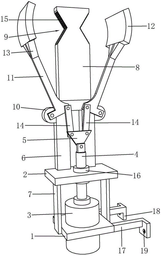
fig. 1 is a schematic structural view of a clamp for a vertical numerically controlled lathe according to the present invention;
FIG. 2 is a schematic view of the connection structure of the middle triangular transmission block and the clamping rod of the present invention;
fig. 3 is a schematic structural view of the middle storage table of the present invention.
In the figure: 1-a mounting frame; 2, fixing a plate; 3, driving a cylinder; 4-piston push rod; 5-a triangular transmission block; 6, mounting a plate; 7-reinforcing rods; 8-placing the object table; 9-V type groove; 10-ear mount; 11-a clamping bar; 12-an arc-shaped pressing plate; 13-triangular reinforcing blocks; 14-a transmission rod; 15-a triangular rack; 16-a guide sleeve; 17-a leg; 18-a mounting block; 19-mounting holes.
Detailed Description
As shown in fig. 1 to 3, for the utility model relates to a vertical anchor clamps for numerical control lathe, including mounting bracket 1, be equipped with actuating mechanism and fixed plate 2 on the mounting bracket 1, actuating mechanism drives actuating cylinder 3 and piston push rod 4 including driving actuating cylinder 3, drives actuating cylinder 3 and connects piston push rod 4, drives actuating cylinder 3 and fixes on mounting bracket 1, piston push rod 4's one end is rotated and is connected with triangular drive piece 5, is equipped with mounting panel 6 on the fixed plate 2, is equipped with anchor strut 7 between mounting bracket 1 and the fixed plate 2, has improved the joint strength between mounting bracket 1 and the fixed plate 2, and it is integrative to link to each other, and the structure is. One side of mounting panel 6 is equipped with puts thing platform 8, it all is equipped with V type groove 9 on the top surface of thing platform 8 and the bottom surface to put, 6 longitudinal symmetry distribution of mounting panel has ear seat 10, it is connected with clamping bar 11 to rotate on the ear seat 10, the one end of clamping bar 11 is equipped with arc clamp plate 12, be adapted to the surface of pipe fitting, area of contact is big, be equipped with triangle reinforcing block 13 between clamping bar 11 and the arc clamp plate 12, the joint strength between clamping bar 11 and the arc clamp plate 12 has been improved, both junctions are difficult to ftracture or the disconnection, use reliably. A transmission rod 14 is rotatably connected between the clamping rod 11 and the triangular transmission block 5, the driving cylinder 3 drives the piston push rod 4 to do telescopic motion, and the piston push rod 4 drives the transmission rod 14 to do reciprocating motion through the triangular transmission block 5, so that the inside and outside swinging of the clamping rod 11 is realized. When the pipe fitting clamping device is used, one pipe fitting is placed in the V-shaped groove 9 located above, the other pipe fitting is held by hand or lifted by other tools to be located in the V-shaped groove 9 located below, after the pipe fitting clamping device is powered on, the driving cylinder 3 drives the piston push rod 4 to retract, the transmission rod 14 is pulled back through the triangular transmission block 5, the transmission rod 14 drives the clamping rod 11 to rotate inwards, the pipe fitting is pressed in the V-shaped groove 9 by the arc-shaped pressing plate 12, the pipe fitting is not prone to freely sliding and dropping, the clamping is reliable, processing operation is facilitated, the two pipe fittings can be clamped simultaneously, the processing efficiency is improved, the pipe fitting clamping device is suitable for pipe fittings with different pipe diameters.
Triangular racks 15 are distributed in the V-shaped groove 9 at equal intervals, the roughness of the surface of the V-shaped groove 9 is increased, so that friction is improved, and the pipe fitting is not easy to freely slide after being placed and is convenient to operate. Be equipped with uide bushing 16 on the fixed plate 2, piston push rod 4 passes uide bushing 16, and uide bushing 16 plays the guide effect to piston push rod 4, avoids piston push rod 4 to take place radial drunkenness and influence the practicality of anchor clamps. The bottom symmetric distribution of mounting bracket 1 has stabilizer blade 17, is equipped with installation piece 18 on the stabilizer blade 17, is equipped with mounting hole 19 on the installation piece 18, to the interior nailing of mounting hole 19, fixes mounting bracket 1 to vertical numerical control lathe's workstation, and it is convenient to install, and stabilizer blade 17 gives mounting bracket 1 and supports, makes mounting bracket 1 break away from the workstation, guarantees sufficient operating space.
The above is only a specific embodiment of the present invention, but the technical features of the present invention are not limited thereto. Any simple changes, equivalent substitutions or modifications made on the basis of the present invention to solve the same technical problems and achieve the same technical effects are all covered by the protection scope of the present invention.