CN213437373U - Inclination-adjustable workbench for bench drilling machine - Google Patents
Inclination-adjustable workbench for bench drilling machine Download PDFInfo
- Publication number
- CN213437373U CN213437373U CN202022398893.3U CN202022398893U CN213437373U CN 213437373 U CN213437373 U CN 213437373U CN 202022398893 U CN202022398893 U CN 202022398893U CN 213437373 U CN213437373 U CN 213437373U
- Authority
- CN
- China
- Prior art keywords
- cylinder
- fixed
- rod
- base
- screw rod
- Prior art date
- Legal status (The legal status is an assumption and is not a legal conclusion. Google has not performed a legal analysis and makes no representation as to the accuracy of the status listed.)
- Expired - Fee Related
Links
- 238000005553 drilling Methods 0.000 title abstract description 19
- 230000007246 mechanism Effects 0.000 claims abstract description 10
- 238000000034 method Methods 0.000 abstract description 7
- 230000008569 process Effects 0.000 abstract description 7
- 230000007306 turnover Effects 0.000 description 3
- 238000003754 machining Methods 0.000 description 2
- 230000009286 beneficial effect Effects 0.000 description 1
- 230000007547 defect Effects 0.000 description 1
- 238000010586 diagram Methods 0.000 description 1
- 238000012986 modification Methods 0.000 description 1
- 230000004048 modification Effects 0.000 description 1
- 238000010079 rubber tapping Methods 0.000 description 1
Images

Landscapes
- Drilling And Boring (AREA)
Abstract
The utility model relates to the technical field of drilling machines, in particular to an inclination-adjustable workbench for a bench drilling machine, wherein the top surface of a base is provided with an open slot; guide rails are fixed on the left side and the right side of the open slot; the cylinder is sleeved on the rod body of the round rod; the cylinder is rotationally connected with the round rod; both ends of the round rod are fixed with sliding blocks; the slide block is embedded into the guide rail; a swing rod is fixed on the cylinder; the top surface of the base is hinged with a clamp; the bottom of the clamp is provided with a connecting plate hinged on the swing rod; a linear driving mechanism for pushing the cylinder to slide along the guide rail is fixed on the base. Use the utility model discloses the time, can realize the continuous regulation of anchor clamps angle in this structure for the drilling machine can process the hole of multiple angle, richens the processing means of drilling machine.
Description
Technical Field
The utility model relates to a drilling machine technical field, in particular to adjustable workstation of gradient that bench drill used.
Background
The drilling machine is a machine tool which mainly uses a drill to machine a hole on a workpiece. The drilling machine is simple in structure, relatively low in machining precision, capable of drilling through holes and blind holes, replacing special cutters, and capable of expanding, reaming or tapping and the like. During the machining process, a workpiece is fixed on the fixture, the drill bit rotates to move mainly, and the drill bit moves axially to move in a feeding mode to cut the workpiece. However, the workbench of the existing drilling machine can not be adjusted in angle, and the holes machined by the clamped workpiece and the main shaft do not form an angle, so that the workpiece can not be machined by the drilling machine; there is a need for further improvements to existing drill tools.
SUMMERY OF THE UTILITY MODEL
An object of the utility model is to provide an adjustable workstation of gradient that bench drill used to the defect and not enough of prior art.
In order to achieve the above object, the utility model adopts the following technical scheme:
the utility model relates to an inclination-adjustable workbench for a bench drilling machine, which comprises a machine tool body and a base fixed on the machine tool body; the top surface of the base is provided with an open slot; guide rails are fixed on the left side and the right side of the open slot; a cylinder and a round rod are arranged inside the open slot; the rod body of the round rod is matched with the inner hole of the cylinder; the cylinder is sleeved on the rod body of the round rod; the cylinder is rotationally connected with the round rod; the two ends of the round rod are both fixed with sliding blocks; the sliding block is matched with the guide rail; the sliding block is embedded into the guide rail; a swing rod is fixed on the cylinder; the top surface of the base is hinged with a clamp; the bottom of the clamp is provided with a connecting plate hinged on the swing rod; and a linear driving mechanism for pushing the cylinder to slide along the guide rail is fixed on the base.
Furthermore, the linear driving mechanism comprises a screw rod nut, a screw rod and a motor fixed on the base; the feed screw nut is fixed on the cylinder; the internal thread of the screw rod nut is matched with the external thread of the screw rod; the screw rod is in threaded connection with the screw rod nut; one end of the screw rod is rotatably connected with the base; the other end of the screw rod is fixed on the output end of the motor.
Furthermore, a protractor for measuring the swing angle of the clamp is fixed on the base.
After the structure is adopted, the utility model discloses beneficial effect does: the utility model relates to an inclination adjustable workbench for a bench drill, the top surface of a base is provided with an open slot; guide rails are fixed on the left side and the right side of the open slot; a cylinder and a round rod are arranged inside the open slot; the rod body of the round rod is matched with the inner hole of the cylinder; the cylinder is sleeved on the rod body of the round rod; the cylinder is rotationally connected with the round rod; both ends of the round rod are fixed with sliding blocks; the slide block is matched with the guide rail; the slide block is embedded into the guide rail; a swing rod is fixed on the cylinder; the top surface of the base is hinged with a clamp; the bottom of the clamp is provided with a connecting plate hinged on the swing rod; a linear driving mechanism for pushing the cylinder to slide along the guide rail is fixed on the base. When the utility model is used, a workpiece to be processed is clamped and fixed on the clamp, the linear driving mechanism drives the round rod to slide along the length direction of the guide rail through the cylinder after driving, the cylinder pushes the clamp to turn over through the swing rod in the process of linear sliding, and the clamp adjusts the angle; can realize the continuous regulation of anchor clamps angle in this structure for the drilling machine can process the hole of multiple angle, richenes the means of processing of drilling machine.
Drawings
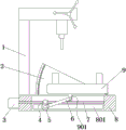
Fig. 1 is a schematic structural diagram of the present invention;
FIG. 2 is an internal structural view of the base;
description of reference numerals:
1. a machine tool body; 2. a protractor; 3. a motor; 4. a feed screw nut; 5. a cylinder; 6. a swing rod;
7. a screw rod; 8. a base; 801. a guide rail; 802. an open slot; 9. a clamp; 901. a connecting plate;
10. a round bar; 11. a slide block.
Detailed Description
The present invention will be further described with reference to the accompanying drawings.
As shown in fig. 1 to 2, the inclination adjustable workbench for a bench drill of the present invention comprises a machine tool body 1 and a base 8 fixed on the machine tool body 1; the top surface of the base 8 is provided with an open slot 802; guide rails 801 are fixed on the left side and the right side of the open slot 802; a cylinder 5 and a round rod 10 are arranged in the open slot 802; the rod body of the round rod 10 is matched with the inner hole of the cylinder 5; the cylinder 5 is sleeved on the rod body of the round rod 10; the cylinder 5 is rotationally connected with a round rod 10; two ends of the round rod 10 are both fixed with sliding blocks 11; the slide block 11 is matched with the guide rail 801; the slide block 11 is embedded in the guide rail 801; a swing rod 6 is fixed on the cylinder 5; the top surface of the base 8 is hinged with a clamp 9; the clamp 9 is not essentially different from the prior art and is therefore not described in detail; the bottom of the clamp 9 is provided with a connecting plate 901 hinged on the swing rod 6; a linear driving mechanism for pushing the cylinder 5 to slide along the guide rail 801 is fixed on the base 8; a workpiece to be processed is clamped and fixed on a clamp 9, a linear driving mechanism drives a round rod 10 to slide along the length direction of a guide rail 801 through a cylinder 5 after driving, the clamp 9 is pushed to turn over through a swing rod 6 in the process of linear sliding of the cylinder 5, and the angle of the clamp 9 is adjusted; can realize the continuous regulation of 9 angles of anchor clamps in this structure for the drilling machine can process the hole of multiple angle, richens the means of processing of drilling machine.
As a preferred mode of the present invention, the linear driving mechanism includes a screw nut 4, a screw 7 and a motor 3 fixed on a base 8; the feed screw nut 4 is fixed on the cylinder 5; the internal thread of the screw nut 4 is matched with the external thread of the screw 7; the screw rod 7 is in threaded connection with the screw rod nut 4; one end of the screw rod 7 is rotatably connected with the base 8; the other end of the screw rod 7 is fixed on the output end of the motor 3; after the motor 3 drives the screw rod 7 to rotate, the screw rod nut 4 and the cylinder 5 are pushed to slide along the length direction of the guide rail 801.
As an optimized mode of the present invention, the base 8 is fixed with the protractor 2 for measuring the swing angle of the clamp 9.
When the utility model is used, a workpiece to be processed is clamped and fixed on the clamp, the motor drives the lead screw to rotate, then the lead screw nut and the cylinder are pushed to slide along the length direction of the guide rail, the cylinder pushes the clamp to turn over through the swing rod in the process of linear sliding, and the clamp adjusts the angle; can realize the continuous regulation of anchor clamps angle in this structure for the drilling machine can process the hole of multiple angle, richenes the means of processing of drilling machine.
The above is only the preferred embodiment of the present invention, so all the equivalent changes or modifications made by the structure, features and principles in accordance with the claims of the present invention are included in the claims of the present invention.
Claims (3)
1. The utility model provides an adjustable workstation of gradient that bench drill used which characterized in that: the machine tool comprises a machine tool body (1) and a base (8) fixed on the machine tool body (1); the top surface of the base (8) is provided with an open slot (802); guide rails (801) are fixed on the left side and the right side of the open slot (802); a cylinder (5) and a round rod (10) are arranged in the opening groove (802); the rod body of the round rod (10) is matched with the inner hole of the cylinder (5); the cylinder (5) is sleeved on the rod body of the round rod (10); the cylinder (5) is rotationally connected with the round rod (10); both ends of the round rod (10) are fixed with sliding blocks (11); the sliding block (11) is matched with the guide rail (801); the sliding block (11) is embedded into the guide rail (801); a swing rod (6) is fixed on the cylinder (5); the top surface of the base (8) is hinged with a clamp (9); the bottom of the clamp (9) is provided with a connecting plate (901) hinged on the swing rod (6); and a linear driving mechanism for pushing the cylinder (5) to slide along the guide rail (801) is fixed on the base (8).
2. An adjustable inclination table for a bench drill according to claim 1 wherein: the linear driving mechanism comprises a screw rod nut (4), a screw rod (7) and a motor (3) fixed on a base (8); the feed screw nut (4) is fixed on the cylinder (5); the internal thread of the screw rod nut (4) is matched with the external thread of the screw rod (7); the screw rod (7) is in threaded connection with the screw rod nut (4); one end of the screw rod (7) is rotatably connected with the base (8); the other end of the screw rod (7) is fixed on the output end of the motor (3).
3. An adjustable inclination table for a bench drill according to claim 1 wherein: and the base (8) is fixedly provided with a protractor (2) for measuring the swing angle of the clamp (9).
Priority Applications (1)
| Application Number | Priority Date | Filing Date | Title |
|---|---|---|---|
| CN202022398893.3U CN213437373U (en) | 2020-10-26 | 2020-10-26 | Inclination-adjustable workbench for bench drilling machine |
Applications Claiming Priority (1)
| Application Number | Priority Date | Filing Date | Title |
|---|---|---|---|
| CN202022398893.3U CN213437373U (en) | 2020-10-26 | 2020-10-26 | Inclination-adjustable workbench for bench drilling machine |
Publications (1)
| Publication Number | Publication Date |
|---|---|
| CN213437373U true CN213437373U (en) | 2021-06-15 |
Family
ID=76294622
Family Applications (1)
| Application Number | Title | Priority Date | Filing Date |
|---|---|---|---|
| CN202022398893.3U Expired - Fee Related CN213437373U (en) | 2020-10-26 | 2020-10-26 | Inclination-adjustable workbench for bench drilling machine |
Country Status (1)
| Country | Link |
|---|---|
| CN (1) | CN213437373U (en) |
Cited By (2)
| Publication number | Priority date | Publication date | Assignee | Title |
|---|---|---|---|---|
| CN118789009A (en) * | 2024-09-13 | 2024-10-18 | 杭州鄂达精密机电科技有限公司 | A tool for machining side holes of valve body shaft |
| CN118893233A (en) * | 2024-09-25 | 2024-11-05 | 麦孚思科技(苏州)有限公司 | Intelligent machine tool for parts processing and operation method thereof |
-
2020
- 2020-10-26 CN CN202022398893.3U patent/CN213437373U/en not_active Expired - Fee Related
Cited By (3)
| Publication number | Priority date | Publication date | Assignee | Title |
|---|---|---|---|---|
| CN118789009A (en) * | 2024-09-13 | 2024-10-18 | 杭州鄂达精密机电科技有限公司 | A tool for machining side holes of valve body shaft |
| CN118789009B (en) * | 2024-09-13 | 2025-02-25 | 杭州鄂达精密机电科技有限公司 | A tool for machining side holes of valve body shaft |
| CN118893233A (en) * | 2024-09-25 | 2024-11-05 | 麦孚思科技(苏州)有限公司 | Intelligent machine tool for parts processing and operation method thereof |
Similar Documents
| Publication | Publication Date | Title |
|---|---|---|
| CN209021706U (en) | A tool turning lathe | |
| CN205437779U (en) | Compound lathe drilling equipment of section of thick bamboo wall drilling | |
| CN110181086B (en) | A horizontal multi-axis drilling machine | |
| CN107486732A (en) | Rotary type hole drilling device for workpieces | |
| CN203409303U (en) | Graduated deep hole drilling machine | |
| CN219616767U (en) | Inner hole machining device | |
| CN209206982U (en) | A kind of plate drilling machine fixes device with hand-rail type Bidirectional clamping | |
| CN219598193U (en) | Alloy drill thread groove grooving device | |
| CN214488893U (en) | Radial drill is used in spot facing work | |
| CN209364166U (en) | A kind of hardware precision part drilling machine for machining | |
| CN222134152U (en) | Drilling machine for machining brake pump shell | |
| CN212635107U (en) | Drilling positioning fixture and drilling machine tool | |
| CN219617175U (en) | Positioning structure and machining equipment | |
| CN215356328U (en) | Multi-angle air hole bench drilling machine | |
| CN221716311U (en) | A CNC lathe machining fixture | |
| CN222288881U (en) | A deep hole processing device | |
| CN220659940U (en) | Automatic drilling machine convenient to change drill bit | |
| CN222754934U (en) | A machine tool clamping platform | |
| CN223997803U (en) | Numerical control lathe with locate function | |
| CN223476362U (en) | A workpiece punching fixture for a lathe tool holder | |
| CN219212290U (en) | Automatic two-axis drilling structure for lathe | |
| CN221773909U (en) | Laser nozzle accessories processing device | |
| CN219358680U (en) | Marine piston inclined hole processingequipment | |
| CN223477209U (en) | Ceramic sphere numerical control grinding lathe | |
| CN220880561U (en) | Vertical lathe for machining connecting frame |
Legal Events
| Date | Code | Title | Description |
|---|---|---|---|
| GR01 | Patent grant | ||
| GR01 | Patent grant | ||
| CF01 | Termination of patent right due to non-payment of annual fee | ||
| CF01 | Termination of patent right due to non-payment of annual fee |
Granted publication date: 20210615 |