CN213415179U - Carrier lifting mechanism - Google Patents
Carrier lifting mechanism Download PDFInfo
- Publication number
- CN213415179U CN213415179U CN202022525539.2U CN202022525539U CN213415179U CN 213415179 U CN213415179 U CN 213415179U CN 202022525539 U CN202022525539 U CN 202022525539U CN 213415179 U CN213415179 U CN 213415179U
- Authority
- CN
- China
- Prior art keywords
- belt line
- carrier
- bottom plate
- plate
- lifting mechanism
- Prior art date
- Legal status (The legal status is an assumption and is not a legal conclusion. Google has not performed a legal analysis and makes no representation as to the accuracy of the status listed.)
- Active
Links
Images

Landscapes
- Automatic Assembly (AREA)
Abstract
The utility model discloses a carrier lifting mechanism, which is used for a carrier on a jacking conveying line and comprises a welding frame, a lifting cylinder, a synchronous lifter, a belt line bottom plate and a belt line; the welding frame is rectangular, the lifting cylinder is used for jacking the belt line bottom plate, penetrates through the middle of welding and is fixed on the welding frame through a pair of cylinder fixing plates, and the synchronous lifter is fixedly arranged on the upper surface of the welding frame; the belt line bottom plate is arranged on the synchronous lifter, and a pair of parallel vertical plates are integrally formed at the positions, close to the two sides, of the upper surface of the belt line bottom plate; the belt line is used for conveying the carrier to the conveying line, is arranged on the outer side face of the vertical plate and is driven by a motor fixed on a bottom plate of the belt line. The utility model discloses a carrier elevating system, when the double-deck transfer chain of cooperation used, can realize the automatic cycle circulation of carrier, promoted work efficiency greatly.
Description
Technical Field
The utility model relates to a jacking device technical field, concretely relates to carrier elevating system.
Background
In the processing production of electronic equipment, a conveying line is needed to transport carrier plates loaded with workpieces, and various processing devices are arranged on the conveying line, so that the flow automatic processing is realized, and the production efficiency is greatly improved. In the existing production process, a plurality of workpieces to be machined are often placed in a carrier, and a series of operation processes such as corresponding machining, assembling, testing and detecting are carried out on a conveying line, so that finished workpieces are finally obtained.
In the processing and production process, the carrier needs to be jacked to a certain height through a specific jacking device, so that the grabbing mechanism can grab the carrier conveniently. In the prior art, the carrier jacking device has the defects of relatively complex structure, low working efficiency and the like.
SUMMERY OF THE UTILITY MODEL
The to-be-solved technical problem of the utility model is to provide a carrier elevating system, when this carrier elevating system cooperation double-deck transfer chain used, can realize the automatic cycle circulation of carrier, promoted work efficiency greatly.
In order to solve the technical problem, the utility model provides a following technical scheme:
the utility model provides a carrier lifting mechanism, which is used for lifting a carrier on a conveying line, and comprises a welding frame, a lifting cylinder, a synchronous lifter, a belt line bottom plate and a belt line;
the welding frame is rectangular, the lifting cylinder is used for jacking the belt line bottom plate, penetrates through the middle of welding and is fixed on the welding frame through a pair of cylinder fixing plates, and the synchronous lifter is fixedly arranged on the upper surface of the welding frame; the belt line bottom plate is arranged on the synchronous lifter, and a pair of parallel vertical plates are integrally formed at the positions, close to the two sides, of the upper surface of the belt line bottom plate; the belt line is used for conveying the carrier to the conveying line, is arranged on the outer side face of the vertical plate and is driven by a motor fixed on a bottom plate of the belt line.
Furthermore, a foot cup is respectively installed at four corners of the welding frame.
Furthermore, a plurality of linear bearings are installed on the surface of the welding frame, guide shafts penetrate through the linear bearings, and guide holes matched with the guide shafts are formed in the positions, corresponding to the belt line bottom plate, of the belt line bottom plate.
Furthermore, a square hole is formed in the middle of the belt line bottom plate, and a jacking plate is fixedly mounted on the square hole; the lower surface of the jacking plate is provided with a floating joint matched with a piston rod of the lifting cylinder, and the lifting cylinder jacks the jacking plate through the floating joint.
Further, the belt line includes drive shaft, a plurality of belt line tow pulleys and the PU belt of suit on the belt line tow pulley, the belt line tow pulley is installed equidistantly on the lateral surface of riser, drive shaft connection is between one of them pair of belt line tow pulleys.
Furthermore, a tensioning block is further installed on the inner side face of the vertical plate, a long installation groove is formed in the tensioning block, and the belt line tug at the tail end is adjustably fixed on the vertical plate through the installation groove.
Furthermore, a guide profile is fixed on the belt line bottom plate and positioned on the outer side of the vertical plate.
Further, a microswitch is further arranged on the bottom plate of the belt line.
Compared with the prior art, the beneficial effects of the utility model reside in that:
1. the utility model discloses a carrier elevating system, it receives the empty utensil back that the lower floor's transfer chain transmitted, and the lift cylinder starts, with the height of belt line and carrier jacking to the upper transfer chain together, places the material back on empty carrier, and the belt line starts, carries the carrier again on the transfer chain. When this carrier elevating system cooperates the use of double-deck transfer chain, can realize the automatic cycle circulation of carrier, promote work efficiency greatly.
2. The utility model discloses a carrier elevating system, through set up synchronous riser on the welding frame, rely on the linkage cooperation between gear and the rack in the synchronous riser, guarantee a plurality of strong points synchronous lifting, and then realized the steady lift of belt line bottom plate.
Drawings
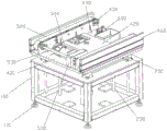
Fig. 1 is a schematic structural view of a carrier lifting mechanism according to an embodiment of the present invention;
FIG. 2 is a schematic view of a portion of the carrier lift mechanism of FIG. 1;
the reference numbers in the figures illustrate: 100. welding a frame; 110. a foot cup; 210. a synchronous lifter; 220. a linear bearing; 230. a guide shaft; 300. a lifting cylinder; 310. a cylinder fixing plate; 320. a floating joint; 400. a belt line bottom plate; 410. a square hole; 420. a jacking plate; 430. a vertical plate; 440. reinforcing ribs; 450. a tensioning block; 460. a guide profile; 510. a belt line tugboat; 520. a PU belt; 530. a drive shaft; 540. a motor; 550. a motor cover; 600. a micro switch.
Detailed Description
The present invention is further described with reference to the following drawings and specific embodiments so that those skilled in the art can better understand the present invention and can implement the present invention, but the embodiments are not to be construed as limiting the present invention.
Unless defined otherwise, all technical and scientific terms used herein have the same meaning as commonly understood by one of ordinary skill in the art to which this invention belongs. The terminology used in the description of the invention herein is for the purpose of describing particular embodiments only and is not intended to be limiting of the invention. As used herein, the term "and/or" includes any and all combinations of one or more of the associated listed items.
As described in the background art, in the processing and production process of electronic products, a carrier needs to be lifted to a certain height by a specific lifting device, so as to facilitate the grabbing mechanism to grab. In the prior art, the carrier jacking device has the defects of relatively complex structure, low working efficiency and the like.
In order to solve the problem, the utility model provides a carrier elevating system, including welding frame 100, lift cylinder 300, synchronous lift 210, belt line bottom plate 400 and belt line.
Referring to fig. 1-2, the welding stand 100 is rectangular and has a foot cup 110 mounted at each of the four corners of the bottom thereof. The lifting cylinder 300 passes through the middle of the welding and is fixed to the welding stand 100 by a pair of cylinder fixing plates 310. The synchronous lifter 210 is fixedly installed on the upper surface of the welding stand 100, and has four supporting points.
The belt line bottom plate 400 is disposed on the synchronous lifter 210, a square hole 410 is formed in the middle of the belt line bottom plate, a lifting plate 420 is fixedly installed on the square hole 410, and the lifting plate 420 is an inverted U-shaped lifting plate 420 in this embodiment. The lower surface of the lifting plate 420 is provided with a floating joint 320 matched with the piston rod of the lifting cylinder 300, and the lifting cylinder 300 lifts the lifting plate 420 through the floating joint 320.
A pair of parallel vertical plates 430 are integrally formed on the upper surface of the belt line bottom plate 400 near both sides, and a plurality of reinforcing ribs 440 are preferably provided between the inner sides of the vertical plates 430 and the belt line bottom plate 400 to improve the strength of the vertical plates 430. The belt line comprises a driving shaft 530, a plurality of belt line tuggers 510 (including a driving wheel and a driven wheel) and a PU belt 520 sleeved on the belt line tuggers 510, wherein the belt line tuggers 510 are equidistantly installed on the outer side surface of the vertical plate 430, and the driving shaft 530 is connected between a pair of the belt line tuggers 510 (the driving wheel). A motor 540 is further fixed on the belt line bottom plate 400, and the motor 540 drives the driving shaft 530 to rotate through a chain, so as to drive the belt line to rotate. The motor 540 is preferably provided with a motor cover 550.
A tensioning block 450 is further installed on the inner side surface of the vertical plate 430, an elongated installation groove is formed in the tensioning block 450, and the belt line tug 510 at the extreme end is adjustably fixed on the vertical plate 430 through the installation groove. The PU belt 520 may be tensioned by adjusting the installation position of the endmost belt line tug 510. Preferably, a guide profile 460 is further fixed on the belt line bottom plate 400 at the outer side of the vertical plate 430.
The utility model discloses an in the embodiment, the surface mounting of welding frame 100 has a plurality of linear bearing 220, and the cross-under has guiding axle 230 among this linear bearing 220, and the position that belt line bottom plate 400 corresponds is equipped with the guiding hole that matches with guiding axle 230 to can play the effect of direction to the lift of belt line bottom plate 400, improve the stability of lift.
The utility model discloses in, still be equipped with a plurality of micro-gap switches 600 on belt line bottom plate 400 for the start-up and the closing of control belt line, in order to realize the transmission of carrier.
The utility model discloses a carrier elevating system's working process does:
when the carrier lifting mechanism of the utility model is used in cooperation with a double-layer conveying line, when an empty carrier is conveyed by a lower-layer conveying line, a belt line is started to move the empty carrier to the central position of the jacking mechanism; then, the lifting cylinder 300 is started to drive the belt line and the idle tool to rise to the same height of the upper-layer conveying line; then, materials are put into the empty carriers, and the belt line is started again to convey the carriers to the upper-layer conveying line; finally, the lifting cylinder 300 is activated again so that the belt line is lowered to the initial position.
The above-mentioned embodiments are merely preferred embodiments for fully illustrating the present invention, and the scope of the present invention is not limited thereto. Equivalent substitutes or changes made by the technical personnel in the technical field on the basis of the utility model are all within the protection scope of the utility model. The protection scope of the present invention is subject to the claims.
Claims (8)
1. A carrier lifting mechanism is characterized by comprising a welding frame, a lifting cylinder, a synchronous lifter, a belt line bottom plate and a belt line;
the welding frame is rectangular, the lifting cylinder is used for jacking the belt line bottom plate, penetrates through the middle of welding and is fixed on the welding frame through a pair of cylinder fixing plates, and the synchronous lifter is fixedly arranged on the upper surface of the welding frame; the belt line bottom plate is arranged on the synchronous lifter, and a pair of parallel vertical plates are integrally formed at the positions, close to the two sides, of the upper surface of the belt line bottom plate; the belt line is used for conveying the carrier to the conveying line, is arranged on the outer side face of the vertical plate and is driven by a motor fixed on a bottom plate of the belt line.
2. The carrier lifting mechanism of claim 1, wherein a foot cup is mounted at each of four corners of the welding frame.
3. The carrier lifting mechanism according to claim 1, wherein a plurality of linear bearings are mounted on a surface of the welding frame, a guide shaft penetrates through the linear bearings, and a guide hole matched with the guide shaft is formed in a position corresponding to the belt line base plate.
4. The carrier lifting mechanism of claim 1, wherein a square hole is formed in the middle of the belt line base plate, and a lifting plate is fixedly mounted on the square hole; the lower surface of the jacking plate is provided with a floating joint matched with a piston rod of the lifting cylinder, and the lifting cylinder jacks the jacking plate through the floating joint.
5. The carrier lifting mechanism according to claim 1, wherein the belt line comprises a driving shaft, a plurality of belt line tuggers and a PU belt sleeved on the belt line tuggers, the belt line tuggers are mounted on the outer side surface of the vertical plate at equal intervals, and the driving shaft is connected between a pair of the belt line tuggers.
6. The carrier lifting mechanism according to claim 5, wherein a tensioning block is further mounted on an inner side surface of the vertical plate, the tensioning block is provided with an elongated mounting groove, and the endmost belt line tug is adjustably fixed on the vertical plate through the mounting groove.
7. The carrier lifting mechanism of claim 1, wherein a guide profile is further fixed on the belt line bottom plate outside the vertical plate.
8. The carrier lifting mechanism of claim 1, wherein a micro switch is further disposed on the belt line base plate.
Priority Applications (1)
| Application Number | Priority Date | Filing Date | Title |
|---|---|---|---|
| CN202022525539.2U CN213415179U (en) | 2020-11-04 | 2020-11-04 | Carrier lifting mechanism |
Applications Claiming Priority (1)
| Application Number | Priority Date | Filing Date | Title |
|---|---|---|---|
| CN202022525539.2U CN213415179U (en) | 2020-11-04 | 2020-11-04 | Carrier lifting mechanism |
Publications (1)
| Publication Number | Publication Date |
|---|---|
| CN213415179U true CN213415179U (en) | 2021-06-11 |
Family
ID=76249399
Family Applications (1)
| Application Number | Title | Priority Date | Filing Date |
|---|---|---|---|
| CN202022525539.2U Active CN213415179U (en) | 2020-11-04 | 2020-11-04 | Carrier lifting mechanism |
Country Status (1)
| Country | Link |
|---|---|
| CN (1) | CN213415179U (en) |
Cited By (2)
| Publication number | Priority date | Publication date | Assignee | Title |
|---|---|---|---|---|
| CN114261670A (en) * | 2021-11-30 | 2022-04-01 | 华晓精密工业(苏州)有限公司 | Chain type lifting and conveying integrated equipment |
| CN114523673A (en) * | 2022-01-14 | 2022-05-24 | 李志康 | Device for processing high-strength joint of belt and joint method thereof |
-
2020
- 2020-11-04 CN CN202022525539.2U patent/CN213415179U/en active Active
Cited By (4)
| Publication number | Priority date | Publication date | Assignee | Title |
|---|---|---|---|---|
| CN114261670A (en) * | 2021-11-30 | 2022-04-01 | 华晓精密工业(苏州)有限公司 | Chain type lifting and conveying integrated equipment |
| CN114261670B (en) * | 2021-11-30 | 2024-05-17 | 华晓精密工业(苏州)有限公司 | Chain type lifting and conveying integrated equipment |
| CN114523673A (en) * | 2022-01-14 | 2022-05-24 | 李志康 | Device for processing high-strength joint of belt and joint method thereof |
| CN114523673B (en) * | 2022-01-14 | 2023-10-20 | 李志康 | Device and method for processing high-strength joint of belt |
Similar Documents
| Publication | Publication Date | Title |
|---|---|---|
| CN210764160U (en) | Compact lifting combined fork | |
| CN112027550B (en) | A laborsaving type handling device for material transport uses | |
| CN112693819B (en) | Electric automobile battery package is changed and is used digital lift | |
| CN111620040A (en) | roller conveyor | |
| CN213567953U (en) | Encoder line body | |
| CN216272891U (en) | Reciprocating roller elevator | |
| CN210764128U (en) | Cut fork lift's supporter and cut fork lift | |
| CN211225940U (en) | Movable elevator | |
| CN220787117U (en) | Conveying device suitable for tray quick reflux | |
| CN108861505B (en) | Oblique lifting and conveying device for shaft parts | |
| CN218371504U (en) | Lifting device for glass production | |
| CN216444936U (en) | Self-loading lifting platform | |
| CN218215231U (en) | Automatic crystal discharging support device | |
| CN209792913U (en) | automatic tubular product transport mechanism that adsorbs of magnet | |
| CN219689268U (en) | Tray detaching device for forklift multi-layer tray | |
| CN220885977U (en) | Tray conveying structure for automatic assembly line | |
| CN205526190U (en) | Lift conveying system | |
| CN209352509U (en) | A kind of stacking hoistable platform | |
| CN214113764U (en) | Rigid chain lifting transfer machine | |
| CN220449693U (en) | Novel guide rail type lifter | |
| CN220485255U (en) | Material lifting machine | |
| CN221369346U (en) | Vegetable planting dish stacking device | |
| CN218663642U (en) | Jacking transplanter | |
| CN220866442U (en) | Goods handling lifting machine | |
| CN216807320U (en) | Full-automatic cavity grid plate hacking machine |
Legal Events
| Date | Code | Title | Description |
|---|---|---|---|
| GR01 | Patent grant | ||
| GR01 | Patent grant |