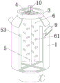
High-performance anticorrosive material mixing equipment
Technical Field
The utility model relates to an anticorrosive material processing technology field specifically is a high performance anticorrosive material mixing equipment.
Background
The anticorrosive material is a material for inhibiting the chemical corrosion and the electrochemical corrosion of an anticorrosive object, common anticorrosive materials in installation engineering mainly comprise various organic and inorganic coatings, glass fiber reinforced plastics, rubber products, inorganic plates and the like, and in the process of manufacturing and processing the anticorrosive material, special anticorrosive material mixing equipment is required to be used for uniformly mixing the anticorrosive material, however, most of the existing anticorrosive material mixing equipment carries out single-stage rotating stirring and mixing on different anticorrosive materials through a stirring rod, the mixing efficiency of the anticorrosive material is low, and the anticorrosive material is easy to adhere to the inner wall of a mixing frame, so that the stirring and mixing efficiency of the mixing equipment on the anticorrosive material is influenced.
SUMMERY OF THE UTILITY MODEL
An object of the utility model is to provide a high performance anticorrosive material mixing equipment to solve the problem that proposes in the above-mentioned background art.
In order to achieve the above object, the utility model provides a following technical scheme: a high-performance anticorrosive material mixing device comprises a mixing outer frame, wherein a support frame is fixedly sleeved in the middle of the outer surface of the mixing outer frame, the top end of the mixing outer frame is fixedly connected with a connecting frame, a driving mechanism is fixedly arranged in the connecting frame, a cleaning mechanism and a stirring rod are fixedly arranged at the bottom end of the driving mechanism, and the cleaning mechanism and the stirring rod are both positioned in the mixing outer frame;
the driving mechanism comprises a mechanism outer frame, a supporting bottom plate is fixedly connected to the upper end of the inner wall of the mechanism outer frame, a driving shaft is inserted into the middle of the supporting bottom plate in a rotating mode, a connecting plate is fixedly connected to the bottom end of the driving shaft, connecting shafts are perpendicularly connected to the two sides of the bottom end of the connecting plate, a driving gear is sleeved on the bottom of each connecting shaft in a rotating mode, the driving gears are symmetrically distributed, an annular tooth groove matched with the driving gear in use is formed in the lower side of the inner surface of the mechanism outer frame, and the two groups of driving gears.
As a preferred technical scheme of the utility model, actuating mechanism passes through the fixed joint of mechanism frame in the link, supporting baseplate's top fixed mounting has driving motor, driving motor's output pass supporting baseplate's bottom and with the top fixed connection of drive shaft.
As a preferred technical scheme of the utility model, the puddler is provided with two sets ofly, and is two sets of the top of puddler corresponds respectively with drive gear's bottom middle part fixed connection, the surface equidistance fixedly connected with multiunit stirring nose bar of puddler.
As the utility model discloses a preferred technical scheme, clearance mechanism includes the connecting rod, the top of connecting rod and the bottom middle part of connecting plate are connected perpendicularly, the bottom fixedly connected with cross link of connecting rod, the equal fixed mounting in top four corners department of cross link has clean scraper blade, the outer wall of clean scraper blade and the inner wall contact of mixing frame.
As an optimal technical scheme of the utility model, the length of connecting rod is greater than the length of puddler.
As a preferred technical scheme of the utility model, the bottom of the blending outer frame is of a funnel-shaped structure, the bottom end of the blending outer frame is fixedly connected with a discharging pipe, and the discharging pipe is provided with a flow control valve;
and symmetrically distributed feeding pipes are fixedly inserted into the upper part of the uniformly mixing outer frame.
Compared with the prior art, the beneficial effects of the utility model are that:
1. the utility model discloses, have the puddler of multiunit stirring nose bar through the setting to the actuating mechanism is used in the cooperation, can carry out multistage stirring to the anticorrosive material of difference, has improved whole mixing equipment greatly to anticorrosive material's stirring mixing efficiency.
2. Through setting up clearance mechanism to the cooperation uses actuating mechanism, can realize that four clean scrapers of group carry out scraper blade formula cleanness to the inner wall of mixing frame, effectively prevents that anticorrosive material from attaching to the inner wall of mixing frame, thereby has further improved whole mixing equipment and to anticorrosive material's stirring mixing efficiency.
Drawings
FIG. 1 is a schematic structural view of the present invention;
FIG. 2 is a schematic connection diagram of a middle part structure of the present invention;
FIG. 3 is an enlarged view of the point A in FIG. 2 according to the present invention;
fig. 4 is a cross-sectional view of the connection of the middle part structure of the present invention.
In the figure: 1. uniformly mixing the outer frame; 2. a support frame; 3. a connecting frame; 4. a drive mechanism; 5. a cleaning mechanism; 6. a stirring rod; 7. a discharge pipe; 8. a flow control valve; 9. a feed pipe; 10. a drive motor; 41. a mechanism outer frame; 411. an annular gullet; 42. a support base plate; 43. a drive shaft; 44. a connecting plate; 441. a connecting shaft; 45. a drive gear; 51. a connecting rod; 52. a cross-shaped connecting frame; 53. a cleaning blade; 61. the convex rod is stirred.
Detailed Description
The technical solutions in the embodiments of the present invention will be described clearly and completely with reference to the accompanying drawings in the embodiments of the present invention, and it is obvious that the described embodiments are only some embodiments of the present invention, not all embodiments. Based on the embodiments in the present invention, all other embodiments obtained by a person skilled in the art without creative work belong to the protection scope of the present invention.
Referring to fig. 1-4, the present invention provides a technical solution: a high-performance anticorrosive material mixing device comprises a mixing outer frame 1, a support frame 2 is fixedly sleeved in the middle of the outer surface of the mixing outer frame 1, a connecting frame 3 is fixedly connected to the top end of the mixing outer frame 1, a driving mechanism 4 is fixedly arranged in the connecting frame 3, a cleaning mechanism 5 and a stirring rod 6 are fixedly arranged at the bottom end of the driving mechanism 4, the cleaning mechanism 5 and the stirring rod 6 are both positioned in the mixing outer frame 1, the inner wall of the mixing outer frame 1 is effectively cleaned in a scraper manner by the cleaning mechanism 5, anticorrosive materials are prevented from being attached to the inner wall of the mixing outer frame 1, and various anticorrosive materials can be effectively stirred and mixed by the stirring rod 6; the bottom of the blending outer frame 1 is of a funnel-shaped structure, the bottom end of the blending outer frame 1 is fixedly connected with a discharge pipe 7, a flow control valve 8 is arranged on the discharge pipe 7, and the flow control valve 8 is controlled to control the blended anticorrosive material to flow out of the discharge pipe 7; the upper portion of mixing frame 1 is fixed to be inserted and is equipped with inlet pipe 9 that is the symmetric distribution, makes things convenient for the user to annotate different anticorrosive material from inlet pipe 9 to mixing frame 1.
The driving mechanism 4 comprises a mechanism outer frame 41, a supporting bottom plate 42 is fixedly connected to the upper end of the inner wall of the mechanism outer frame 41, a driving shaft 43 is rotatably inserted in the middle of the supporting bottom plate 42, a connecting plate 44 is fixedly connected to the bottom end of the driving shaft 43, connecting shafts 441 are vertically connected to two sides of the bottom end of the connecting plate 44, driving gears 45 are rotatably sleeved at the bottoms of the two groups of connecting shafts 441, the two groups of driving gears 45 are symmetrically distributed, annular tooth sockets 411 matched with the driving gears 45 are formed in the lower side of the inner surface of the mechanism outer frame 41, and the two groups of driving gears; the driving mechanism 4 is fixedly clamped in the connecting frame 3 through the mechanism outer frame 41, the driving motor 10 is fixedly installed at the top end of the supporting bottom plate 42, the output end of the driving motor 10 penetrates through the bottom end of the supporting bottom plate 42 and is fixedly connected with the top end of the driving shaft 43, the driving shaft 43 is driven to rotate in the middle of the supporting bottom plate 42 by starting the driving motor 10, so that two groups of driving gears 45 connected with the connecting plate 44 are driven to revolve around the driving shaft 43, the driving gears 45 on two sides are meshed with the annular tooth grooves 411 while the driving gears 45 revolve around, and the driving gears 45 on two sides rotate around the connecting shaft 441.
Puddler 6 is provided with two sets ofly, the top of two sets of puddlers 6 corresponds respectively and drive gear 45's bottom middle part fixed connection, the surface equidistance fixedly connected with multiunit stirring convex rod 61 of puddler 6, when two sets of drive gear 45 use drive shaft 43 to revolve as the center, drive two sets of puddler 6 that correspond respectively and rotate, carry out the one-level stirring to different anticorrosive material in the mixing frame 1, both sides drive gear 45 uses connecting axle 441 to carry out the rotation and drive the multiunit stirring convex rod 61 of puddler 6 surface and carry out the second grade stirring to different anticorrosive material simultaneously, through the multistage stirring to different anticorrosive material, whole mixing equipment has improved anticorrosive material's stirring mixing efficiency greatly.
Cleaning mechanism 5 includes connecting rod 51, the top of connecting rod 51 and the bottom middle part of connecting plate 44 are connected perpendicularly, the bottom fixedly connected with cross link 52 of connecting rod 51, the equal fixed mounting in top four corners department of cross link 52 has cleaning scraper blade 53, cleaning scraper blade 53's the outer wall and the inner wall contact of mixing frame 1, rotation through connecting plate 44, drive connecting rod 51 and rotate, thereby four groups of cleaning scraper blade 53 of connecting with cross link 52 rotate, and then it is clean to the scraper blade formula of the inner wall of mixing frame 1 to have realized four groups of cleaning scraper blade 53, prevent effectively that anticorrosive material from adhering to the inner wall at mixing frame 1, thereby whole mixing equipment has further improved the stirring mixing efficiency of anticorrosive material.
The length of the connecting rod 51 is larger than that of the stirring rod 6, so that the material is stirred and mixed uniformly and the inner wall scraper is cleaned without interference.
The working principle is as follows: the utility model relates to a high performance anticorrosive material mixing equipment, not only can realize the multistage stirring to different anticorrosive material, improved whole mixing equipment to anticorrosive material's stirring mixing efficiency, simultaneously can be to the scraper blade type cleanness of the inner wall of mixing frame 1, prevent effectively that anticorrosive material from adhering to the inner wall of mixing frame 1, thereby further improved whole mixing equipment to anticorrosive material's stirring mixing efficiency, during the use, fill different anticorrosive material into mixing frame 1 through inlet pipe 9, subsequently start driving motor 10, drive shaft 43 rotates at the middle part of supporting baseplate 42, thereby drive two sets of drive gear 45 that are connected with connecting plate 44 revolve around drive shaft 43 as the center, when drive gear 45 revolves around, the drive gear 45 and the annular tooth's socket 411 of both sides mesh, thereby reach both sides drive gear 45 and use connecting axle 441 as the center and carry out the rotation, when the two groups of driving gears 45 revolve around the driving shaft 43, the two corresponding groups of stirring rods 6 are respectively driven to rotate, different anticorrosive materials in the blending outer frame 1 are subjected to primary stirring, meanwhile, the two driving gears 45 on the two sides rotate around the connecting shaft 441 to drive the multiple groups of stirring convex rods 61 on the outer surfaces of the stirring rods 6 to perform secondary stirring on the different anticorrosive materials, and the stirring and blending efficiency of the whole blending device on the anticorrosive materials is greatly improved by performing multi-stage stirring on the different anticorrosive materials, wherein the connecting rod 51 is driven to rotate through the rotation of the connecting plate 44, so that the four groups of cleaning scrapers 53 connected with the cross connecting frame 52 are driven to rotate, the scraper-type cleaning of the inner walls of the blending outer frame 1 by the four groups of cleaning scrapers 53 is further realized, the anticorrosive materials are effectively prevented from being attached to the inner walls of the blending outer frame 1, and the stirring efficiency of the whole blending, after different anticorrosive materials are stirred and mixed uniformly, the uniformly mixed anticorrosive materials are controlled to flow out of the discharge pipe 7 by controlling the flow control valve 8.
Although embodiments of the present invention have been shown and described, it will be appreciated by those skilled in the art that changes, modifications, substitutions and alterations can be made in these embodiments without departing from the principles and spirit of the invention, the scope of which is defined in the appended claims and their equivalents.