Nylon film production leftover bits and pieces recovery unit
Technical Field
The embodiment of the utility model provides a nylon film production technical field, concretely relates to nylon film production leftover bits and pieces recovery unit.
Background
The nylon film is a very tough film, has good transparency, good luster, high tensile strength and tensile strength, good heat resistance, cold resistance, oil resistance and organic solvent resistance, excellent wear resistance and puncture resistance, is softer, has excellent oxygen resistance, has poor barrier property to water vapor, has high moisture absorption and moisture permeability and poor heat sealability, and is suitable for packaging hard articles such as greasy food, meat products, fried food, vacuum packaged food, steamed food and the like. However, when nylon films are used, the nylon films are often cut into different sizes to package products, a large amount of leftovers are generated in the cutting process, so that in order to avoid waste, people start waste utilization, and waste materials are recycled, which is commonly called as 'scrap repair and waste utilization', and the leftovers, leftover materials, waste products and the like which can be utilized in production and living consumption are collected, sorted, processed and reformed and then converted into a series of useful materials.
However, in actual use, most of the recovery devices on the market are in a separated state, leftovers are manually collected at each blanking port, are moved to a special stirring place and are stirred, and are moved to a next recovery place, so that manpower is needed, time is consumed, and the leftovers occupy a lot.
SUMMERY OF THE UTILITY MODEL
Therefore, the embodiment of the utility model provides a nylon film production leftover bits and pieces recovery unit to solve among the prior art because the recovery unit separation and the problem that leads to waste time and energy and take the space.
In order to achieve the above object, the embodiment of the present invention provides the following technical solutions: a nylon film production leftover recovery device comprises a conveying table, wherein a first support is arranged at the top of the conveying table, a conveying cylinder is sleeved on the outer side of the first support, the bottom of the conveying table is fixedly connected with a placement box, a stirring blade is arranged inside the placement box, a rotating rod is fixedly connected to the top of the stirring blade, the rotating rod is connected with the conveying table, a funnel opening is formed in the bottom of the placement box, a cup-shaped pipeline is arranged at the bottom of the funnel opening, one end of the cup-shaped pipeline is fixedly connected with the funnel opening, a recovery box is fixedly connected to the other end of the cup-shaped pipeline, a collection device is arranged on one side of the funnel opening, and an extrusion device is arranged inside the recovery box;
the collecting device comprises a fixing plate, the fixing plate is arranged at the bottom of the placing box, a round hole is formed in the surface of the fixing plate, one side of the fixing plate is connected with the collecting plate, a brace is fixedly connected to the bottom of the collecting plate, the brace penetrates through the fixing plate through the round hole and extends to the outside of the fixing plate, a spring is arranged at the bottom of the fixing plate, one end of the spring is fixedly connected with the fixing plate, and the other end of the spring is fixedly connected with the collecting plate;
the extrusion device comprises an electric telescopic rod, the electric telescopic rod is connected inside the recycling box, an extrusion plate is fixedly connected to the output end of the electric telescopic rod, and a baffle is arranged at the bottom of the recycling box.
Further, one side of a conveying section of thick bamboo is provided with the second support, the outside cover of second support is equipped with the pivot, the outside cover of pivot is equipped with cutting blade, the top of conveying platform is provided with the rectangular channel, the rectangular channel vertical distribution is in cutting blade's below, the inner wall fixedly connected with filter screen of flare opening.
Further, a plurality of micropores have been seted up on the surface of baffle, the quantity of dwang sets up to 4, the quantity of stirring piece sets up to 4.
Further, the number of the cutting blades is set to 2, the number of the rectangular grooves is set to 2, the number of the second brackets is set to 2, and the number of the rotating shafts is set to 2.
Further, one side of baffle is provided with the air exhauster, stir garrulous blade and make by the metal material, one side of conveying platform is the arc.
The embodiment of the utility model provides a have following advantage:
1. through settling a series of devices such as case, compared with the prior art, the leftover bits and pieces drop and stir garrulous blade, stir garrulous blade and be driven by the dwang, the dwang passes through the motor and rotates, thereby make and stir garrulous blade continuous rotation, the leftover bits and pieces that will drop, lead to through stirring into the piece all, brace among the rethread collection device drives the collecting plate, send the leftover bits and pieces into the flare opening by the filter screen, begin to collect in the source of leftover bits and pieces, collection device and conveying platform fixed connection are integrative, the cambered surface that the leftover bits and pieces pass through the conveying platform is because gravity drops downwards, need not the manpower and collects, also be convenient for process after stirring and utilize.
2. Through the extrusion device, compare with prior art, the motor is connected to the telescopic link at top in the recovery box, and telescopic link downstream drives the stripper plate and presses the rigor reality of leftover bits and pieces for the volume of leftover bits and pieces is reduced, is convenient for deposit.
Drawings
In order to more clearly illustrate the embodiments of the present invention or the technical solutions in the prior art, the drawings used in the description of the embodiments or the prior art will be briefly described below. It should be apparent that the drawings in the following description are merely exemplary, and that other embodiments can be derived from the drawings provided by those of ordinary skill in the art without inventive effort.
The structure, ratio, size and the like shown in the present specification are only used for matching with the content disclosed in the specification, so as to be known and read by people familiar with the technology, and are not used for limiting the limit conditions which can be implemented by the present invention, so that the present invention has no technical essential significance, and any structure modification, ratio relationship change or size adjustment should still fall within the scope which can be covered by the technical content disclosed by the present invention without affecting the efficacy and the achievable purpose of the present invention.
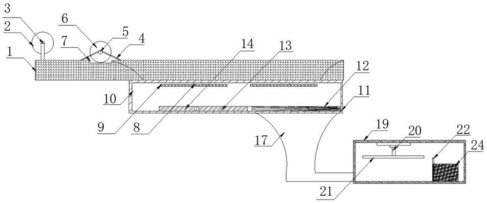
Fig. 1 is a schematic view of the overall structure of the present invention.
Fig. 2 is a schematic top view of the present invention.
Fig. 3 is a schematic view of the baffle structure of the present invention.
Fig. 4 is a schematic structural view of the crushing blade of the present invention.
Fig. 5 is a schematic structural view of the collecting device of the present invention;
in the figure: 1. a transfer table; 2. a first bracket; 3. a transfer drum; 4. a second bracket; 5. a rotating shaft; 6. a cutting blade; 7. a rectangular groove; 8. rotating the rod; 9. crushing the blades; 10. a placement box; 11. a funnel opening; 12. A filter screen; 13. a fixing plate; 14. bracing; 15. a circular hole; 16. a spring 16; 17. a cup-shaped conduit; 18. a Z-shaped pipeline; 19. a recycling bin; 20. an electric telescopic rod; 21. a pressing plate; 22. a baffle plate; 23. Micropores; 24. an exhaust fan.
Detailed Description
The present invention is described in terms of specific embodiments, and other advantages and benefits of the present invention will become apparent to those skilled in the art from the following disclosure. Based on the embodiments in the present invention, all other embodiments obtained by a person skilled in the art without creative work belong to the protection scope of the present invention.
Referring to the attached figures 1-5 of the specification, the recycling device for leftovers in the production of the nylon film comprises a conveying table 1, the top of the conveying table 1 is provided with a first support 2, the outer side of the first support 2 is sleeved with a conveying cylinder 3, the bottom of the conveying table 1 is fixedly connected with a placing box 10, a stirring 9 blade is arranged inside the placing box 10, the top of the mincing blade 9 is fixedly connected with a rotating rod 8, the rotating rod 8 is connected with the conveying table 1, a funnel opening 11 is arranged at the bottom of the placing box 10, a cup-shaped pipeline 17 is arranged at the bottom of the funnel opening 11, one end of the cup-shaped pipeline 17 is fixedly connected with the funnel opening 11, the other end of the cup-shaped pipeline 17 is fixedly connected with a recovery box 19, a collecting device is arranged on one side of the funnel opening 11, and an extruding device is arranged inside the recycling box 19;
the collecting device comprises a fixing plate 13, the fixing plate 13 is arranged at the bottom of the placing box 10, a round hole 25 is formed in the surface of the fixing plate 13, a collecting plate 14 is connected to one side of the fixing plate 13, a brace 15 is fixedly connected to the bottom of the collecting plate 14, the brace 15 penetrates through the fixing plate 13 through the round hole 25 and extends to the outside of the fixing plate 13, a spring 16 is arranged at the bottom of the fixing plate 13, one end of the spring 16 is fixedly connected with the fixing plate 13, and the other end of the spring 16 is fixedly connected with the collecting plate 14;
the extrusion device comprises an electric telescopic rod 20, the electric telescopic rod 20 is connected inside a recycling box 19, an extrusion plate 21 is fixedly connected to the output end of the electric telescopic rod 20, and a baffle is arranged at the bottom of the recycling box 19.
The implementation scenario is specifically as follows: the conveying table 1 and the second support 3 are matched for use, so that the conveying cylinder 3 can continuously rotate under the action of a motor, a nylon film is continuously rolled into the conveying cylinder 3, leftovers generated in the conveying process of the nylon film are completely crushed by using the crushing blade 9 in the arranging box 10 and finally fall to the bottom of the arranging box 10, the collecting device arranged at the bottom of the arranging box 10 is used by matching the brace 15 with the collecting plate 14, the fallen leftovers are pushed to the funnel mouth 11, the collecting plate 14 is reset again by matching the spring 16 with the fixed plate 13 for use, the leftovers are pushed continuously, fall into the cup-shaped pipeline 17 after falling from the funnel mouth 11 and fall into the extruding device at the top of the recycling box 19, the extruding plate is driven downwards through the electric telescopic rod 20, and the leftovers fragments are pressed tightly, thereby saving the storing space of the leftovers, and being convenient for the extrusion of the extrusion device through the baffle plate 22.
One side of conveying cylinder 3 is provided with second support 4, the outside cover of second support 4 is equipped with pivot 5, the outside cover of pivot 5 is equipped with cutting blade 6, the top of conveying platform 1 is provided with rectangular channel 7, rectangular channel 7 vertical distribution is in cutting blade 6's below to in order to become the appointed shape with the film cutting.
The inner wall of the funnel opening 11 is fixedly connected with a filter screen 12 so as to prevent impurities from being mixed when leftovers are recovered.
The surface of the baffle is provided with a plurality of micropores 23 so as to facilitate the operation of an exhaust fan 24.
The quantity of dwang 8 sets up to 4, the quantity of stirring bits 9 sets up to four to cut into the piece with the leftover bits.
The number of the cutting blades 6 is set to 2, the number of the rectangular grooves 7 is set to 2, the number of the second brackets 4 is set to 2, and the number of the rotating shafts 5 is set to 2, so that the conveying table 1 is prevented from being cut during cutting.
An exhaust fan 24 is provided on one side of the baffle to facilitate the drawing of scrap pieces into the recovery tank 19.
The stirring crushing blade 9 is made of metal material, and one side of the conveying table 1 is arc-shaped, so that the lower corner of the conveying table falls to the placing box 10.
The implementation scenario is specifically as follows: the nylon film conveys the in-process, set up pivot 5 and cutting blade 6's cooperation through on the second support 4 and use, cut into required shape with the nylon film, use through rectangular channel 7, can make cutting blade 6 can not cut bad conveying platform 1 when cutting, use through the arcwall face of conveying platform 1 afterbody, the leftover bits are collected in the bottom because gravity drops, use through air exhauster 24, can inhale the collection box 19 with falling into the leftover bits piece of cup type pipeline 17, use through micropore 23 when using air exhauster 24, can avoid inhaling into the leftover bits piece and receive wind-force influence, circle round in collection box 19, the extrusion of being more convenient for, do not influence air exhauster 24 again simultaneously and use.
The utility model discloses use as follows: the nylon film slowly moves from right to left on the conveying table 1, when the nylon film reaches the position of the rectangular groove 7, the second support 4 is connected with the rotating shaft 5 to drive the cutting blade 6 to rotate, the cutting blade 6 cuts the nylon film into a shape with a specified width, the nylon film with the specified width is rolled in by the conveying cylinder 3, the cut leftovers fall downwards through the arc surface of the conveying table 1 due to gravity, the leftovers fall to the crushing blade 9, the crushing blade 9 is driven by the rotating rod 8, the rotating rod 8 rotates through the motor, so that the crushing blade 9 continuously rotates, and the fallen leftovers are stirred into fragments; the collecting plate 14 is driven by a brace 15 in the collecting device, the brace 15 is controlled by an electric operating machine, leftover fragments are sent into the funnel mouth 11 through the filter screen 12, impurities which accidentally fall can be isolated by using the filter screen 12, the impurities are prevented from being mixed in the leftover fragments, the quality of a recovered product is influenced, after one wave of collection, the collecting plate is reset by using the elastic force of a spring 16 between the fixing plate 13 and the collecting plate 14, next wave of collection is carried out, the leftover fragments fall to a cup-shaped pipeline 17 from the funnel mouth 11, and are sucked into the recovery box 19 in the cup-shaped pipeline 17 by an exhaust fan 24 in the recovery box 19; through the extrusion device, the motor is connected to the electric telescopic handle 20 at top in the collection box 19, electric telescopic handle 20 downstream, it is strict with leftover bits and pieces pressure to drive stripper plate 21, use through micropore 23 when using air exhauster 24, the extrusion of being more convenient for, do not influence air exhauster 24 again simultaneously and must use, recovery unit is connected with cutting device like this, needn't waste time and energy again collect at each feed opening, still add in this device in addition and stir garrulous and compaction these two major steps, make the volume of leftover bits and pieces reduce, be convenient for deposit.
Although the invention has been described in detail with respect to the general description and the specific embodiments, it will be apparent to those skilled in the art that modifications and improvements can be made based on the invention. Therefore, such modifications and improvements are intended to be within the scope of the invention as claimed.
In the present specification, the terms "upper", "lower", "left", "right", "middle", and the like are used for clarity of description, and are not intended to limit the scope of the present invention, and changes or modifications in the relative relationship may be made without substantial changes in the technical content.