CN213380658U - Production equipment is managed in accurate side for steel construction - Google Patents
Production equipment is managed in accurate side for steel construction Download PDFInfo
- Publication number
- CN213380658U CN213380658U CN202022180271.3U CN202022180271U CN213380658U CN 213380658 U CN213380658 U CN 213380658U CN 202022180271 U CN202022180271 U CN 202022180271U CN 213380658 U CN213380658 U CN 213380658U
- Authority
- CN
- China
- Prior art keywords
- unit
- fixedly connected
- motor
- connecting piece
- screw rod
- Prior art date
- Legal status (The legal status is an assumption and is not a legal conclusion. Google has not performed a legal analysis and makes no representation as to the accuracy of the status listed.)
- Active
Links
Images


Abstract
The utility model discloses a production facility is managed in accurate side for steel construction, which comprises a bod, organism top front side fixed mounting has clamping unit, organism both sides wall symmetry is equipped with the unit of polishing, organism top rear side fixed mounting has spacing unit, spacing unit one side is equipped with adjustable support unit, organism top rear side is opened and is equipped with the spout, through the cushioning effect of spring between the sliding plate in the clamping structure, reduces among the clamping unit impact force between sliding plate and the thick side pipe outer wall to mutual damage is too big when preventing to collide between sliding plate and the thick side pipe outer wall in the clamping unit, makes the clamping unit life of production facility is managed in accurate side for the steel construction increase.
Description
Technical Field
The utility model relates to a production technical field is managed with accurate side to the steel construction, specifically is a production facility is managed with accurate side to steel construction.
Background
The square tube is a steel tube with equal side length, is formed by rolling strip steel through technological treatment, and is formed by unpacking, flattening, curling and welding the strip steel to form a circular tube, rolling the circular tube into a square tube, and then shearing the square tube into required length.
In square tube production, it is common to handle the thick square tube rolled from the round tube to make the thick square tube become a precision square tube, where polishing is just an important processing step, and when polishing, it is common to clamp the thick square tube.
But when current precision square tube production facility for steel construction was tight thick square tube, press from both sides tight structure and can collide with thick square tube, therefore press from both sides tight structure and produce mutual damage with thick square tube.
SUMMERY OF THE UTILITY MODEL
Technical problem to be solved by the utility model
An object of the utility model is to provide a production facility is managed in accurate side for steel construction to when solving current production facility is managed in accurate side for steel construction and pressing from both sides thick square pipe tight, press from both sides tight structure and can collide with thick square pipe, therefore press from both sides tight structure and thick square pipe and produce the problem of mutual damage.
Technical scheme
In order to achieve the above object, the utility model provides a technical scheme does:
the utility model provides a production facility is managed in accurate side for steel construction, includes the organism, organism top front side fixed mounting has clamping unit, organism both sides wall symmetry is equipped with the unit of polishing, organism top rear side fixed mounting spacing unit, spacing unit one side is equipped with adjustable support unit, organism top rear side is opened and is equipped with the spout.
Preferably, the clamping unit comprises a plurality of first motors, a first screw rod is arranged at the output end of each first motor, the first screw rod penetrates through the first supporting plate, a screw rod sleeve is in threaded connection with the tail end of the first screw rod, sliding plates are arranged on the sleeves in the direction away from the first motors, the sliding plates are symmetrically arranged on one sides of the second supporting plates in a sliding mode, and springs are arranged between the sliding plates.
Preferably, the bottom ends of the first supporting plate and the second supporting plate are fixedly connected with the machine body, and the rear wall of the second supporting plate is slidably connected with the sliding plate.
Preferably, the polishing unit comprises a second motor, one side of the second motor penetrates through the side wall of the machine body, one side of the second motor is connected with an electric telescopic rod through a rotor, and a polishing wheel unit is arranged at one end of the electric telescopic rod.
Preferably, the grinding wheel unit comprises a motor III, the bottom end of the motor III penetrates through the connecting piece I through a rotor, the bottom end of the motor III is connected with the grinding wheel through the rotor, and the bottom end of the grinding wheel is connected with the connecting piece II through a bearing.
Preferably, one side of the connecting piece is fixedly connected with the top end of one side of the electric telescopic rod, and one side of the connecting piece is fixedly connected with the bottom end of one side of the electric telescopic rod.
Preferably, the limiting unit comprises a rotating button, one side of the rotating button is fixedly connected with a second screw rod, the outer wall of the second screw rod is in threaded connection with a nut, an L-shaped supporting piece is penetrated through one side of the second screw rod, one side of the second screw rod is connected with a push plate bearing, and the bottom end of the L-shaped supporting piece is fixedly connected with the machine body.
Preferably, the adjustable supporting unit comprises a fourth motor, the four sides of the motor penetrate through the L-shaped connecting piece through the rotor, the four sides of the motor are connected with a third screw rod through the rotor, the three outer walls of the screw rod are connected with three threads of the supporting plate, the three sides of the screw rod are connected with the square plate through the bearing, the three sides of the supporting plate are fixedly connected with the square connecting piece, one side of the square connecting piece is fixedly connected with the baffle, and the three bottom ends of the supporting plate are connected with the sliding grooves in a matched mode.
Preferably, one side of the L-shaped connecting piece is fixedly connected with the square plate, and the bottom end of the square plate is fixedly connected with the side wall of the machine body.
Advantageous effects
Adopt the technical scheme provided by the utility model, compare with prior art, have following beneficial effect:
through the cushioning effect of spring between the sliding plate among the clamping structure, reduce the clamping unit in the sliding plate with thick side impact between the pipe outer wall to mutual damage is too big when preventing between the clamping unit sliding plate and thick side pipe outer wall, makes the steel construction increase with the clamping unit life of accurate square pipe production facility.
Drawings
FIG. 1 is a schematic structural view of the present invention;
FIG. 2 is a schematic structural view of the clamping unit of the present invention;
FIG. 3 is a schematic view of the structure of the polishing unit of the present invention;
FIG. 4 is a schematic view of the polishing wheel unit of the present invention;
FIG. 5 is a schematic view of the structure of the limiting unit of the present invention;
fig. 6 is a schematic view of the structure of the adjustable supporting unit of the present invention.
In the figure: 1. the machine body comprises a machine body, 2, a clamping unit, 21, a first motor, 22, a first support plate, 23, a first screw rod, 24, a screw rod sleeve, 25, a sliding plate, 26, a support plate, 27, a spring, 3, a polishing unit, 31, a second motor, 32, an electric telescopic rod, 33, a polishing wheel unit, 331, a third motor, 332, a first connecting piece, 333, a polishing wheel, 334, a second connecting piece, 4, a limiting unit, 41, a rotating button, 42, a second screw rod, 43, a nut, 44, an L-shaped supporting piece, 45, a pushing plate, 5, an adjustable supporting unit, 51, a fourth motor, 52, an L-shaped connecting piece, 53, a third screw rod, 54, a third support plate, 55, a square plate, 56, a square connecting piece, 57, a baffle, 6 and a.
Detailed Description
The technical solution in the embodiments of the present invention will be clearly and completely described below with reference to the drawings in the embodiments of the present invention, and it is obvious that the described embodiments are only some embodiments of the present invention, rather than all embodiments, and all other embodiments obtained by a person of ordinary skill in the art without creative work belong to the protection scope of the present invention based on the embodiments of the present invention.
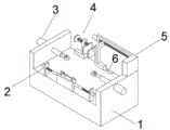
An embodiment, please refer to fig. 1-6, the utility model provides a technical scheme, a precision side pipe production facility for steel construction, including organism 1, 1 top front side fixed mounting of organism has clamping unit 2, 1 both sides wall symmetry of organism is equipped with the unit of polishing 3, 1 top rear side fixed mounting of organism has spacing unit 4, spacing unit 4 one side is equipped with adjustable support unit 5, 1 top rear side of organism is seted up and is equipped with spout 6.
In an embodiment, referring to fig. 2, the clamping unit 2 includes a plurality of first motors 21, the first screws 23 are disposed at output ends of the first motors 21, the first screws 23 penetrate through the first support plates 22, the ends of the first screws 23 are connected with screw sleeves 24 in a threaded manner, the sleeves 24 are provided with sliding plates 25 in a direction away from the first motors, the sliding plates 25 are symmetrically slidably disposed on one side of the second support plates 26, and springs 27 are disposed between the sliding plates 25.
In this embodiment, the threaded connection length of the first screw 23 and the screw sleeve 24 is longer than the sliding length of the single sliding plate 25 on the second support plate 26, and the second support plate 26 limits the sliding plate 25 so that the sliding plate 25 can only slide laterally.
In an embodiment, referring to fig. 1-2, the bottom ends of the first supporting plates 22 are fixedly connected to the machine body 1, the bottom ends of the second supporting plates 26 are fixedly connected to the machine body 1, and the rear walls of the second supporting plates 26 are slidably connected to the sliding plate 25.
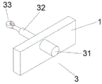
In an embodiment, referring to fig. 3, the polishing unit 3 includes a second motor 31, one side of the second motor 31 penetrates through a sidewall of the machine body 1, one side of the second motor 31 is connected to an electric telescopic rod 32 through a rotor, and one end of the electric telescopic rod 32 is provided with a polishing wheel unit 33.
In an embodiment, referring to fig. 4, the grinding wheel unit 33 includes a third motor 331, a bottom end of the third motor 331 penetrates through the first connecting member 332 through a rotor, a bottom end of the third motor 331 is connected with the grinding wheel 333 through the rotor, and a bottom end of the grinding wheel 333 is connected with the second connecting member 334 through a bearing.
In this embodiment, the first connecting member 332 is not in contact with the grinding wheel 333, and the second connecting member 334 is not in contact with the grinding wheel 333, so that no resistance is generated on the grinding wheel 333 during grinding.
In an embodiment, referring to fig. 3 to 4, one side of the first connecting member 332 is fixedly connected to the top end of one side of the electric telescopic rod 32, and one side of the second connecting member 334 is fixedly connected to the bottom end of one side of the electric telescopic rod 32.
In an embodiment, referring to fig. 1 and 5, the limiting unit 4 includes a rotating button 41, one side of the rotating button 41 is fixedly connected to a second lead screw 42, an outer wall of the second lead screw 42 is in threaded connection with a nut 43, one side of the second lead screw 42 penetrates through an L-shaped supporting member 44, one side of the second lead screw 42 is in bearing connection with a pushing plate 45, and a bottom end of the L-shaped supporting member 44 is fixedly connected to the machine body 1.
Limiting unit 4 adopts manual regulation in this example, compares the flexibility ratio higher with ordinary automatically regulated, and the fine setting effect is better.
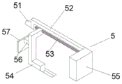
In an embodiment, referring to fig. 6, the adjustable supporting unit 5 includes a motor four 51, one side of the motor four 51 penetrates through an L-shaped connecting member 52 through a rotor, one side of the motor four 51 is connected with a screw rod three 53 through the rotor, an outer wall of the screw rod three 53 is in threaded connection with a supporting plate three 54, one side of the screw rod three 53 is connected with a square plate 55 through a bearing, one side of the supporting plate three 54 is fixedly connected with a square connecting member 56, one side of the square connecting member 56 is fixedly connected with a baffle 57, and a bottom end of the supporting plate three 54 is in matched connection with the chute 6.
In an embodiment, referring to fig. 1 and fig. 6, one side of the L-shaped connecting member 52 is fixedly connected to the square plate 55, and the bottom end of the square plate 55 is fixedly connected to the side wall of the machine body 1.
The utility model discloses a theory of operation:
during the use, at first, according to thick side's pipe width, it rotates to drive three 53 of lead screw through motor four 51 in adjustable supporting element 5, it slides along spout 6 to drive three 54 of backup pad through three 53 of lead screw, it removes to drive square connecting piece 56 through three 54 of backup pad, it removes to drive baffle 57 through square connecting piece 56, it is spacing for the first time to make baffle 57 carry out thick side's pipe, it rotates to drive two 42 of lead screw through rotating button 41, it removes to drive slurcam 45 through two 42 of lead screw, rethread nut 43 rotates, fix two 42 of lead screw, it is spacing to make slurcam 4 carry out the second to thick side's pipe, thereby it can not produce about skew to make thick side's pipe press from both sides tightly, and then it is more.
Then, a first motor 21 in the clamping unit 2 drives a first screw rod 23 to rotate, a first screw rod 23 drives a screw rod sleeve 24 to move, the screw rod sleeve 24 drives a sliding plate 25 to slide along the rear side of a second support plate 26, the sliding plate 25 clamps the thick square pipe, and a spring 27 is compressed under the action of the sliding plate 25, so that the sliding plate 25 is buffered, the sliding plate 25 is slowly contacted with the thick square pipe, and the sliding plate 25 is prevented from being excessively damaged when being contacted with the outer wall of the thick square pipe.
Finally, the electric telescopic rod 32 is driven to move through the second motor 31, the polishing wheel unit 33 is driven to be in contact with the outer wall of the rough pipe through the electric telescopic rod 32, and the polishing wheel is driven to rotate 333 through the third motor 331, so that the wheel rotates 333 to polish the outer wall of the rough pipe.
Although embodiments of the present invention have been shown and described, it will be appreciated by those skilled in the art that changes, modifications, substitutions and alterations can be made in these embodiments without departing from the principles and spirit of the invention, the scope of which is defined in the appended claims and their equivalents.
Claims (9)
1. The utility model provides a precision side's pipe production facility for steel construction, includes organism (1), its characterized in that: organism (1) top front side fixed mounting has clamping unit (2), organism (1) both sides wall symmetry is equipped with unit (3) of polishing, organism (1) top rear side fixed mounting limit unit (4), limit unit (4) one side is equipped with adjustable support element (5), organism (1) top rear side is opened and is equipped with spout (6).
2. The equipment for producing the precise square tubes for the steel structures according to claim 1 is characterized in that the clamping unit (2) comprises a plurality of first motors (21), first lead screws (23) are arranged at the output ends of the first motors (21), the first lead screws (23) penetrate through first supporting plates (22), lead screw sleeves (24) are in threaded connection with the tail ends of the first lead screws (23), sliding plates (25) are arranged on the sleeves (24) in the direction away from the first motors, the sliding plates (25) are symmetrically arranged on one sides of second supporting plates (26) in a sliding mode, and springs (27) are arranged between the sliding plates (25).
3. The production equipment for the precise square tubes for the steel structure according to claim 2 is characterized in that the bottom ends of the first support plates (22) are fixedly connected with the machine body (1), the bottom ends of the second support plates (26) are fixedly connected with the machine body (1), and the rear walls of the second support plates (26) are slidably connected with the sliding plates (25).
4. The production equipment of the precise square tube for the steel structure according to claim 1 is characterized in that the grinding unit (3) comprises a second motor (31), one side of the second motor (31) penetrates through the side wall of the machine body (1), one side of the second motor (31) is connected with an electric telescopic rod (32) through a rotor, and one end of the electric telescopic rod (32) is provided with a grinding wheel unit (33).
5. The production equipment of the precise square tubes for the steel structures is characterized in that the grinding wheel unit (33) comprises a motor III (331), the bottom end of the motor III (331) penetrates through a connecting piece I (332) through a rotor, the bottom end of the motor III (331) is connected with a grinding wheel (333) through the rotor, and the bottom end of the grinding wheel (333) is connected with a connecting piece II (334) through a bearing.
6. The production equipment for the precise square tubes for the steel structure according to claim 5 is characterized in that one side of the first connecting piece (332) is fixedly connected with the top end of one side of the electric telescopic rod (32), and one side of the second connecting piece (334) is fixedly connected with the bottom end of one side of the electric telescopic rod (32).
7. The production equipment of the precise square tube for the steel structure according to claim 1, wherein the limiting unit (4) comprises a rotating button (41), one side of the rotating button (41) is fixedly connected with a second screw rod (42), the outer wall of the second screw rod (42) is in threaded connection with a nut (43), one side of the second screw rod (42) penetrates through an L-shaped supporting piece (44), one side of the second screw rod (42) is in bearing connection with a pushing plate (45), and the bottom end of the L-shaped supporting piece (44) is fixedly connected with the machine body (1).
8. The production equipment of the precise square tube for the steel structure according to claim 1 is characterized in that the adjustable supporting unit (5) comprises a motor four (51), one side of the motor four (51) penetrates through the L-shaped connecting piece (52) through a rotor, one side of the motor four (51) is connected with a screw rod three (53) through the rotor, the outer wall of the screw rod three (53) is in threaded connection with a supporting plate three (54), one side of the screw rod three (53) is connected with the square plate (55) through a bearing, one side of the supporting plate three (54) is fixedly connected with the square connecting piece (56), one side of the square connecting piece (56) is fixedly connected with the baffle plate (57), and the bottom end of the supporting plate three (54) is in matched connection with the sliding groove (6).
9. The production equipment for the precise square tubes for the steel structure according to claim 8 is characterized in that one side of the L-shaped connecting piece (52) is fixedly connected with the square plate (55), and the bottom end of the square plate (55) is fixedly connected with the side wall of the machine body (1).
Priority Applications (1)
| Application Number | Priority Date | Filing Date | Title |
|---|---|---|---|
| CN202022180271.3U CN213380658U (en) | 2020-09-29 | 2020-09-29 | Production equipment is managed in accurate side for steel construction |
Applications Claiming Priority (1)
| Application Number | Priority Date | Filing Date | Title |
|---|---|---|---|
| CN202022180271.3U CN213380658U (en) | 2020-09-29 | 2020-09-29 | Production equipment is managed in accurate side for steel construction |
Publications (1)
| Publication Number | Publication Date |
|---|---|
| CN213380658U true CN213380658U (en) | 2021-06-08 |
Family
ID=76184928
Family Applications (1)
| Application Number | Title | Priority Date | Filing Date |
|---|---|---|---|
| CN202022180271.3U Active CN213380658U (en) | 2020-09-29 | 2020-09-29 | Production equipment is managed in accurate side for steel construction |
Country Status (1)
| Country | Link |
|---|---|
| CN (1) | CN213380658U (en) |
Cited By (1)
| Publication number | Priority date | Publication date | Assignee | Title |
|---|---|---|---|---|
| CN114055262A (en) * | 2021-11-30 | 2022-02-18 | 芜湖赢诺液压科技有限公司 | Excircle polishing equipment |
-
2020
- 2020-09-29 CN CN202022180271.3U patent/CN213380658U/en active Active
Cited By (1)
| Publication number | Priority date | Publication date | Assignee | Title |
|---|---|---|---|---|
| CN114055262A (en) * | 2021-11-30 | 2022-02-18 | 芜湖赢诺液压科技有限公司 | Excircle polishing equipment |
Similar Documents
| Publication | Publication Date | Title |
|---|---|---|
| CN211332908U (en) | Supporting appliance for flange | |
| CN110328304B (en) | Automatic wire stripping and bending device for power industry | |
| CN213380658U (en) | Production equipment is managed in accurate side for steel construction | |
| CN211003922U (en) | Simple and easy portable storage device of cable | |
| CN210160930U (en) | Quick burnishing device in bar part surface | |
| CN210914772U (en) | Device for quickly straightening cable | |
| CN211701271U (en) | A device of skinning fast for cable | |
| CN211565543U (en) | Tilting angle clamping and positioning tool for polishing cambered surface of motor sheet metal shell | |
| CN210131951U (en) | Full-automatic mechanical plate rolling machine with adjustable machining length | |
| CN209143313U (en) | A kind of coiled strip tensioner of battery electrode piece roller | |
| CN211104233U (en) | Efficient cutting equipment for machining power pipe | |
| CN210102861U (en) | Intermittent type formula pipe fitting material feeding unit | |
| CN215847366U (en) | Quick deckle edge clearing device of panel processing usefulness | |
| CN215200684U (en) | High-precision large-diameter shaft workpiece supporting sliding table for machine tool | |
| CN213561019U (en) | Accurate grinding and cutting integrated equipment for hexagonal steel bar | |
| CN212070099U (en) | Aluminium alloy punching equipment | |
| CN109720906B (en) | Copper pipe's uncoiling device | |
| CN211072949U (en) | Stainless steel band edge grinding device is with fixed frock | |
| CN209393771U (en) | A kind of horizontal thicker steel plate venner reeling device | |
| CN212419872U (en) | Cutting device convenient to adjust length for processing disc snail | |
| CN217799149U (en) | Perforating device is used in precision machinery equipment parts machining | |
| CN217942399U (en) | Automatic push rod seat welding device for automobile braking | |
| CN110899422A (en) | Aluminum profile bending device | |
| CN220516110U (en) | Fixing tool for machining stainless steel fittings | |
| CN220717312U (en) | Bending device for steel structure machining |
Legal Events
| Date | Code | Title | Description |
|---|---|---|---|
| GR01 | Patent grant | ||
| GR01 | Patent grant |