CN213358770U - Energy-saving and water-saving device for building - Google Patents
Energy-saving and water-saving device for building Download PDFInfo
- Publication number
- CN213358770U CN213358770U CN202020928158.6U CN202020928158U CN213358770U CN 213358770 U CN213358770 U CN 213358770U CN 202020928158 U CN202020928158 U CN 202020928158U CN 213358770 U CN213358770 U CN 213358770U
- Authority
- CN
- China
- Prior art keywords
- water
- frame
- saving
- rainwater
- water outlet
- Prior art date
- Legal status (The legal status is an assumption and is not a legal conclusion. Google has not performed a legal analysis and makes no representation as to the accuracy of the status listed.)
- Expired - Fee Related
Links
- XLYOFNOQVPJJNP-UHFFFAOYSA-N water Substances O XLYOFNOQVPJJNP-UHFFFAOYSA-N 0.000 claims abstract description 159
- NJPPVKZQTLUDBO-UHFFFAOYSA-N novaluron Chemical compound C1=C(Cl)C(OC(F)(F)C(OC(F)(F)F)F)=CC=C1NC(=O)NC(=O)C1=C(F)C=CC=C1F NJPPVKZQTLUDBO-UHFFFAOYSA-N 0.000 claims abstract description 16
- 239000008399 tap water Substances 0.000 abstract description 4
- 235000020679 tap water Nutrition 0.000 abstract description 4
- 238000011010 flushing procedure Methods 0.000 description 4
- 239000012535 impurity Substances 0.000 description 4
- 238000001914 filtration Methods 0.000 description 3
- 239000002351 wastewater Substances 0.000 description 2
- 230000004075 alteration Effects 0.000 description 1
- 230000009286 beneficial effect Effects 0.000 description 1
- 238000004134 energy conservation Methods 0.000 description 1
- 238000005516 engineering process Methods 0.000 description 1
- 238000000034 method Methods 0.000 description 1
- 238000012986 modification Methods 0.000 description 1
- 230000004048 modification Effects 0.000 description 1
- 239000010865 sewage Substances 0.000 description 1
- 238000006467 substitution reaction Methods 0.000 description 1
- 210000002700 urine Anatomy 0.000 description 1
- 238000005406 washing Methods 0.000 description 1
- 239000002699 waste material Substances 0.000 description 1
Images


Classifications
-
- Y—GENERAL TAGGING OF NEW TECHNOLOGICAL DEVELOPMENTS; GENERAL TAGGING OF CROSS-SECTIONAL TECHNOLOGIES SPANNING OVER SEVERAL SECTIONS OF THE IPC; TECHNICAL SUBJECTS COVERED BY FORMER USPC CROSS-REFERENCE ART COLLECTIONS [XRACs] AND DIGESTS
- Y02—TECHNOLOGIES OR APPLICATIONS FOR MITIGATION OR ADAPTATION AGAINST CLIMATE CHANGE
- Y02A—TECHNOLOGIES FOR ADAPTATION TO CLIMATE CHANGE
- Y02A20/00—Water conservation; Efficient water supply; Efficient water use
- Y02A20/108—Rainwater harvesting
Landscapes
- Domestic Plumbing Installations (AREA)
Abstract
The utility model discloses an energy-saving and water-saving device for building, including high pedestal, swash plate, small opening groove and outer seat. The utility model discloses an energy-saving and water-saving device for buildings, wherein rainwater in an inner frame enters a water-collecting frame after being filtered by a strainer, the water-collecting frame guides the rainwater to enable the rainwater to enter a water inlet cavity in the water-collecting tube, the rainwater in the water collecting tank flows downwards through the water outlet pipe and enters residents for use, the threaded plug moves inwards in the threaded seat, the threaded plug blocks the water outlet pipe, downward water supply is stopped, and rainwater is continuously stored, the device can store and utilize rainwater, effectively reduces the consumption of partial clean tap water, and achieves the purpose of water conservation.
Description
Technical Field
The utility model relates to a building energy conservation technical field specifically is an energy-conserving water saving fixtures for building.
Background
Water resources in China are relatively scarce, the supply situation of domestic water is more and more severe, and the reasonable utilization of the water resources is very important. The medical data show that normal people generally defecate once a day and urinate 4 to 8 times a day. The water consumption for flushing the excrement and the urine of the existing flushing closestool is about 6 liters and 3 liters respectively. Thus, normally each person will flush the toilet with about 18 to 30 liters of water per day. At present, in the using process of public buildings, water for washing hands and faces and water for flushing a toilet are clean water supplied by a tap water pipe, waste water discharged from the wash basin and sewage discharged from a flushing toilet are directly discharged into a sewer, so that great waste is caused, special building water-saving devices are needed, along with the development of scientific technology, the types and the functions of the building water-saving devices are more and more, help brought to people is more and more, and the practicability of building water saving is particularly important.
In the equipment of current building water conservation, mostly just do waste water circulation's work, but in the comparatively frequent weather of rainwater, a large amount of rainwater runs off, can't utilize, and is extravagant very much.
SUMMERY OF THE UTILITY MODEL
An object of the utility model is to provide an energy-conserving water saving fixtures for building can save and utilize the rainwater, effectively reduces the clean running water consumption of part, reaches the purpose of water conservation to the problem among the prior art has been solved.
In order to achieve the above object, the utility model provides a following technical scheme: the utility model provides an energy-conserving water saving fixtures for building, includes high pedestal, swash plate, small opening and outer seat, the outside of high pedestal is equipped with the swash plate, the one end that high pedestal was kept away from to the swash plate is equipped with the small opening, the level of high pedestal is higher than the small opening, the outside of small opening is equipped with outer seat.
The water leakage groove comprises an outer frame, an inner frame, a water leakage net, a water collection frame, a water collection pipe, a water inlet cavity, a water inlet groove, a water collection tank and a water outlet, wherein the water leakage net is arranged inside the outer frame, one side, far away from the outer frame, of the water leakage net is provided with the inner frame, the inner frame is fixedly connected with the outer frame, the water leakage net is fixedly connected with the inner frame, the water collection frame is arranged below the water leakage net, the water collection frame is fixedly mounted on the outer frame, the water collection pipe is fixedly connected with the bottom of the outer frame, the water inlet cavity is formed in the water collection pipe, the water inlet cavity is formed in the bottom of the water inlet cavity, the bottom of the water collection pipe is fixedly mounted.
Preferably, the delivery port includes out basin, outlet pipe, screw thread seat, screw thread stopper, driving motor and motor frame, the bottom fixedly connected with outlet pipe of going out the basin, one side of outlet pipe is equipped with the screw thread seat, screw thread seat fixed mounting is on the outlet pipe, the inside of screw thread seat is equipped with the screw thread stopper, the outside of screw thread stopper is equipped with driving motor, driving motor's the outside is equipped with the motor frame, fixed connection between the top of motor frame and the water gathering tank, fixed connection between motor frame and the outlet pipe.
Preferably, the water inlet groove is communicated with the inside of the water collecting tank.
Preferably, the top end of the water inlet cavity is communicated with the inside of the outer frame.
Preferably, the threaded seat is in threaded connection with the threaded plug.
Preferably, the interior of the water outlet pipe is communicated with the interior of the water collecting tank through a water outlet groove.
Compared with the prior art, the beneficial effects of the utility model are as follows:
the utility model discloses energy-conserving water saving fixtures for building, the rainwater flows downwards through the guide of swash plate, enter into the inside of inner frame, the rainwater in the inner frame enters into the frame of catchmenting after the filtration of hourglass net, impurity has been gone on in the rainwater at this moment, the frame of catchmenting guides the rainwater, make the rainwater enter into the inside intake antrum of catchmenting, the rainwater in the intake antrum flows downwards, enter into the inside of catchment case through the intake antrum and store, when the resident needs the part domestic water that the rainwater can be accomplished, start driving motor, driving motor drives the screw thread stopper through the pivot and rotates in the screw thread seat, the screw thread stopper leaves the screw thread seat gradually, make the outlet pipe unblocked from top to bottom no longer by the obstruction of screw thread stopper, the rainwater in the catchment case flows downwards through the outlet pipe, enter into the use in the resident family, when using, start driving motor once more, driving screw thread stopper takes place the reversal through the pivot, the screw plug inwards moves in the threaded seat, so that the screw plug blocks the water outlet pipe, water is stopped from being supplied downwards, rainwater is continuously stored, the device can store and utilize the rainwater, the consumption of partial clean tap water is effectively reduced, and the purpose of water conservation is achieved.
Drawings
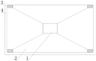
Fig. 1 is a top view of the present invention;
FIG. 2 is a partial top view of the inventive sink;
FIG. 3 is a cross-sectional view of the spout of the present invention;
FIG. 4 is a partial schematic view of the leak groove of the present invention;
fig. 5 is an enlarged view of a portion a in fig. 3 according to the present invention.
In the figure: 1. a high pedestal; 2. a sloping plate; 3. a leak groove; 31. an outer frame; 32. an inner frame; 33. a leakage net; 34. a water collecting frame; 35. a water collecting pipe; 36. a water inlet cavity; 37. a water inlet groove; 38. a water collecting tank; 39. a water outlet; 391. a water outlet groove; 392. a water outlet pipe; 393. a threaded seat; 394. a threaded plug; 395. a drive motor; 396. a motor frame; 4. an outer seat.
Detailed Description
The technical solutions in the embodiments of the present invention will be described clearly and completely with reference to the accompanying drawings in the embodiments of the present invention, and it is obvious that the described embodiments are only some embodiments of the present invention, not all embodiments. Based on the embodiments in the present invention, all other embodiments obtained by a person skilled in the art without creative work belong to the protection scope of the present invention.
Referring to fig. 1-4, the energy-saving and water-saving device for building provided by the present invention comprises a high pedestal 1, an inclined plate 2, a leakage groove 3 and an outer pedestal 4, wherein the inclined plate 2 is disposed on the outer side of the high pedestal 1, the leakage groove 3 is disposed on the end of the inclined plate 2 away from the high pedestal 1, the height of the high pedestal 1 is higher than that of the leakage groove 3, the leakage groove 3 comprises an outer frame 31, an inner frame 32, a leakage net 33, a water collecting frame 34, a water collecting pipe 35, a water inlet chamber 36, a water inlet tank 37, a water collecting tank 38 and a water outlet 39, the leakage net 33 is disposed inside the outer frame 31, the inner frame 32 is disposed on one side of the leakage net 33 away from the outer frame 31, the inner frame 32 is fixedly connected with the outer frame 31, the water collecting frame 34 is disposed below the leakage net 33, the water collecting frame 34 is fixedly mounted on the outer frame 31, the water collecting pipe 35 is fixedly connected with the bottom of the outer frame 31, the water collecting pipe 35 is, the bottom fixed mounting who gathers water pipe 35 gathers on water tank 38, water outlet 39 has been seted up to the bottom of gathering water tank 38, the rainwater flows downwards through the guide of swash plate 2, enter into the inside of inside casing 32, the inside rainwater of inside casing 32 enters into and gathers in water frame 34 after the filtration of leaking net 33, impurity has been had in the rainwater this moment, it guides the rainwater to gather water frame 34, make the rainwater enter into and gather in the inside intake antrum 36 of water pipe 35, the inside rainwater of intake antrum 36 flows downwards, enter into the inside of gathering water tank 38 and store after 37 intake channels.
Referring to fig. 5, the water outlet 39 includes a water outlet groove 391, a water outlet pipe 392, a threaded seat 393, a threaded plug 394, a driving motor 395 and a motor frame 396, the bottom of the water outlet groove 391 is fixedly connected with the water outlet pipe 392, the interior of the water outlet pipe 392 is communicated with the interior of the water collecting tank 38 through the water outlet groove 391, one side of the water outlet pipe 392 is provided with the threaded seat 393, the threaded seat 393 is fixedly installed on the water outlet pipe 392, the threaded plug 394 is arranged in the threaded seat 393, the threaded seat 393 is in threaded connection with the threaded plug 394, the driving motor 395 is arranged on the outer side of the threaded plug 394, the motor frame 396 is arranged on the outer side of the driving motor 395, the top end of the motor frame 396 is fixedly connected with the water collecting tank 38, the motor frame 396 is fixedly connected with the water outlet pipe 392, when a part of domestic water which can be completed by a resident needs rainwater, the driving motor 395 is, the threaded plug 394 leaves the threaded seat 393 gradually, the water outlet pipe 392 is not blocked by the threaded plug 394 and is unblocked up and down, rainwater in the water collecting tank 38 flows downwards through the water outlet pipe 392 and enters a resident home to be used, after the use is finished, the driving motor 395 is started again, the driving motor 395 drives the threaded plug 394 to rotate reversely through the rotating shaft, the threaded plug 394 moves inwards in the threaded seat 393, the threaded plug 394 is enabled to block the water outlet pipe 392, downward water supply is stopped, and rainwater is stored continuously.
The working principle is as follows: rainwater flows downwards under the guidance of the inclined plate 2 and enters the inner frame 32, the rainwater in the inner frame 32 enters the water collecting frame 34 after being filtered by the strainer 33, no impurities exist in the rainwater at the moment, the water collecting frame 34 guides the rainwater, the rainwater enters the water inlet cavity 36 in the water collecting pipe 35, the rainwater in the water inlet cavity 36 flows downwards and enters the water collecting tank 38 through the water inlet groove 37 for storage, when part of domestic water which can be finished by the rainwater is needed, the driving motor 395 is started, the driving motor 395 drives the threaded plug 394 to rotate in the threaded seat 393 through the rotating shaft, the threaded plug 394 gradually leaves the threaded seat 393, the water outlet pipe 392 is not blocked by the threaded plug 394 to flow upwards and downwards, the rainwater in the water collecting tank 38 flows downwards through the water outlet pipe 392 and enters residents for use, and after the use is finished, the driving motor 395 is started again, the driving motor 395 drives the threaded plug 394 to rotate reversely through the rotating shaft, the threaded plug 394 moves inwards in the threaded seat 393, the threaded plug 394 blocks the water outlet pipe 392, downward water supply is stopped, and rainwater is stored continuously.
In summary, the following steps: the utility model discloses energy-conserving water saving fixtures for building, the rainwater flows downwards through the guide of swash plate 2, enter into the inside of inner frame 32, the inside rainwater of inner frame 32 enters into gathering the water frame 34 after the filtration of hourglass net 33, no impurity has been had in the rainwater at this moment, gather water frame 34 and guide the rainwater, make the rainwater enter into gather in the inside intake antrum 36 of water pipe 35, the rainwater in the inside intake antrum 36 flows downwards, enter into the inside of gathering the water tank 38 and store after 37 through the intake antrum, when the resident needs the part domestic water that the rainwater can be accomplished, start driving motor 395, driving motor 395 drives plug 394 through the pivot and rotates in screw thread seat 393, plug 394 leaves screw seat 393 gradually, make outlet pipe 392 no longer block by plug 394 unblocked from top to bottom, the rainwater in gathering the water tank 38 flows downwards through outlet pipe 392, enter into the resident and use in the family, after the rainwater storage device is used, the driving motor 395 is started again, the driving motor 395 drives the threaded plug 394 to rotate reversely through the rotating shaft, the threaded plug 394 moves inwards in the threaded seat 393, the threaded plug 394 blocks the water outlet pipe 392, downward water supply is stopped, rainwater is stored continuously, the rainwater storage device can store and utilize rainwater, partial clean tap water consumption is effectively reduced, and the purpose of saving water is achieved.
Although embodiments of the present invention have been shown and described, it will be appreciated by those skilled in the art that changes, modifications, substitutions and alterations can be made in these embodiments without departing from the principles and spirit of the invention, the scope of which is defined in the appended claims and their equivalents.
Claims (6)
1. The utility model provides an energy-conserving water saving fixtures for building, includes high pedestal (1), swash plate (2), small opening (3) and outer seat (4), its characterized in that: an inclined plate (2) is arranged on the outer side of the high pedestal (1), a leakage groove (3) is formed in one end, far away from the high pedestal (1), of the inclined plate (2), the horizontal height of the high pedestal (1) is higher than that of the leakage groove (3), and an outer seat (4) is arranged on the outer side of the leakage groove (3);
the water leakage groove (3) comprises an outer frame (31), an inner frame (32), a water leakage net (33), a water leakage frame (34), a water leakage pipe (35), a water inlet cavity (36), a water inlet groove (37), a water leakage tank (38) and a water outlet (39), wherein the water leakage net (33) is arranged inside the outer frame (31), the inner frame (32) is arranged on one side, away from the outer frame (31), of the water leakage net (33), the inner frame (32) is fixedly connected with the outer frame (31), the water leakage net (33) is fixedly connected with the inner frame (32), the water leakage frame (34) is arranged below the water leakage net (33), the water leakage frame (34) is fixedly installed on the outer frame (31), the water collection pipe (35) is fixedly connected with the bottom of the outer frame (31), the water inlet cavity (36) is arranged inside the water collection pipe (35), the water inlet groove (37) is arranged at the bottom of the water inlet cavity (36), and the water collection pipe (35) is fixedly installed on the water collection tank (, a water outlet (39) is formed in the bottom of the water collecting tank (38).
2. The energy-saving and water-saving device for buildings according to claim 1, characterized in that: the water outlet (39) comprises a water outlet groove (391), a water outlet pipe (392), a threaded seat (393), a threaded plug (394), a driving motor (395) and a motor frame (396), the bottom of the water outlet groove (391) is fixedly connected with the water outlet pipe (392), the threaded seat (393) is arranged on one side of the water outlet pipe (392), the threaded seat (393) is fixedly installed on the water outlet pipe (392), the threaded plug (394) is arranged inside the threaded seat (393), the driving motor (395) is arranged on the outer side of the threaded plug (394), the motor frame (396) is arranged on the outer side of the driving motor (395), the top end of the motor frame (396) is fixedly connected with the water collecting box (38), and the motor frame (396) is fixedly connected with the water outlet pipe (392).
3. The energy-saving and water-saving device for buildings according to claim 1, characterized in that: the water inlet groove (37) is communicated with the interior of the water collecting tank (38).
4. The energy-saving and water-saving device for buildings according to claim 1, characterized in that: the top end of the water inlet cavity (36) is communicated with the inside of the outer frame (31).
5. The energy-saving and water-saving device for buildings according to claim 2, characterized in that: the threaded seat (393) is in threaded connection with the threaded plug (394).
6. The energy-saving and water-saving device for buildings according to claim 2, characterized in that: the interior of the water outlet pipe (392) is communicated with the interior of the water collecting tank (38) through a water outlet groove (391).
Priority Applications (1)
| Application Number | Priority Date | Filing Date | Title |
|---|---|---|---|
| CN202020928158.6U CN213358770U (en) | 2020-05-27 | 2020-05-27 | Energy-saving and water-saving device for building |
Applications Claiming Priority (1)
| Application Number | Priority Date | Filing Date | Title |
|---|---|---|---|
| CN202020928158.6U CN213358770U (en) | 2020-05-27 | 2020-05-27 | Energy-saving and water-saving device for building |
Publications (1)
| Publication Number | Publication Date |
|---|---|
| CN213358770U true CN213358770U (en) | 2021-06-04 |
Family
ID=76125245
Family Applications (1)
| Application Number | Title | Priority Date | Filing Date |
|---|---|---|---|
| CN202020928158.6U Expired - Fee Related CN213358770U (en) | 2020-05-27 | 2020-05-27 | Energy-saving and water-saving device for building |
Country Status (1)
| Country | Link |
|---|---|
| CN (1) | CN213358770U (en) |
-
2020
- 2020-05-27 CN CN202020928158.6U patent/CN213358770U/en not_active Expired - Fee Related
Similar Documents
| Publication | Publication Date | Title |
|---|---|---|
| CN112323907A (en) | Double-supply double-row circulating device for comprehensive utilization of urban water resources | |
| CN203129266U (en) | Filter type modularized water draining and saving device on same floor for high-rise building | |
| CN201474010U (en) | Relay type building purification water saving device | |
| CN201843184U (en) | Novel water-saving system for household kitchen and bathroom | |
| CN213773566U (en) | Water-saving device for building | |
| CN201047491Y (en) | Domestic sewage clean-up automatic voltage increase recycle device | |
| CN2890189Y (en) | Recovery and utilization device for rain water and domestic wastewater | |
| CN2324192Y (en) | Toilet waste water recovery and utilization apparatus | |
| CN2443049Y (en) | Comprehensive water saver for building toilet | |
| CN202689113U (en) | Household multifunctional water-saving tank | |
| CN216892677U (en) | Domestic wastewater recycling system | |
| CN2536655Y (en) | Comprehensive waste water utilizing apparatus | |
| CN102943509B (en) | Modular same floor drainage water-saving device | |
| CN113718895A (en) | Water-saving device for domestic toilet | |
| CN201071314Y (en) | Integrated domestic water-saving device | |
| CN215594219U (en) | Domestic wastewater collection device | |
| CN2518914Y (en) | Device for recovering domestic sewage from floor drain | |
| CN101372837A (en) | Residential Water Saving System | |
| CN219261238U (en) | Double-hole water-saving hand basin | |
| CN219491172U (en) | Water-saving toilet | |
| CN220125619U (en) | Filter purification device for domestic sewage | |
| CN2890188Y (en) | Single-pipeline sewage recycling device driven by tap water | |
| CN111305313A (en) | Domestic bathroom water conservation system | |
| CN221276727U (en) | Energy-saving environment-friendly mobile house | |
| CN218371904U (en) | House reclaimed water collecting, treating and recycling system |
Legal Events
| Date | Code | Title | Description |
|---|---|---|---|
| GR01 | Patent grant | ||
| GR01 | Patent grant | ||
| CF01 | Termination of patent right due to non-payment of annual fee |
Granted publication date: 20210604 |