Combined resistance box with prevent falling function
Technical Field
The utility model relates to the technical field of resistance, specifically be a combined resistance box with prevent falling function.
Background
The resistance is a physical quantity, and in physics, the resistance represents the magnitude of the current blocking effect of a conductor, the larger the resistance of the conductor, the larger the current blocking effect of the conductor, different conductors generally have different resistances, the resistance is a characteristic of the conductor itself, the resistance will cause the change of electron flow, the smaller the resistance, the larger the electron flow, and vice versa, and the superconductor has no resistance.
The resistance box is the assembly of a plurality of definite value precision resistors, they are installed at same incasement, change its resistance through conversion equipment, current resistance box is mostly all exclusive use, the change volume of resistance is invariable completely, and need great resistance sometimes when the experiment, need less resistance sometimes, it is comparatively difficult to connect the wiring when connecting series connection or parallel circuit and being used for improving or reducing resistance, and current resistance box does not possess and prevents falling the ability, very easy damage that falls.
SUMMERY OF THE UTILITY MODEL
An object of the utility model is to provide a combined resistance box with prevent falling function to propose current resistance box in solving above-mentioned background art and all be the exclusive use mostly, the change volume of resistance is invariable completely, and need great resistance sometimes when the experiment, need less resistance sometimes, it is comparatively difficult to connect the wiring when connecting series connection or parallel circuit and being used for improving or reducing resistance, and current resistance box does not possess prevents falling the ability, the very easy problem of falling the damage.
In order to achieve the above object, the utility model provides a following technical scheme: the utility model provides a combined resistance box with prevent falling function, includes the resistance box, the upper end of resistance box is rotated and is installed adjust knob, the left side fixed mounting of resistance box upper end rear side has first terminal, the right side fixed mounting of resistance box upper end rear side has the second terminal, the fixed right spread groove that is provided with in both sides around the resistance box right-hand member, the fixed left connecting block that is provided with in both sides around the resistance box left end, right spread groove and left connecting block looks adaptation, the fixed right electricity groove that connects that is provided with in middle part of resistance box right-hand member, the fixed left electricity piece that connects that is provided with in middle part of resistance box left end, the electricity groove that connects on the right side connects electricity piece looks adaptation with the left side.
Preferably, the fixed preceding connecting block that is provided with in the left and right sides of resistance box front end, the fixed back spread groove that is provided with in the left and right sides of resistance box rear end, preceding connecting block and back spread groove looks adaptation, the fixed front wiring groove that is provided with in middle part of resistance box front end, the fixed resistance box that is provided with in middle part of resistance box rear end, preceding wiring groove connects electric block looks adaptation with the back.
Preferably, the right end fixed mounting that connects the inside right side of electric tank connects has the right side to connect the electric piece, connect fixedly connected with first connecting wire between electric piece and the second terminal on the right side, the left end fixed mounting of first connecting wire connects the electric piece on the left side, connect fixedly connected with second connecting wire between electric piece and the left side to connect between the electric piece on the left side.
Preferably, the left side fixed mounting who connects the electricity piece rear end after has first back connection piece, first back connection piece and first terminal between fixedly connected with third connecting wire, the right side fixed mounting who connects the electricity piece rear end after has the second back connection piece, second back connection piece and second terminal between fixedly connected with fourth connecting wire, the left side fixed mounting of preceding wiring inslot portion has first preceding connection piece, fixedly connected with fifth connecting wire between first preceding connection piece and the first terminal, preceding wiring inslot portion's right side fixed mounting has the second preceding connection piece, fixedly connected with sixth connecting wire between second preceding connection piece and the second terminal.
Preferably, the top fixed mounting of resistance box inside has the reservation storehouse, reserve the storehouse equidistance and arrange at the inside top of resistance box, it is provided with the determining deviation to reserve between the storehouse fixedly.
Preferably, the fixed weight that is provided with of lower extreme of resistance box, the fixed spring groove that is provided with of lower extreme of weight that increases, the lower extreme movable mounting of weight has vibration damping mount, vibration damping mount's upper end extends to the inside in spring groove, vibration damping mount's upper end is located the fixed limiting plate that is provided with in inside in spring groove, limiting plate and spring groove looks adaptation, the inside fixedly connected with damping spring who is located the spring groove between vibration damping mount's upper end and the lower extreme of the weight that increases, damping spring equidistance is arranged in the inside in spring groove.
Compared with the prior art, the beneficial effects of the utility model are that:
1. according to the combined resistance box with the anti-falling function, the right electricity connecting groove and the left electricity connecting block which are matched are installed and are respectively connected with the second binding post and the first binding post through the first connecting wire and the second connecting wire, so that the resistance box body can be transversely combined into a series circuit, the resistance of the resistance box is increased, meanwhile, the resistance box body can be longitudinally combined into a parallel circuit, and the resistance of the resistance box is reduced;
2. according to the combined resistance box with the anti-falling function, the reserved bin is installed, helium gas can be filled into the reserved bin, so that the weight of the upper end of the combined resistance box is reduced, the gravity center of the resistance box is lowered, and the bottom of the combined resistance box is grounded when the combined resistance box falls freely;
3. this combined resistance box with prevent falling function through the installation increase heavyweight, can further move down the focus of this resistance box, and the bottom lands when further making it freely fall, passes through damping spring installation vibration damping mount in the bottom of this resistance box simultaneously, can receive vibration damping mount's shock attenuation when this resistance box falls to the ground, and then the effectual inside electrical component of resistance box that has protected.
Drawings
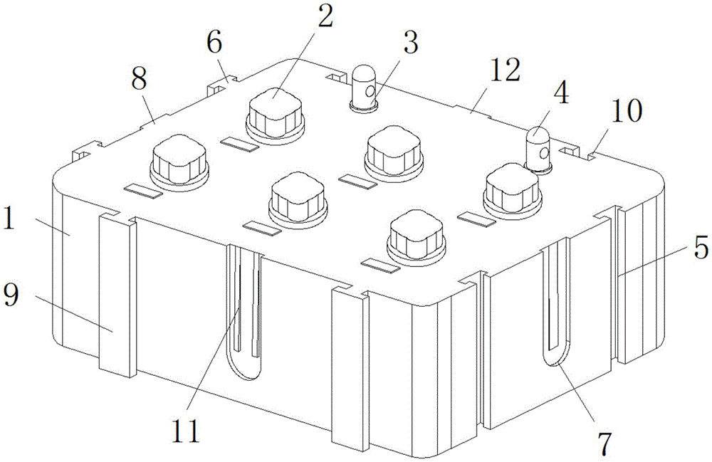
FIG. 1 is a schematic perspective view of the present invention;
FIG. 2 is a schematic cross-sectional structure of the present invention;
FIG. 3 is a schematic longitudinal sectional view of the present invention;
FIG. 4 is a schematic view of the cross-sectional structure of the rear connection block of the present invention;
fig. 5 is a schematic view of the sectional structure of the front wiring groove of the present invention.
In the figure: 1. a resistance box body; 2. adjusting a knob; 3. a first terminal post; 4. a second terminal; 5. a right connecting groove; 6. a left connecting block; 7. the right side is connected with an electric tank; 8. a left power connection block; 9. a front connecting block; 10. a rear connecting groove; 11. a front wiring slot; 12. connecting a rear power block; 13. the right side connects the electric piece; 14. a first connecting line; 15. the left side is connected with the electric piece; 16. a second connecting line; 17. the first rear connecting piece; 18. a third connecting line; 19. the second rear connecting piece; 20. a fourth connecting line; 21. a first front connecting piece; 22. a fifth connecting line; 23. a second front connecting piece; 24. a sixth connecting line; 25. reserving a bin; 26. a weight increasing block; 27. a spring slot; 28. a damping mount; 29. a limiting plate; 30. a shock absorbing spring.
Detailed Description
The technical solutions in the embodiments of the present invention will be described clearly and completely with reference to the accompanying drawings in the embodiments of the present invention, and it is obvious that the described embodiments are only some embodiments of the present invention, not all embodiments. Based on the embodiments in the present invention, all other embodiments obtained by a person skilled in the art without creative work belong to the protection scope of the present invention.
Referring to fig. 1-5, the present invention provides a technical solution: the utility model provides a combined resistance box with prevent falling function, including resistance box 1, resistance box 1's upper end is rotatory installs adjust knob 2, the left side fixed mounting of 1 upper end rear sides of resistance box has first terminal 3, the right side fixed mounting of 1 upper end rear sides of resistance box has second terminal 4, both sides are fixed around the 1 right-hand member of resistance box are provided with right spread groove 5, both sides are fixed around the 1 left end of resistance box are provided with left connecting block 6, right spread groove 5 and 6 looks adaptations of left connecting block, the fixed right electricity groove 7 that connects that is provided with in middle part of 1 right-hand member of resistance box, the fixed left electricity piece 8 that connects that is provided with in middle part of 1 left end of resistance box, right electricity groove 7 and the electricity 8 looks adaptations of left.
Further, fixed preceding connecting block 9 that is provided with in the left and right sides of 1 front end of resistance box, the fixed back spread groove 10 that is provided with in the left and right sides of 1 rear end of resistance box, preceding connecting block 9 and back spread groove 10 looks adaptation, the fixed preceding connecting groove 11 that is provided with in middle part of 1 front end of resistance box, the fixed resistance box 1 that is provided with in middle part of 1 rear end of resistance box, preceding connecting groove 11 connects electric block 12 looks adaptation with the back, right spread groove 5 and left connecting block 6 through the installation looks adaptation, can realize horizontal high-speed joint installation between the resistance box 1, the preceding connecting block 9 and the back spread groove 10 of installation simultaneously, can realize fore-and-aft high-speed joint installation between the resistance box 1, and the stable in structure of installation is difficult for separating, improve the wiring stability.
Further, the right end fixed mounting who connects the inside of electric tank 7 on the right side connects electric piece 13 on the right side, connect the first connecting wire 14 of fixedly connected with between electric piece 13 and the second terminal 4 on the right side, the left end fixed mounting of first connecting wire 14 connects electric piece 15 on the left side, connect electric piece 15 and connect fixedly connected with second connecting wire 16 between electric piece 15 on the left side, connect electric tank 7 and the left side through the right side of installation looks adaptation and connect electric piece 8, and make it connect second terminal 4 and first terminal 3 respectively through first connecting wire 14 and second connecting wire 16, can make the horizontal series circuit that makes up of resistance box 1, and then increase the resistance of this resistance box.
Further, a first rear electric connecting piece 17 is fixedly installed on the left side of the rear end of the rear electric connecting block 12, a third connecting wire 18 is fixedly connected between the first rear electric connecting piece 17 and the first binding post 3, a second rear electric connecting piece 19 is fixedly installed on the right side of the rear end of the rear electric connecting block 12, a fourth connecting wire 20 is fixedly connected between the second rear electric connecting piece 19 and the second binding post 4, a first front electric connecting piece 21 is fixedly installed on the left side inside the front wiring groove 11, a fifth connecting wire 22 is fixedly connected between the first front electric connecting piece 21 and the first binding post 3, a second front electric connecting piece 23 is fixedly installed on the right side inside the front wiring groove 11, a sixth connecting wire 24 is fixedly connected between the second front electric connecting piece 23 and the second binding post 4, the third connecting wire 18 is connected between the first rear electric connecting piece 17 and the first binding post 3, the fourth connecting wire 20 is connected between the second rear electric connecting piece 19 and the second binding post 4 by installing the front electric connecting piece 21 and the rear electric connecting piece 12 which are matched with, A fifth connecting wire 22 is connected between the first front electric connecting piece 21 and the first binding post 3, and a sixth connecting wire 24 is connected between the second front electric connecting piece 23 and the second binding post 4, so that the resistor box body 1 can be longitudinally combined into a parallel circuit, and the resistance of the resistor box is further reduced.
Furthermore, the reserved bins 25 are fixedly installed at the top inside the resistor box body 1, the reserved bins 25 are arranged at the top inside the resistor box body 1 at equal intervals, a certain distance is fixedly arranged between the reserved bins 25, helium can be filled into the reserved bins 25 through installation of the reserved bins 25, the weight of the upper ends of the reserved bins is reduced, the center of gravity of the resistor box is lowered, and the bottom of the resistor box is grounded when the resistor box falls freely.
Furthermore, the lower end of the resistance box body 1 is fixedly provided with a weight increasing block 26, the lower end of the weight increasing block 26 is fixedly provided with a spring groove 27, the lower end of the weight increasing block 26 is movably provided with a damping base 28, the upper end of the damping base 28 extends into the spring groove 27, the upper end of the damping base 28 is positioned in the spring groove 27 and is fixedly provided with a limiting plate 29, the limiting plate 29 is matched with the spring groove 27, a damping spring 30 is fixedly connected between the upper end of the damping base 28 and the lower end of the weight increasing block 26 and positioned in the spring groove 27, the damping springs 30 are distributed in the spring groove 27 at equal intervals, the gravity center of the resistance box can be further moved downwards through the installation of the weight increasing block 26, the bottom of the resistance box is further enabled to be landed when the resistance box freely falls, meanwhile, the damping base 28 is installed at the bottom of the resistance box through the damping, thereby effectively protecting the electric elements in the resistance box.
The working principle is as follows: the right connecting groove 5 and the left connecting groove 6 which are matched with each other are installed, so that transverse quick connection and installation between the resistance box bodies 1 can be realized, the front connecting block 9 and the rear connecting groove 10 which are installed at the same time can realize longitudinal quick connection and installation between the resistance box bodies 1, the installed structure is stable and not easy to separate, the wiring stability between the resistance box bodies is improved, the right connecting groove 7 and the left connecting block 8 which are matched with each other are installed, the right connecting groove 7 and the left connecting block 8 are respectively connected with the second wiring terminal 4 and the first wiring terminal 3 through the first connecting wire 14 and the second connecting wire 16, the resistance of the resistance box bodies 1 can be transversely combined into a series circuit, the resistance of the resistance box is increased, the third connecting wire 18 is connected between the first rear electric connecting piece 17 and the first wiring terminal 3, and the fourth connecting wire 20 is connected between the second rear electric connecting piece 19 and the second wiring terminal 4 through the front connecting groove 11, The fifth connecting wire 22 is connected between the first front electric connecting piece 21 and the first binding post 3, the sixth connecting wire 24 is connected between the second front electric connecting piece 23 and the second binding post 4, so that the resistor box body 1 can be longitudinally combined into a parallel circuit, the resistance of the resistor box is further reduced, helium can be filled into the reserved bin 25 by installing the reserved bin 25, the weight of the upper end of the helium is reduced, the gravity center of the resistor box is lowered, the bottom of the resistor box is enabled to be landed when the gravity center of the resistor box freely falls, the gravity center of the resistor box can be further lowered by installing the weight increasing block 26, the bottom of the resistor box is further enabled to be landed when the gravity center of the resistor box freely falls, meanwhile, the damping base 28 is installed at the bottom of the resistor box through the damping spring 30, the damping base 28 can absorb the shock when the resistor box falls to the.
It should be finally noted that the above only serves to illustrate the technical solution of the present invention, and not to limit the scope of the present invention, and that simple modifications or equivalent replacements performed by those skilled in the art to the technical solution of the present invention do not depart from the spirit and scope of the technical solution of the present invention.